Development of a real-time magnetic island reconstruction system based on PCIe platform for HL-2A tokamak
2021-08-05XiaopengLI李枭鹏ChaoCHEN陈超WeiweiFAN范伟伟RenjieZHU朱仁杰SichengHUANG黄思诚XinchengWEN温昕澄ZongwuHE何宗武QingweiYANG杨青巍andZejieYIN阴泽杰
Xiaopeng LI (李枭鹏), Chao CHEN (陈超), Weiwei FAN (范伟伟),Renjie ZHU(朱仁杰),Sicheng HUANG(黄思诚),Xincheng WEN(温昕澄),Zongwu HE (何宗武), Qingwei YANG (杨青巍) and Zejie YIN (阴泽杰)
1 State Key Laboratory of Particle Detection and Electronics, University of Science and Technology of China, Hefei 230026, People’s Republic of China
2 Department of Modern Physics,University of Science and Technology of China,Hefei 230026,People’s Republic of China
3 Southwestern Institute of Physics, Chengdu 610041, People’s Republic of China
Abstract A real-time magnetic island reconstruction(MIR)system based on PCI express platform for HL-2A tokamak is introduced.The front-end analog circuit and high performance analog-to-digital converters complete high-precision synchronous sampling of 18 channel Mirnov signals,and the application of PCIe platform and direct memory access technology enables high speed data transmission between graphics processing unit and field programmable gate array (FPGA).FPGA, as a mainstream high speed parallelizable computing tool, was used to implement the MIR algorithm,while a parameter table is established in an external double data rate SDRAM to improve the computational efficiency.The software of the MIR system is developed with Compute Unified Device Architecture 8.0 in Centos 6 system, which mainly realizes driver development, data transmission, network communication, parameter calculation and system control.This system has been tested in HL-2A plasma discharge experiment, and the reconstructed magnetic island structure can achieve a spatial resolution of 1.02 cm while the time resolution can reach 2 ms.
Keywords: magnetic island reconstruction, real-time, FPGA, PCIe, GPU
1.Introduction
Magnetohydrodynamic (MHD) instability, especially the tearing mode,is one of the most important issues on tokamak plasma research [1].It can lead to the degradation of plasma confinement and even discharge disruption.When MHD instability exists in the plasma,the topological structure of the magnetic field will be changed, and the magnetic field lines will break and reconnect at the rational surface to form magnetic islands [2].It is very important to observe the magnetic island structure and analyze its evolution process for understanding and controlling MHD instability.At present,the common methods to identify the magnetic island structure include soft x-ray tomography and electron cyclotron radiation [3–6].In the HL-2A tokamak device, the MHD instabilities, especially the tearing modes,are investigated by Mirnov probes,and the magnetic island reconstruction(MIR)method on the basis of Mirnov signals and the equilibrium fit(EFIT) code has been developed gradually in recent years[7–9].In this method, the mode number of the tearing mode can be firstly obtained by analyzing the Mirnov signals, and the real perturbation field is simulated by the magnetic field induced by the perturbation current distributed on the rational surface.Then, the simulated perturbation field is fitted with the real value calculated by Mirnov signals to obtain the distribution of perturbation flux.Finally, the magnetic island structure can be observed by superimposing the artificial equilibrium flux and the perturbation flux in the corresponding position.
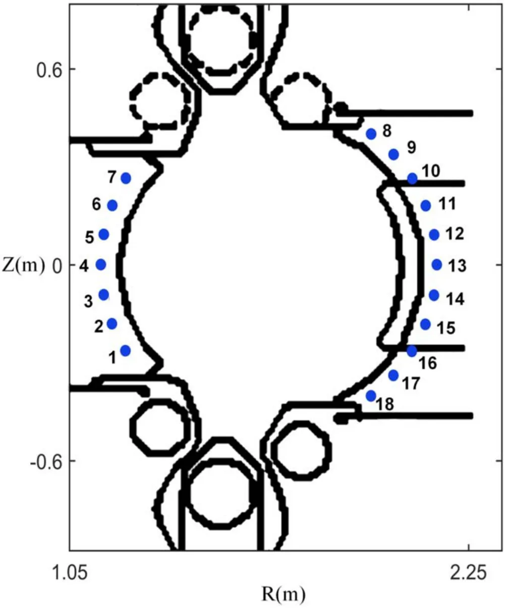
Figure 1.The locations of 18 Mirnov probes on HL-2A.
The method above was applied to analyze the experimental data in previous plasma discharge experiments,indicating its validity [10].In the next phase of plasma discharge experiment, the HL-2A plasma diagnosis system requires real-time position of magnetic island to suppress the tearing mode[11–14].For this,we developed a real-time MIR system.The front-end analog circuit and high performance ADCs complete the high-precision signal acquisition of Mirnov probes.With the advantage of parallel pipelined programming in FPGA, the MIR algorithm can be implemented in real-time, while a parameter table is established in an external DDR to further improve the calculation efficiency.Furthermore, the application of PCIe platform and DMA technology promotes the high speed data transmission between GPU and FPGA.The software of the MIR system is developed in Centos 6 system with CUDA 8.0 computing platform, which mainly realizes driver development, data transmission, network communication, parameter calculation and system control.Trials of the system have been successfully carried out on HL-2A, and the results indicate that time resolution of MIR system can reach 2 ms and spatial resolution can reach 1.02 cm.
The article is organized as follows.Section 2 introduces the algorithm of the MIR.Section 3 describes the detailed design of the MIR system, including the hardware structure,FPGA program, and software.The experimental results and system performance are presented in the section 4.The conclusion is expressed in section 5.
2.Principle of MIR
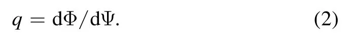
The MIR method based on Mirnov probes and EFIT code is described in detail in [15, 16].The distribution of poloidal equilibrium flux can be calculated by EFIT code through solving the Grad–Shafranov equation [17, 18].In fact,EFIT code has been widely applied to reconstruct the MHD equilibrium in many tokamak devices [19, 20].The safety factorq, the coordinates of magnetic axis and the resonant surface can also be obtained by EFIT results.Then, the artificial equilibrium fluxΨhcan be calculated according to formula (1):
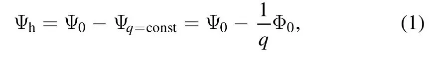
whereqis the safety factor at rational surface.Ψ0and Φ0represent poloidal equilibrium flux and toroidal equilibrium flux respectively.Ψ=qconst is the zero shear field.By subtractingΨq=constfromΨ0,Ψhcan be obtained.The distribution ofΨ0and safety factorqcan be acquired directly from EFIT data, while Φ0can be calculated based on the formula (2)
The perturbation field outside the plasma can be measured by Mirnov probes.Figure 1 depicts a set of Mirnov probes equipped on the HL-2A tokamak, consisting of 18 coils arranged along the poloidal direction with an angle of 10.5° between adjacent probes.In order to calculate the perturbation field, the perturbation current model is applied [21].The perturbation field is simulated by the magnetic field induced by the perturbation current filaments distributed on the resonant magnetic surface.The location of simulated current filaments can be determined by the EFIT data.Considering that the perturbation current is linear circular current flowing along the rational surface,when calculating the two-dimensional structure of the magnetic island in the polar section, the expression of current filaments can be recorded as formula (3):
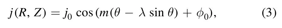
where θ is the angle from the current filament to the horizontal line, andmrepresents the value of poloidal mode.Through the analysis of Mirnov signals, the type of tearing mode can be obtained, and thenmcan be determined.At this stage, the algorithm is mainly used to analyzem/n=2/1 mode.j0,λandφ0are three unknown variables.The magnetic field induced by current filaments is regarded as the simulated value of the perturbation field at the positions of 18 Mirnov probes, and the three unknown variables can be obtained by the least square method, as shown in formula (4):

Figure 2.The overall structure of the MIR system.
whereBiis the component of the simulated perturbation field in the detection direction of the No.iMirnov probe,Bi0is the real perturbation field measured by No.iMirnov probe, and the three parameters are determined by minimizingδ.2 Then, the distribution of the perturbation flux is calculated according to current filament values.Finally,the artificial helical fluxΨ can be obtained by superimposing the artificial equilibrium fluxΨhand the perturbation flux Ψperas formula (5):
and the structure and location of magnetic island can be observed by displaying the contour of the distribution of Ψ.
3.Design of the MIR system
According to the principle of the above MIR algorithm, the electronic system to be designed for real-time reconstruction of magnetic island structure needs to achieve the following functions:
(1) High-precision synchronous acquisition of 18 Mirnov probes.
(2) High speed transmission of EFIT data during plasma discharge experiments.
(3) Real-time implementation of MIR algorithm with high speed computing capability.
(4) Real-time feedback of calculation results to control system of tearing mode.
As a mainstream high speed parallelizable computing tool, FPGA has been widely used in the high speed implementation of complex algorithms.We chose FPGA to realize the real-time programming of MIR algorithm.Considering that the EFIT code is running on a high performance workstation DELL T630, and the poloidal equilibrium flux is calculated in parallel by a supercomputing graphics card NVIDIA Tesla K20 [22].In order to facilitate the data transmission between FPGA and GPU, we designed the electronic system based on PCIe platform.
Figure 2 illustrates the overall architecture of the MIR system.It mainly consists of two parts, the analog conditioning module MIR-1, the data processing module MIR-2.The MIR-1 is designed as a standard nuclear instrumentation module crate.18 single-ended analog input channels receive the Mirnov signals through the BNC connectors on the front panel.The detected signals are preliminarily adjusted by the front-end analog circuit in MIR-1.Then, the processed signals are output to MIR-2 through the SCSI-100 connector.Specifically, in order to minimize the external electromagnetic interference and the crosstalk between multi channels,a shielded twisted pair is used for the analog signal transmission between the two boards.The MIR-2 is designed as a PCIe device installed in the chassis of DELL T630,and it receives Mirnov signals and EFIT data,and realizes real-time MIR algorithm.As shown in figure 2, the data transmission from graphics card to FPGA is divided into two steps.The first step is from graphics card to host memory, while the second step is from host memory to FPGA.Both steps are transmitted in DMA mode.The software is developed based on CUDA 8.0 in Centos 6 system, which accomplishes the driver development, data transmission, network communication, parameter calculation and system control.The calculation results are transmitted to the host memory through the PCIe interface, providing a real-time feedback for the control system of tearing mode in HL-2A [23].
3.1.Hardware structure
Since the Mirnov signal of each channel needs necessary analog preprocessing before analog-to-digital conversion,it is unrealistic to integrate all the circuits and chips on a single PCIe device.Therefore, an additional analog conditioning module MIR-1 is designed to complete the analog conditioning of all detected signals before analog-to-digital conversion.Figure 3 describes the structure of MIR-1, and each Mirnov signal needs to undergo three stages of signal conditioning.The first stage is an attenuation resistance network, and it is used to adjust the amplitude of the detected signals and expand the dynamic input range.The ADC we selected—ADS1278 requires that the input signal must be differential signal.Therefore, in the next stage, the fully differential amplifier AD8139 is applied to convert the singleended input signal into differential signal.In the final stage,an anti-aliasing filter is designed to prevent the interference of high frequency noise.The processed analog signal is output through the SCSI-100 connector on the back panel.

Figure 3.The hardware architecture of MIR-1.
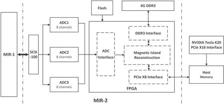
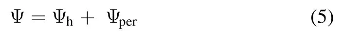
Figure 4.The hardware architecture of MIR-2.
Figure 4 depicts the structure of the data processing module MIR-2.We select the high performance ADC chip TI ADS1278 to complete signal sampling.It is a fully differential eight-channel ∑–Δ ADC with 24 bit resolution and supports up to 144 KSPS sampling rate.In addition, a high performance FPGA Xilinx Virtex-6 xc6vlx240t is selected to realize data communication and real-time calculation.A flash chip xcf128xftg64c is used to complete the configuration of the FPGA program.In addition,an additional 4G SAMSUNG DDR3 is used for high speed data storage.Furthermore, the PCIe interface is designed for data transmission among FPGA, host memory, and GPU.
3.2.FPGA program
Figure 5 describes the data processing procedure in FPGA.The Mirnov signals are sampled by ADCs, and the serial peripheral interface logic is designed in FPGA to receive the sampled data of each channel in parallel.The maximum sampling rate supported by ADC is 144 KSPS, and by choosing the working mode of ADC,the actual sampling rate is set to 100 KSPS.Considering that the data sampled by ADC is induced voltage value, digital integration and drift compensation are realized to calculate the magnetic field value.In fact, the large scale dominant mode is commonly figured by continuous high amplitude of the Mirnov measurements.When the measured value continuously exceeds the threshold value set in the FPGA, a fast Fourier transform filter (FFT) is programmed for each channel to extract the main mode of the perturbation field from other harmonics and noise.Digital integration, drift compensation, and FFT filter filtering are designed in parallel in FPGA, which can greatly reduce the calculation time.Through the process, the magnetic field values measured by Mirnov probes in each channel are obtained.
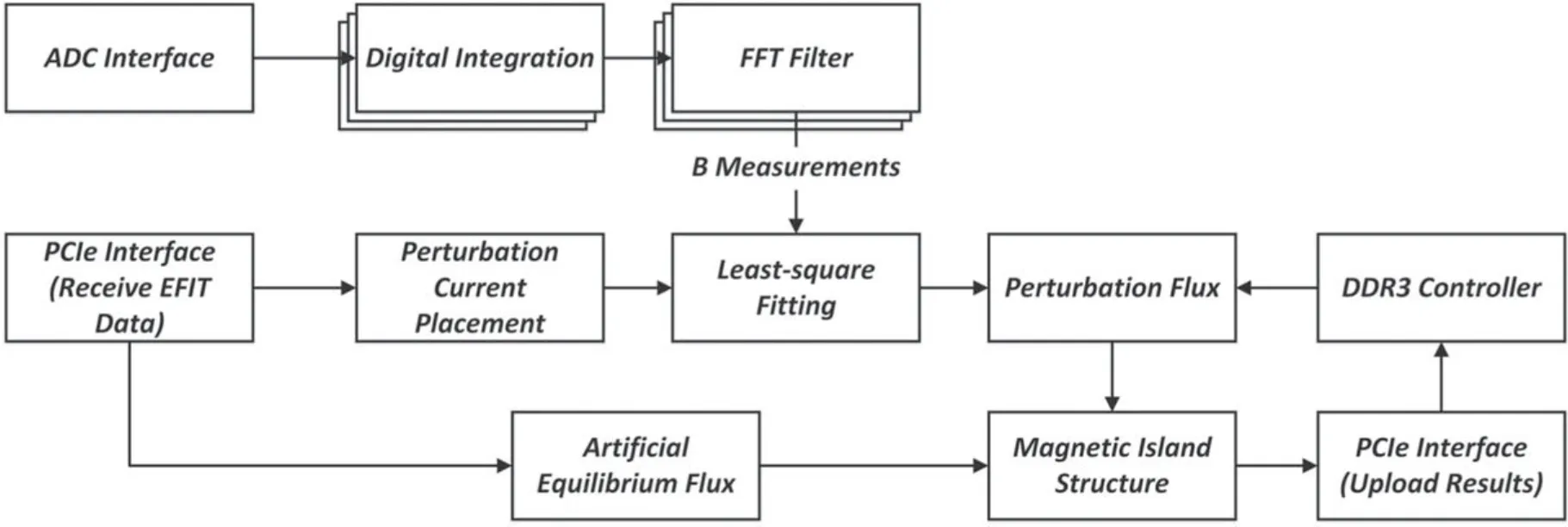
Figure 5.The data processing procedure in the FPGA.
Utilizing the GTX transceivers in FPGA,the DMA readwrite program was designed as a ‘DMA controller’ for high speed data transmission.In the process of calculating the magnetic field measured by Mirnov probes, EFIT data is transferred to FPGA in DMA mode through the PCIe interface.In EFIT data, the grid matrix is applied to represent the flux distribution of the poloidal section.In order to improve the spatial resolution, the grid matrix is developed from 33×33 to 129×129 which covers the poloidal section of 1.75 m×1.3 m in HL-2A tokamak [24–26].Besides the poloidal equilibrium flux matrix,the safety factorqsequence,the grid coordinates, the position of magnetic axis, the experimental time of plasma discharge and other parameters are also extracted from EFIT data.
Then, in order to calculate the perturbation flux, 20 current filaments are equiangular distributed on the rational surface on the basis of perturbation current model described in section 2.The expression of each current filament is shown in formula (3).After the parameters are determined by the least square multiplication, the perturbation flux can be obtained by formula (6)
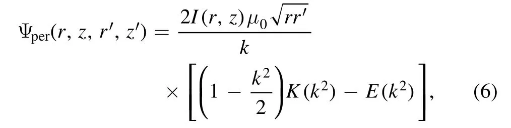
where
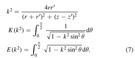
In formula (6),Ψper(r,z,r′ ,z′) represents the perturbation flux at grid point( ′ ′r z, )which is induced by perturbation current filament at grid pointr z, .( )KandEare complete elliptic integrals,as shown in formula(7).At each grid point,the perturbation flux can be obtained by superimposing the induced flux generated by 20 current filaments.However, if the perturbation flux is calculated directly according to formula (6), it will need 20×129×129 cycles, and each cycle includes complex operations such as integral, sqrt and division,which requires a long data processing time in FPGA and the results cannot be obtained in real-time.
In fact, equation (6) can be expressed as the product of perturbation currentIand parameterT:
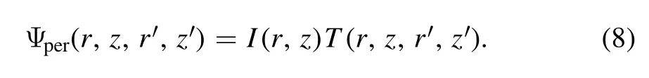
In formula (8), the parameterTis only related to the current filament coordinate and the grid point position, and can be calculated in advance by host computer and sent to FPGA to form a parameter table.When the perturbation flux is to be calculated, the parameterTcan be read from the parameter table according to the current filament position.Utilizing the parameter table, the complex computations including sqrt,division, integral, logarithm are avoided in FPGA, which greatly improves the calculation efficiency of perturbation flux distribution.The space needed to store the parameter table is more than 2 GB, which far beyond the storage capacity of the FPGA.Therefore, an additional 4G SAMSUNG DDR3 is used for high speed storage for the parameter table.The DDR has the ability of high speed data throughput,and its read-write bandwidth can reach 6.4 GB s−1.
On the other hand, the artificial equilibrium flux is obtained by EFIT data according to formula (1).Then, the final magnetic island structure can be observed by superimposing the artificial equilibrium flux and the perturbation flux.Finally, the results are uploaded to the host memory by the PCIe X8 interface to provide a basis for the analysis and control of tearing mode.
3.3.Software
The software is programed in Centos 6 system with CUDA 8.0—a general parallel computing platform developed by NVIDIA.It can be divided into three layers: driver layer, transport layer and user layer.The driver layer includes the PCIe driver of FPGA and the graphics card.The transport layer completes the data transmission between the two devices.Initialization needs to be performed first.Then,a continuous address space is allocated respectively in device memory and host memory.When the DMA operation starts, the trigger signal activates the DMA controller, and the direct data transmission can be operated between the device and host memory without the intervention ofCPU.In addition, the other necessary functions including parameter calculation, network communication, and system control are realized in the user layer.The MIR system runs together with HL-2A plasma diagnosis system on the workstation located in the high performance computing center,and it is expected to be remotely monitored by HL-2A master control system.Therefore,the ethernet communication interface based on user datagram protocol is designed for remote communication between the diagnosis system and the control system.

Table 1.Bandwidth test between devices and host memory.
The software is compiled by Intel C++ compiler.Compared with ordinary compilers, Intel compiler can provide professional program optimization for Intel Architecture to improve software operating efficiency.The compilation process is simplified by setting appropriate compiler options to lower the compilation difficulty.The compiled software runs as a Linux thread on the workstation DELL T630,which is equipped with a 12-core high performance CPU Intel Xeon E5-2695.Notably,in order to further improve the running speed, a dedicated CPU core is allocated as the carrier of software thread to avoid the occupation of system time slice by multiple threads.
4.Performance of the MIR system
Trials of the system have been successfully carried out on HL-2A.HL-2A is the first tokamak device with advanced divertor configuration and non-circular cross section in China.The major radius of HL-2A tokamak device is 1.65 m,while the minor radius is 0.4 m, and the intensity of the central magnetic field can reach 2.8 T [27].In order to correct the drift of Mirnov signals, the baseline test was carried out which lasts for 2.5 s before the discharge experiment starts.During the plasma discharge experiment, the MIR system samples the Mirnov signals while receiving the EFIT data through the PCIe interface.The results calculated by FPGA are uploaded to the host computer.
4.1.Test for the time resolution of the MIR system
The operation period of MIR system is an important parameter,which is recorded as the time resolution of the MIR.In order to obtain the position and structure of the magnetic island in real-time,and realize the real-time suppression of the tearing mode, the control system of tearing mode requires the time resolution of the MIR system to reach 3 ms.In fact,the operation period includes the time for data processing in FPGA and time for data transmission in software.The data processing time is calculated by counting the consumed clock cycle in FPGA, and the consumed time for data transmission is evaluated by testing the bandwidth.Table 1 records the results of bandwidth test for MIR system.It can be seen from table 1 that the transmission speed of GPU〈—〉host memory, FPGA〈—〉host memory are above 45.9 Gbit s−1and 14.7 Gbit s−1respectively.Considering that the EFIT data is less than 300 kB, and the amount of calculation results is less than 200 kB, the consumed time for data transmission is less than 0.6 ms.Through parallel pipelined design of FPGA program, the calculation time is less than 1.2 ms.Finally, the operation period of MIR system is indicated to be less than 2.0 ms.

Figure 6.The sampled data of No.4 and No.13 Mirnov probes in shot 36355.
4.2.Reconstruction results
Figure 6 shows the sampled data of No.4 and No.13 Mirnov probes in shot 36355.The No.4 and No.13 probes are located in the middle plane of the strong field side and the weak field side respectively.The signal phase of No.4 Mirnov probe is approximately the same as that of No.13 Mirnov probe neart=600 ms, which is the typical characteristic of tearing mode (m/n=2/1).Figure 7 shows the difference between the real magnetic field measured by 18 Mirnov probes and the simulated results att=600 ms.The simulation results are approximately equal to the measured results,which indicates the reliability of the calculation results.Figure 8 shows the artificial equilibrium flux distributed in the poloidal section obtained by EFIT data, and the locations of the rational surface (q=2) and current filaments are also indicated in figure 8.
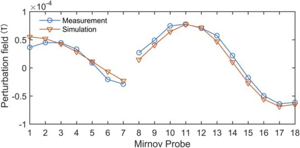
Figure 7.The comparison between the real magnetic field and the simulated magnetic field at t=600 ms in shot 36355.
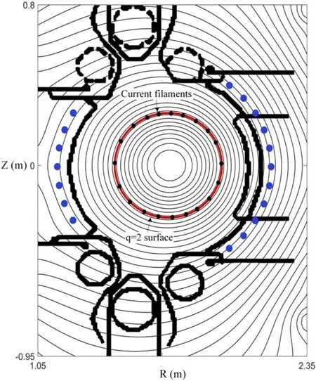
Figure 8.The artificial equilibrium flux at t=600 ms in shot 36355.
The magnetic island structure reconstructed by MIR system att=600 ms is shown in figure 9.From the comparison between figures 8 and 9,it can be seen that the topological structure of the magnetic field is changed due to the MHD instabilities, and the magnetic field lines are broken and reconnected at the rational surface, forming two magnetic islands, which is a typical phenomenon caused by tearing mode(m/n=2/1).By drawing the contour of the flux distribution,we can see that the width of the magnetic island on the left side is about 6.2 cm and that on the right side is 6.0 cm.The O and X points correspond to the maximum and minimum values of the perturbation flux respectively, which are also shown in figure 9.The spatial resolution depends on the grid density,which directly affects the accuracy of calculation results, and further affects the control accuracy of tearing mode.For 129×129 grid density, the spatial resolution can reach 1.02 cm.The calculation results,especially the position of O point and X point, are fed back to the control system of tearing mode in real-time, providing an important basis for the ECRH system to suppress the tearing mode.
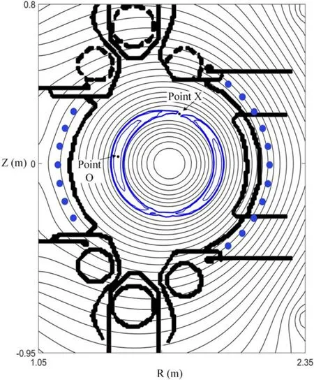
Figure 9.The magnetic islands reconstructed by the MIR system att=600 ms in shot 36355.
5.Conclusion
For the purpose of studying the MHD instability and controlling the tearing mode in real-time,a real-time MIR system based on the PCIe platform was developed.The hardware structure of the system consists of an analog conditioning module MIR-1 and a data processing module module MIR-2.The front-end analog circuit and high performance ADCs complete the data acquisition of Mirnov probes, and the application of PCIe platform and DMA technology completes the high speed data transmission between FPGA and GPU.The current filament mode is applied to calculate perturbation flux, while the artificial equilibrium flux can be obtained by the results calculated by the EFIT code.Parallel pipelining program in FPGA implements real-time MIR algorithm,and a parameter table is established in a DDR3 to improve the computational speed of perturbation flux.The software is developed in Centos 6 system with CUDA 8.0 platform,which aims to complete the driver development, data transmission, network communication, parameter calculation and system control.The MIR system runs as a Linux thread on a separate CPU core without the interference from other threads,which further improves the efficiency of the program.
Trials of the system have been successfully carried out on HL-2A.In DMA mode, the transmission bandwidths of GPU〈—〉host memory, FPGA〈—〉host memory are up to 50.46 Gbit s−1and 15.28 Gbit s−1respectively.The time resolution of MIR is indicated to be less than 2 ms.Them/n=2/1 tearing mode has been successfully observed on the HL-2A tokamak, and the X and O points of the magnetic island can be obtained.In the follow-up research,we will optimize the MIR algorithm and try to analyze other types of tearing modes.In conclusion, this MIR system provides an important basis for the control of tearing mode in plasma discharge experiments on HL-2A.
Acknowledgments
This work is supported by National Natural Science Foundation of China (No.11575184).
杂志排行

Plasma Science and Technology的其它文章
- Two-point model analysis of SOL plasma in EAST
- Line identification of boron and nitrogen emissions in extreme- and vacuumultraviolet wavelength ranges in the impurity powder dropping experiments of the Large Helical Device and its application to spectroscopic diagnostics
- Landau damping of twisted waves in Cairns distribution with anisotropic temperature
- Effects of magnetic field on electron power absorption in helicon fluid simulation
- Dependence of plasma structure and propagation on microwave amplitude and frequency during breakdown of atmospheric pressure air
- Machine learning application to predict the electron temperature on the J-TEXT tokamak