Microwave-assisted pre-ionization experiments on GLAST-III
2021-08-05RiazKHANSehrishSHAKIRAhmadALIMuhammadKhawarAYUBMoazzamNAZIRZiaURREHMANAbdulQAYYUMMuhammadAtharNAVEEDSarfrazAHMADZahoorAHMADRafaqatALIandShahidHUSSAIN
Riaz KHAN,Sehrish SHAKIR,Ahmad ALI ,Muhammad Khawar AYUB,Moazzam NAZIR, Zia UR-REHMAN, Abdul QAYYUM,Muhammad Athar NAVEED, Sarfraz AHMAD, Zahoor AHMAD,Rafaqat ALI and Shahid HUSSAIN
1 Pakistan Tokamak Plasma Research Institute, P.O.Nilore, Islamabad 44000, Pakistan
2 Theoretical Physics Division, PINSTECH, P.O.Nilore, Islamabad 44000, Pakistan
Abstract GLAss Spherical Tokamak (GLAST-III) is a spherical tokamak with an insulating vacuum vessel that has a unique single-passage capability for incident microwaves.In this work,electron cyclotron resonance heating (ECRH)-assisted plasma pre-ionization in GLAST-III is explored for three radio-frequency(RF)polarizations(the O-,X-,and M-modes)at different toroidal-field(TF)strengths and filled gas pressures.The optimum hydrogen pressure is identified for efficient plasma pre-ionization.A comparison of the plasma pre-ionizations initiated by the O-, X-, and M-modes shows prominent differences in the breakdown time,location,and wave absorption.In the case of O-mode polarization, microwave absorption occurs for a relatively shorter duration,resulting in a bell-shaped electron-temperature Te( ) temporal profile.Microwave absorption is dominant in the case of the X-mode, leading to a broader Te temporal profile.The M-mode discharge contains features of both the X- and O-modes.Efficient plasma pre-ionization is achieved in the X-mode polarization for the intermediate TF strengths (with a central toroidal magnetic field B0=0.075T).Traces of the electron-number density show a similar tendency,as r evealed by Te.These results suggest that the X-mode is the best candidate for efficient plasma pre-ionization at low filled gas pressures ( ~10−2Pa) in small tokamaks.
Keywords: GLAST-III, microwave, ECRH, pre-ionization, polarization
1.Introduction
Electron cyclotron resonance heating (ECRH)is an attractive method for auxiliary plasma heating as well as current profile control in magnetically confined fusion plasmas because of its unique properties, such as its quasi-optical propagation,localized absorption, and direct electron heating [1–4].Microwave propagation,absorption,and the impact of higher harmonics are some of the key aspects in ECRH-assisted plasmas [5].Recently, ECRH-assisted plasma start-up has been proposed for several tokamaks,such as KSTAR[6],JT-60SA [7], and ITER [8].Furthermore, it has been found that in JT-60U [9], DIII-D [10, 11], T-10 [12], and Tore Supra[13] experiments, ECRH plays an important role in reducing flux consumption.Numerous analytical studies [14, 15] have been devoted to the investigation of loop-voltage reduction using ECRH.
Microwaves can be launched into a tokamak with different polarizations, leading to different microwave modes.These microwave modes can be distinguished according to the direction of wave polarization with respect to the toroidal magnetic field(BT) [16, 17].The ordinary mode (O-mode)consists of wave propagation with an electric-field vector(Emw)parallel toBT,while the extraordinary mode(X-mode)consists of wave propagation withEmwperpendicular toBT.The mixed mode (M-mode) refers to the cross-polarization[18] which is formed by injecting microwaves into the chamber in such a way thatEmwmakes an angle of 45 degrees withBT.Several ECRH-assisted plasma start-up studies have been performed using the X-mode and the O-mode with fundamental and higher harmonics [19, 20].In the KSTAR tokamak [21], ECRH-assisted plasma breakdown has been found to be delayed by second-harmonic X-mode heating,while ECRH breakdown occurs immediately with the first harmonic O-mode.A comparison of microwave-assisted plasma pre-ionization with the X- and O-mode polarizations was discussed in detail for the START tokamak [22].Therefore, better understanding of the wave-absorption mechanism is essential in investigating ECRH-assisted plasma start-up with different microwave polarizations.
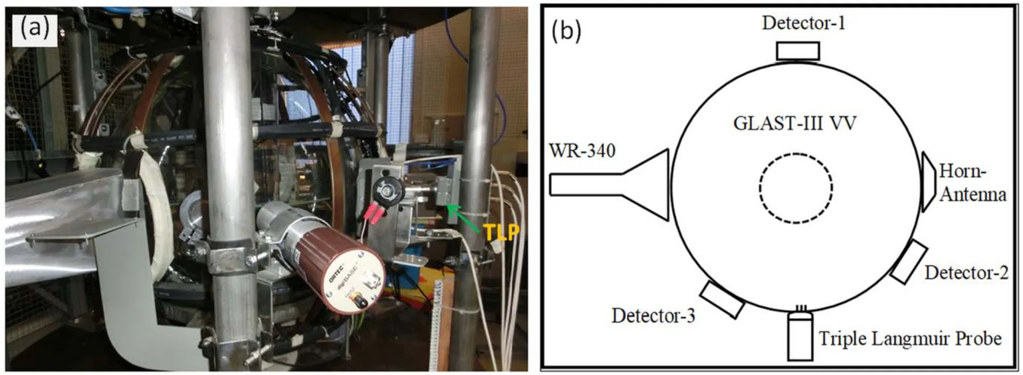
Figure 1.GLAST-III (a) experimental setup and (b) its schematic diagram (top view).
Wave–particle interactions need to be carefully considered to interpret microwave-assisted plasma pre-ionization.Cyclotron absorption is the main mechanism responsible for wave absorption.When the frequency of the incident wave matches the cyclotron frequency of the charged particle,resonance absorption takes place, in which wave energy is transferred to the particle.The cyclotron’s resonant frequency isf=enBT2πme,wheremeis mass of the electron andnis the harmonic number.Resonance absorption of 2.45 GHz microwaves takes place at a position where the TF strength is 0.0875 T.For the low-field-side microwave launch, fundamental resonance absorption is possible for the O-mode, but is not accessible for the X-mode, due to right-hand cutoff in the cold-plasma limit.For X-mode polarization, resonance absorption is possible for the low-field-side launch, and it is called upper hybrid resonance (UHR) absorption [23].
Microwaves with a typical frequency of 2.45 GHz have been frequently used for ECRH-assisted plasma start-up in several tokamaks, e.g.KAIST-Tokamak [24] and SUNIST[25,26].In the LATE device[27],plasma formation has been achieved non-inductively by electron cyclotron heating(ECH) alone.Recently, plasma pre-ionization experiments have been carried out in the VEST device using a pure toroidal field to investigate efficient plasma pre-ionization [28].However, most of these studies have been performed on tokamaks with metallic vessels,which have multiple passages for the incident microwaves and result in mode mixing due to multiple reflections from the chamber’s wall.Therefore, a complete understanding of the underlying mechanism of microwave-assisted plasma pre-ionization (with pure modes)is still an unresolved issue.GLAss Spherical Tokamak(GLAST-III)provides a unique opportunity to investigate the characteristics of pure microwave modes in the plasma startup.In GLAST-III pre-ionization experiments,microwaves are launched into the vacuum vessel (VV) through the WR-340 waveguide(with different orientations),leading to O-,X-,and M-modes.The plasma breakdown characteristics are thoroughly investigated for these modes at different toroidal-field(TF) strengths and hydrogen pressures by measuring the plasma electron temperature(Te) ,electron-number density,and microwave absorption, and by analysing the plasmadischarge images.
The rest of the paper is organized as follows.Section 2 describes the experimental setup of the GLAST-III preionization system.The plasma measurement techniques are presented in section 3.Section 4 discusses the main results of the plasma pre-ionization experiments.Finally,a summary of the key findings is presented in section 5.
2.Experimental setup
GLAST-III is a spherical tokamak based on a Pyrex VV[29, 30] with a major radius =R0.2 m, and a minor radiusa=0.1 m.Microwaves are injected into the chamber through a rectangular waveguide(WR-340),as depicted in figure 1(a).For pulsed-mode operation, the microwave source was indigenously developed by modifying a domestic microwave oven circuit [31].A 1 kW microwave source (operating at 2.45 GHz) is installed at GLAST-III.Three pin-diode loops are installed 120 degrees apart outside the chamber to detect the absorption in the chamber.This arrangement of diodes ensures the measurement of the absorption pattern at different locations within the chamber.A pyramidal horn antenna is placed opposite the waveguide to detect the microwaves after they have passed through the plasma.The horn is connected to a Fieldfox combination analyser (N9916A) to measure the absorbed frequency components of the microwave signal.In addition, a triple Langmuir probe (TLP) is placed at the equatorial plane to measure the electron temperature, as shown in figure 1.The locations of the waveguide, horn antenna, pin diodes, and TLP are depicted in the schematic diagram (top view) of GLAST-III (figure 1(b)).
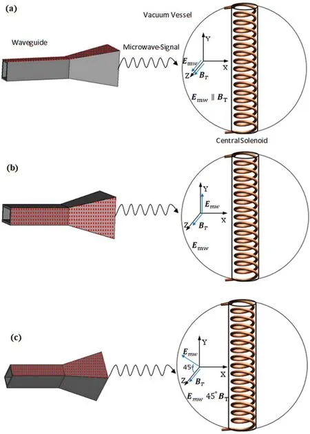
Figure 2.Schematic diagram of (a) O-mode, (b) X-mode, and (c) M-mode microwave signals injected into GLAST-III.
Microwaves are launched into the chamber from the lowfield side for three different orientations of the waveguide,as depicted in figure 2.In the case of the O-mode,the waveguide is placed such that the microwaves’ electric fieldEmwis parallel to the toroidal magnetic fieldBT.The X-mode is generated by rotating the waveguide such thatEmwis perpendicular toBT.The M-mode is obtained by adjusting the waveguide to an angle of 45 degrees with the horizontal plane.
3.Measurement of plasma parameters

Figure 3.Schematic diagram of(a)triple Langmuir probe circuit,(b)comparison of its potential and(c)image of the triple Langmuir probe installed at GLAST-III.
Langmuir probes are widely used for local measurements of plasma properties including plasma density,plasma potential,and electron temperature [32–34].For transient events, such as those observed during the initial discharges of GLAST-III,a triple probe is the most suitable technique,instead of single or double probes.The TLP tips comprise three cylindrical tungsten wires, 0.003 m in length and 0.002 m apart [34].A schematic diagram of a typical TLP circuit, probe potentials,and the TLP installed at GLAST-III are shown in figure 3.LetV,1V2,andV3be the potentials at probe-1,probe-2,and probe-3, respectively.The potential difference across probe-1 and probe-2 isV12and that across probe-1 and probe-3 isV13,which can be expressed as follows:

The current flowing into each probe tip can be written as follows:

whereIioandIeoare the ion and electron currents andkis the Boltzmann constant.According to Kirchhoff’s current law,the net current of positive ions and electrons flowing into the system from the plasma must be zero at any time instant,
Solving the above equations,we finally get an expression that allows the calculation of the plasma temperature.Note that we have assumed that the bias voltageV13is sufficiently large(eV13≫kTe)[33, 35].

whereVfis the floating potential measured by an unbiased probe.The plasma-edge temperature is calculated using the above equation and the TLP experimental data.Using this temperature expression, the electron edge density can be calculated as follows:
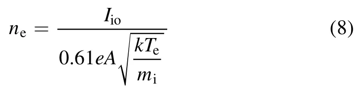
wheremiis the ion mass,Ais the collection area of the probe,andIiois the ion saturation current.Using equations (3) and(4), the ion saturation current is determined as follows:
HereI13is the probe current.The electron temperature and number density at the plasma edge are calculated using the above equations and the TLP experimental data.

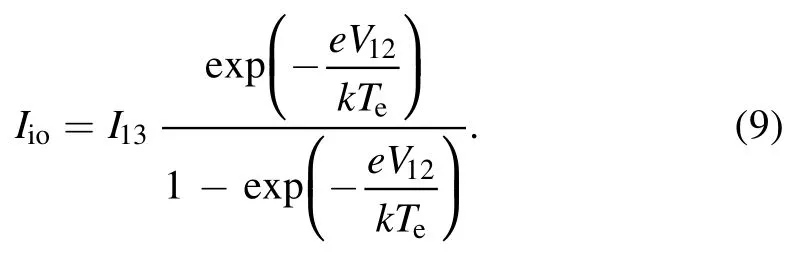
Figure 4.Time evolutions of the electron temperature at the plasma edge in (a) the O-mode, (b) the X-mode, and (c) the M-mode for various filled gas pressures (0.03 Pa to 4 Pa) at(B0=0.05 T) .
4.Results and discussion
The plasma pre-ionization characteristics of the GLAST-III device are investigated for the O-, X-, and M-mode polarizations with different hydrogen gas pressures and toroidalfield strengths in the absence of a poloidal magnetic field.The application of a toroidal magnetic field without a poloidal field component ensures pure microwave modes.The key plasma breakdown properties are measured in terms of the microwave absorption signal, fast camera images, and the electron temperature at the plasma edge (Te).Figure 4 shows the time evolution ofTefor the O-, X-, and M-modes over a broad range of hydrogen pressures (0.01 to 4 Pa) with a toroidal magnetic-field strength at the centre of the vacuum vesselB0( )of about 0.05 T.In the case of O-mode discharge,efficient plasma pre-ionization (with a maximum peak value ofTe) is achieved at a hydrogen pressure of 0.05 Pa, beyond which, no absorption occurs (figure 4(a)).In all three polarizations, a higher value ofTeis observed at low pressures,because the collision probability becomes low for larger available mean free paths, resulting in higher electron energy gain.In the case of X-mode polarization (figure 4(b)), the temporal profile ofTeis relatively broader,and its peak value is higher than that of the O-mode.
Figure 5.Time evolutions of the electron temperature at the plasma edge in (a) the O-mode, (b) the X-mode, and (c) the M-mode for various filled gas pressures (0.01 Pa to 4 Pa) at(B0=0.075 T).
This variation may arise from the difference in the waveheating mechanisms.In the case of the O-mode, electron cyclotron resonance(ECR)absorption is clearly demonstrated at the resonance location near the inboard side,whereas in the case of the X-mode, it seems that UHR absorption may be responsible for the plasma breakdown near the plasma-edge region.This is later elucidated by the microwave absorption signal and the fast camera images.A similar behaviour in an ECR plasma was recently observed by Yuet al[36].In the case of the mixed-mode polarization (figure 4(c)), theTetemporal profile is broad and its peak value is higher than that of the O-mode but smaller than that of X-mode.These results suggest that in the small TF(B0=0.05 T) case, X-mode polarization is favourable for efficient plasma pre-ionization at low filled gas pressures (0.05 Pa).
In figure 5, the above-mentioned polarization study s repeated for a stronger toroidal magnetic field(B0=0.075 T),which shifts the resonance layer location towards the centre at ~0.06 m from the inner wall.Compared to the smaller TF case (figure 4), the following variations are observed: the peak value ofTeincreases further for the three launching modes.The optimum value of hydrogen pressure for efficient plasma pre-ionization is observed to decrease to 0.03 Pa, after which, no absorption occurs.By increasing the TF strength, the resonance layer’s location is shifted towards the VV centre, resulting in relatively fewer particle collisions with the inner wall, which is probably responsible for the improved pre-ionization,compared to the smaller TF case.In O-mode polarization,the time evolution ofTedisplays a twostep increase at the optimum filled gas pressure.TheTetemporal profile is broader in the X-mode polarization (the same as that observed in figure 4).A comparison of theTetime evolution for the three microwave modes shows that the X-mode is favourable for plasma start-up.

Figure 6.Time evolutions of the electron temperature at the plasma edge in (a) the O-mode, (b) the X-mode, and (c) the M-mode for different filled gas pressures (0.01 Pa to 4 Pa) at(B0=0.1 T) .
The toroidal magnetic-field strength is further increased(B0=0.1 T) ,which shifts the resonance layer nearer to the centre of the VV(~0.09 m from the inner wall).The electron temperature at the plasma edge is plotted for the three modes at different hydrogen filled pressures (figure 6).The peak values ofTeare considerably smaller than those in the intermediate toroidal magnetic field case (figure 5) for all three polarizations.The peak values ofTeare comparable for all modes at the optimum hydrogen pressure of 0.03 Pa.However,theTetemporal profile is relatively broader in the case of the X-mode.

Figure 7.Time evolutions of the microwave signal without plasma(Microwave signal 1), with plasma (Microwave signal 2), the toroidal coil current and the corresponding Te at a hydrogen filled pressure of 0.03 Pa and with B0=0.075 T for (a) the O-mode, (b)the X-mode, and (c) the M-mode.
To further elucidate the microwave absorption in the O-,X-, and M-modes, the time evolution of theTe,microwave reference signal under vacuum conditions (Microwave signal 1), the microwave absorption signal (Microwave signal 2),and the toroidal coil current are plotted in figure 7.A comparison of the three modes is presented at an intermediate value of TF(B0=0.075 T).It can be seen thatTeincreases sharply as soon the microwave absorption is initiated.In the X-mode(figure 7(b)),microwave absorption is observed for a longer duration,compared to that in the O-mode(figure 7(b))and the M-mode (figure 7(c)).This behaviour of the microwave absorption signal is consistent with the time evolution ofT.eA comparison of the three modes suggests that the X-mode is favourable for plasma start-up where the microwave absorption is significant, and that it is effective for a longer duration.
These experimental results are summarized in table 1,which shows that the electron temperature at the plasma edge is maximal in the intermediate toroidal magnetic-field case(B0=0.075 T) for all three modes.It may be noted that the resonance layer position varies when the TF strengths change.In the small TF case, resonance absorption takes place at~0.02 m from the inner wall.When the magnetic field is increased to(B0=0.075 T ) ,the resonance layer shifts towards the centre at ~0.06 m from the inner wall,whereas in the stronger TF case, the resonance layer shifts nearer to the centre at ~0.09 m from the inner wall.Thus,the intermediate toroidal magnetic field (with a resonance layer position in between the centre of the VV and the inner wall)is favourable for achieving efficient plasma start-up at the optimal working gas pressure.In all three TF cases, the microwave absorptionduration is the longest for X-mode polarization, compared to those of the O- and M-modes.

Table 1.Comparison of Te values and microwave absorption durations in the X-, O-, and M-modes.

Figure 8.Time evolutions of electron-number density at the plasma edge for(a)the O-mode,(b)the X-mode,and(c)the M-mode with a filled gas pressure of 0.03 Pa at(B0=0.075 T) .
To further validate our results,we measured the electronnumber densityneat the plasma edge with the help of TLP data and equation (8).Time evolutions ofnefor the three microwave polarizations at the intermediate TF strength and the optimum filled gas pressure are plotted in figure 8.In all cases, the peak values ofneare found to be less than the cutoff density of this ECR plasma,which can be calculated asne=ε0meωc2e2=7.5 × 10¹⁶m−3,whereε0is the permittivity of free space,medenotes the electron mass,ωcis the angular frequency of the incident microwave,andestands for the electron charge.It can be observed that the temporal profile of the electron-number density is broader in the case of the X-mode(figure 8(a)),with a peak value higher than those of the O- and M-modes.Based on the time evolutions of the electron temperature and number density at the plasma edge and the microwave absorption signal, the X-mode appears to be the better option for plasma pre-ionization at the optimum hydrogen gas pressure.
Microwave absorption in the O-,X-,and M-modes at the optimum hydrogen pressure of 0.03 Pa (corresponding to figure 7) is further delineated by the plasma-discharge patterns,as depicted in figure 9,where each snapshot is ~0.2 ms in duration.Figure 9(a) shows the evolution of plasma preionization in the O-mode, where the cyclotron resonance absorption is initiated at time =t1.8 ms.The glow intensity gradually increases and reaches a maximum value at timet=3.6 ms.After several snapshots, the plasma discharge spreads towards the edge region.The evolution of the plasma pre-ionization observed in the camera images is consistent with the evolution ofTe(figure 7(a)).In the X-mode, plasma pre-ionization starts early at time =t1.2 ms, however, images are presented at a later time, =t1.8 ms, for the sake of comparison (figure 9(b)).Microwave absorption appears to occur via UHR near the plasma-edge region.The plasma glow intensity grows abruptly and spreads towards the VV centre.The plasma pre-ionization duration is longest (1.2 ms to 5.2 ms)in the case of the X-mode,which is consistent with theTetime evolution and the longer microwave absorption signal (figure 7(b)).The M-mode characteristics exhibit features of both the X-and O-modes,as shown in figure 9(c).In this case, plasma discharge starts earlier, at almost the same time as that of the X-mode (t=1.2 ms ) ,with a lower glow intensity.Initially, microwave absorption seems to take place at the resonance location (at ~0.06 m from the inner wall),which is consistent with the early dip in the microwave absorption signal.At a later stage,the discharge spreads to the plasma-edge region (similarly to the O-mode discharge).These results confirm that the X-mode is the best option for plasma pre-ionization for a low-field-side launch in the coldplasma limit,which is consistent with the previous prediction by R Prater [23].
The effect of the applied TF strength on the plasma preionization process is further confirmed by examining the location of microwave resonance absorption in a typical O-mode polarization, as shown in figure 10.The microwave resonance absorption at the fundamental harmonic is near the inboard side in the small TF case (figure 10(a)).The location of the resonance layer is shifted towards the outboard side as the TF strength is increased.It can be observed that efficient plasma pre-ionization is achieved in the case of the intermediate TF, in which microwave resonance absorption occurs near the VV centre.
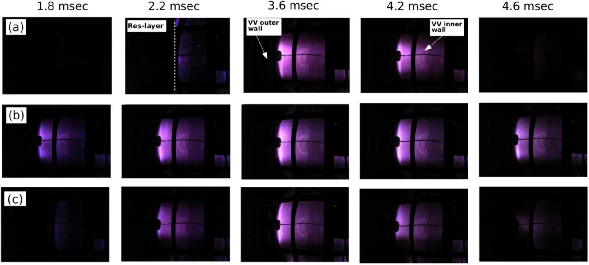
Figure 9.Time sequence of high-speed camera images during the plasma pre-ionization experiments (same case as shown in figure 7) for(a) the O-mode, (b) the X-mode, and (c) the M-mode.
5.Summary
In this work, ECRH-assisted plasma pre-ionization is experimentally explored by optimizing microwave polarization(i.e.,the O-,X-,and M-modes),the spatial position of the resonance layer (by changing the TF strength) and the working gas pressure.The plasma pre-ionization behaviour is investigated by examining electron temperature, electron density, microwave absorption, and high-speed camera images.Distinct plasma-discharge behaviour is observed for the three microwave polarizations.ECR absorption is evidently observed in the case of the O-mode,whereas in the case of the X-mode, wave absorption occurs near the outboard side,possibly via upper hybrid resonance absorption.In the M-mode launch, plasma discharge shows signatures of both the X-mode and the O-mode.A comparison of the microwave polarizations suggests that the X-mode is the best candidate for efficient plasma pre-ionization.An optimal working gas pressure is identified for efficient plasma pre-ionization,which changes with the applied TF strength (0.05 Pa for the weak TF case and 0.03 Pa for the intermediate and strong TF cases).These results signify that efficient plasma pre-ionization can be achieved with X-mode polarization in small tokamaks.These findings will be useful in optimizing the input parameters for microwave-assisted tokamak start-up.
Acknowledgments
We are thankful to the GLAST team for their unstinting support in making this work possible.This project was partially supported by a Grant-in-Aid from the Planning Commission, Government of Pakistan and IAEA Co-ordinated research project (CRP-F13018) under research grant PAK-22840.

Figure 10.Resonance layer in(a)weak(B0=0.05 T)(b)intermediate(B0=0.075 T)and(c)strong TF(B0=0.1 T)cases for O-mode launch.
ORCID iDs
Ahmad ALI https://orcid.org/0000-0002-8301-0188
杂志排行

Plasma Science and Technology的其它文章
- Energy and flux measurements of laserinduced silver plasma ions by using Faraday cup
- Experimental investigation on DBD plasma reforming hydrocarbon blends
- Research on active arc-ignition technology as a possible residual-energy-release strategy in electromagnetic rail launch
- Distinguish Fritillaria cirrhosa and non-Fritillaria cirrhosa using laser-induced breakdown spectroscopy
- On abnormal behaviors of ion beam extracted from electron cyclotron resonance ion thruster driven by rod antenna in cross magnetic field
- Research on quinoline degradation in drinking water by a large volume strong ionization dielectric barrier discharge reaction system