Design of sextuple-mode triple-ring HTS UWB filter using two-round interpolation*
2021-05-24MingEnTian田明恩ZhiHeLong龙之河YouLan蓝友LeiLeiHe贺磊磊andTianLiangZhang张天良
Ming-En Tian(田明恩), Zhi-He Long(龙之河), You Lan(蓝友),Lei-Lei He(贺磊磊), and Tian-Liang Zhang(张天良),†
1School of Aeronautics and Astronautics,University of Electronic Science and Technology of China,Chengdu 611731,China
2Department of Mechanical Engineering,City University of Hong Kong,Kowloon,Hong Kong SAR,China
Keywords: HTS filter,ring resonator,sextuple-mode,two-round interpolation,ultra-wideband(UWB)
1. Introduction
The ultra-wideband(UWB)wireless communication system is promising because it can provide fast response speed and high positioning accuracy required by many military and civilian applications. And the UWB bandpass filter, the key building block, in the UWB system has aroused the great interest of researchers. The microstrip ring resonator with many attractive merits,including the low radiation loss,high-Q factor, compact size, split modes, and sharp rejection skirts, is widely employed in the development of the UWB bandpass filters. Ring resonators possess a variety of shapes, such as circles,[1–5]rectangles,[6–9]and triangles,[10]among which the rectangular ones have greater research value due to the easiness of design and processing. The UWB filters based on rectangular single-ring resonators have been extensively studied.However,the in-band return loss or the selectivity of the passband is not better than the counterpart of the high-order UWB filters with a larger size,due to the number of resonant modes excited by these single-stage ring resonators usually being less than six. Furthermore,the upper stopband suppression performance of the ring resonator UWB filters is still worth investigating.
In this paper, we design a compact triple-ring resonator loaded with three sets of stepped-impedance open stubs to realize a UWB filter with better return loss and upper stopband. This multi-mode resonator can give rise to six modes,and two more resonances can be generated by the interdigitalcoupling line(ICL)structure.[11]The initial dimensions of the designed UWB filter are determined by the proposed practical two-round interpolation method.
2. Design of UWB filter
Figure 1 shows the proposed triple-ring sextuple-mode UWB filter working in a range of 3.1 GHz–10.6 GHz, the commercial UWB communication frequency band which is assigned by the Federal Communications Commission(FCC).The three groups of stepped-impedance open stubs are specially designed for miniaturization. Typically, the resonant modes are evenly distributed within the passband, and taking into account the effect of the transition sidebands,we allocate the six resonant modes at 3.4 GHz, 5 GHz, 6.5 GHz, 8 GHz,9.2 GHz, and 10.4 GHz, among which the fundamental odd and even modes fo1(3.4 GHz) and fe1(5 GHz) are particularly important and will be used to determine the filter initial dimensions.
Since the proposed UWB filter is symmetrical in the vertical and horizontal directions, we apply the even–odd-mode method to simplifying the analysis. When considering the resonant frequencies of odd modes, the perfect electric wall can be introduced into the symmetric plane. Figure 2(a) shows an odd-mode equivalent circuit. For the calculation of evenmode resonances, the plane of symmetry can be regarded as the perfect magnetic wall, and the corresponding even-mode equivalent circuit is depicted in Fig. 2(b). Also, the potential of the upper and lower symmetric nodes are equal, i.e.,the plane of stubs loaded in the central ring can be considered as an open-circuit, and therefore the improved odd- and even-mode equivalent circuits can be obtained as shown in Figs. 2(c) and 2(d). And for the convenience of analysis, the three pairs of stepped-impedance stubs are simplified into the uniform-impedance stubs,which finally will be converted into the stepped-impedance ones again. However, these two circuits in Figs. 2(c) and 2(d) are still rather complex and difficult to analyze. They can be further simplified as shown in Figs.2(e)and 2(f)based on the theoretical analysis of the input voltage and input current as well as the potentials.

Fig.1. Proposed sextuple-mode UWB filter layout.
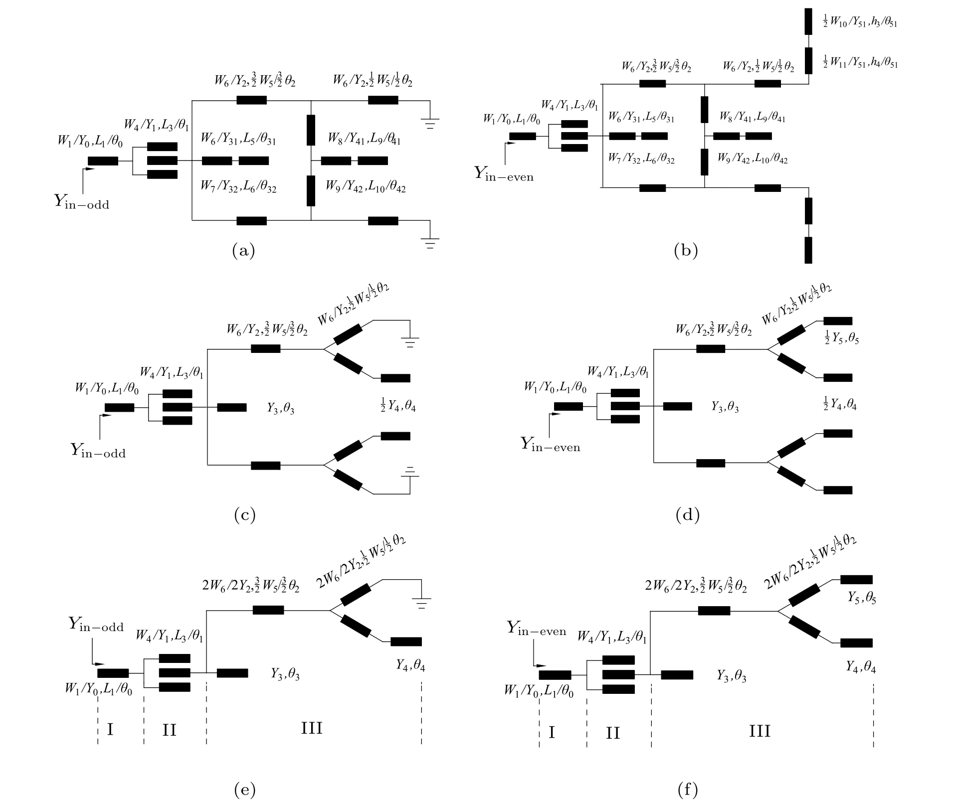
Fig.2. Odd–even-mode analyses of[(a),(c),and(e)]odd-mode equivalent circuits and[(b),(d),and(f)]even-mode equivalent circuits.

Table 1. ABCD matrices for basic transmission line models.
We utilize the ABCD matrices and the proposed tworound interpolation method to obtain the initial values of the filter.The ABCD matrices for the basic transmission line models used in this paper are listed in Table 1. According to the series transmission line models,we can calculate the transmission matrix MIfor the part I in Fig.2,and the ABCD transmission matrix MIIfor the ICL structure can be acquired from Ref.[12].
The core of the design method is the two-round interpolation.The first round is to determine the value for the most critical parameter by setting special values for trivial parameters to simplify the calculation and then by applying the interpolation approach under the odd- and even-mode resonance conditions. In this design,θ2is a key parameter. To explain why θ2has a greater influence on all modes than other parameters,the mathematical derivations of all modes are given in Table 2.According to the odd–even-mode analysis,the two equivalent circuits of Figs. 2(c) and 2(d) can be further simplified into those in Figs. 3(a)–3(d), respectively, because the two circuit diagrams of Figs.2(c)and 2(d)are still symmetrical about the horizontal axis.The four resonators in Figs.3(a)–3(d)can generate multiple resonant modes. Here, only the seven modes used in this paper are derived. None of those modes that have frequencies higher than 20 GHz but no effect on the filter is considered. It can be seen from Table 2 that only θ2exists in all the equations under the seven resonance conditions,which indicates that θ2is the most important parameter. The second round is to determine the values for some secondary parameters(θ3, θ4, and θ5here)by adjusting some preset values for trivial parameters in the first round and solving the generation conditions of transmission zeros(TZs).
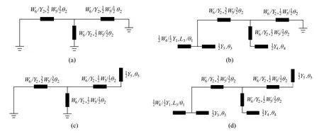
Fig.3. Further simplified equivalent circuits based on Figs.2(c)and 2(d).
The specific initial value acquisition process of the firstround interpolation is given below. The ring resonator is a full-wavelength resonator, so θ2is equal to a quarter of the wavelength corresponding to the center frequency, which is 1.59. And Y2is the characteristic admittance corresponding to 0.2 mm, the frequently-used microstrip line width.Y2=0.014 S.For the convenience of description,we suppose Y2=K1Y3=K2Y4=K3Y5,θ2=B1θ3=B2θ4=B3θ5=B4θ1.To facilitate the odd–even-mode analysis,we here in this work let K1=K2=K3=2. Then,according to the preset resonance frequencies, the odd-mode equivalent circuits in Table 2 and their resonance condition equations,B3can be calculated and equal to 1. Similarly, based on the preset resonance frequencies,even-mode equivalent circuits in Table 2,their resonance condition equations,and B3=1,the remaining Bivalues can be computed,namely B1=0.4,B2=0.3,and B4=1. To reduce the deviation,the value of Kiand Biare substituted into the original formulas again,and the resonance frequencies obtained are listed in Table 2. These frequency values obtained by the backward derivation are consistent with the preset frequencies. Therefore,the accuracy of Kiand Biare guaranteed.The length of the filter ports is taken as a constant value of 3 mm for connecting ports to connecters by using the golden wire,and the width of ports is 0.48 mm corresponding to 50 Ω.For a strong coupling,the line and slot width of ICL are chosen to be 0.1 mm and 0.03 mm under the limited processing accuracy.

Table 2. Derivation of used seven resonant modes.

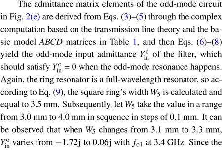


The TZs generated by the stepped-impedance stubs are related to the frequencies of the resonances. The loaded stepped-impedance stubs can not only generate the resonances through the first round of interpolation but also can adjust the TZ frequency through the second round of interpolation. In other words,the stepped-impedance stubs affect both the resonance frequency and the TZ frequency. When the electrical lengths of the centrally-loaded stubs are a quarter of the wavelength,the center of the resonator can be equivalent to grounding, and therefore a TZ can be generated. And the frequency of the TZ can be derived from


Table 3. Initial values for proposed UWB filter.
Here,the TZs generated by the stepped-impedance stubs are computed to be 13.5 GHz, 17.13 GHz, and 20 GHz, respectively. Note that the parasitic effect of the microstrip line and the mutual coupling of the filter structure itself cannot be ignored due to the high stopband frequency.
Finally, the uniform-impedance stubs are converted into the stepped-impedance ones,where a high-impedance ratio is employed for miniaturization.The low-impedance line parameters are given according to Eq.(17),with the high-impedance line parameters fixed. All the initial values of the proposed UWB filter are listed in Table 3, where the electrical lengths are all based on the center frequency. It should be noted that B1, B2, and B3have infinite solutions, and only one set of solutions is given here. The two-round interpolation method used here can be applied to other odd–even-mode filter designs where the conditions of odd- and even-mode resonances and TZs generation are required to be analyzed.This approach can effectively improve the design efficiency by reducing complex calculations while ensuring relatively high accuracy.

Fig.4. (a)Changing trends of even and odd modes and TZs with L5,and(b)S-parameter varying with frequency for three values of L5 on the high-order mode fo4.
The proposed filter has the characteristic of a wide upper rejection band,and the parameter L5is especially important in suppressing the out-of-band spurious perturbation. The value of L5can be obtained by converting the uniform-impedance stub into the stepped-impedance one. The input admittance of the uniform-impedance stub is Y3and that of the steppedimpedance one is Yb. Y3=0.014 S, and the electrical length θ3=0.64. To facilitate the design and processing, the physical dimensions of the stepped-impedance stub are set to be W6=0.2 mm,W7=0.6 mm,and L6=0.5 mm. By converting these dimensions into the electrical lengths, which are subsequently substituted into Eqs.(20)–(23),we obtain θ31=0.31,and then we convert θ31(L5) into a physical size of 0.7 mm again.
Through the above analysis and calculations,all the initial values are obtained.To further verify the reliability of the tworound interpolation approach, verification through simulation is conducted. The important parameter L5is selected here to perform the verification. Let L5take multiple values, so that the changing trends of resonance modes and TZs are more intuitive as shown in Fig. 4(a). When L5is equal to around 0.68 mm, f04and fTZ3coincide, which means that f04is rejected by fTZ3. This high-mode suppression effect can also be observed in Fig.4(b). And according to the above calculation,L5is 0.7 mm,indicating the good agreement between simulation and theoretical calculation,which confirms the reliability of the two-round interpolation method.
3. Fabrication and measurements
The proposed UWB filter is designed and optimized by full-wave electromagnetic simulation software IE3D, and the finally obtained optimal dimensions are listed in the caption of Fig. 6. According to the filter pattern on the mask, the corresponding circuit is etched on the 0.5-mmthick YBCO/MgO/YBCO high-temperature superconducting thin film with a size of 25.10 mm × 13.63 mm and a dielectric constant of 9.8 by the photolithography technology. Figure 5 shows the fabricated filter consisting of a superconducting thin-film circuit, metal shielding box, and SMA connectors. To ensure a good electrical connection between the circuit and the pins of the connectors, the gold covered on the 50-Ω microstrip line is reserved.
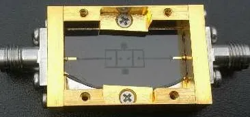
Fig.5. Fabricated HTS UWB filter.
Figure 6 shows the test and simulation responses of the filter. The transmission poles in the passband are changed from six to eight due to the utilization of ICL.[6]The measured results are well consistent with the simulated ones. The passband covers 3.1 GHz–10.6 GHz; the maximum insertion loss within the passband is only 0.42 dB, and the reflection is better than −15.6 dB.The upper stopband with attenuation greater than 25 dB extends to 19 GHz,and most of the upper stopband is inhibited to approximately −40 dB. Besides, the in-band group delay is less than 2 ns.
Table 4 presents the comparison of the filter proposed in this work with the single-stage multi-mode UWB filters in other references. Our filter shows superiority in the insertion loss,return loss,and upper stopband rejection characteristics.
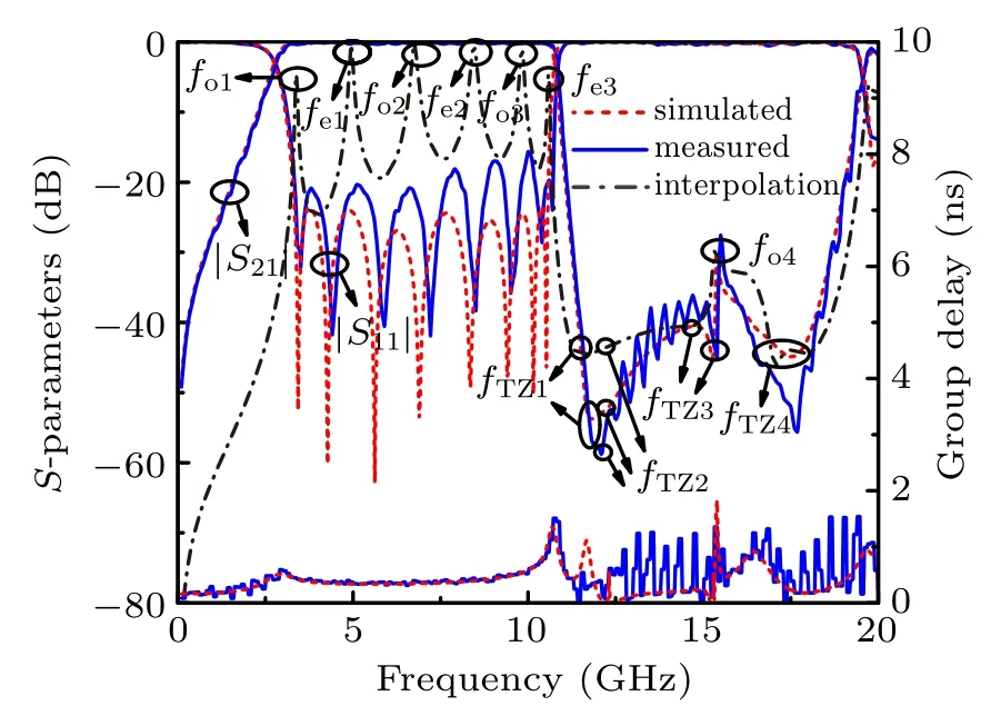
Fig. 6. Simulated and measured results. The finally obtained dimensions are as follows: W1 =0.48,W2 =0.11,W3 =0.07,W4 =0.12,W5 =3.96,W6 =0.17, W7 =0.58, W8 =0.10, W9 =0.48, W10 =0.20, W11 =1.27,L1 =3.00, L2 =5.12, L3 =4.74, L4 =8.13, L5 =0.68, L6 =0.50, L7 =2.02, L8 =3.06, L9 =0.47, L10 =0.50, h1 =0.47, h2 =0.55, h3 =0.31,h4=1.09,and S1=0.03(all in units of mm).

Table 4. Comparison of our proposed filter with the reported UWB filters.
4. Conclusions
Based on the ring resonator and stepped-impedance open stubs,a sextuple-mode ring resonator is proposed and used in a single-stage UWB filter design. The good in-band return loss,right band-edge selectivity,and upper stopband rejection are achieved because of the efficacy of this resonator and ICL structure. The proposed two-round interpolation method exhibits the practicability in the odd–even-mode filter designs.
杂志排行
Chinese Physics B的其它文章
- Corrosion behavior of high-level waste container materials Ti and Ti–Pd alloy under long-term gamma irradiation in Beishan groundwater*
- Degradation of β-Ga2O3 Schottky barrier diode under swift heavy ion irradiation*
- Influence of temperature and alloying elements on the threshold displacement energies in concentrated Ni–Fe–Cr alloys*
- Cathodic shift of onset potential on TiO2 nanorod arrays with significantly enhanced visible light photoactivity via nitrogen/cobalt co-implantation*
- Review on ionization and quenching mechanisms of Trichel pulse*
- Thermally induced band hybridization in bilayer-bilayer MoS2/WS2 heterostructure∗
