High efficiency and broad bandwidth terahertz vortex beam generation based on ultra-thin transmission Pancharatnam–Berry metasurfaces*
2021-05-24WenyuLi李文宇GuozhongZhao赵国忠TianhuaMeng孟田华RanSun孙然andJiaoyanGuo郭姣艳
Wenyu Li(李文宇), Guozhong Zhao(赵国忠), Tianhua Meng(孟田华), Ran Sun(孙然), and Jiaoyan Guo(郭姣艳)
1Department of Physics,Capital Normal University,Beijing Key Laboratory for THz Spectroscopy and Imaging,Key Laboratory of THz Optoelectronics,Ministry of Education,Beijing 100048,China
2Institute of Solid State Physics,Shanxi Datong University,Datong 037009,China
Keywords: metasurface,terahertz vortex beam,Pancharatnam–Berry phase element,conversion efficiency
1. Introduction
The angular momentum consists of two parts: spin angular momentum (SAM) related to polarization states, and orbital angular momentum (OAM) relevant to phase distributions of the optical field.[1,2]The SAM represents the spin feature of photons, while the OAM indicates the orbital rotation of photons.[3,4]Vortex beams,which have helical wavefronts and orbital angular momentums,are being given extensive attention.[5–8]A vortex beam has a spiral phase structure exp(ilϕ),where l is the topological charge and ϕ is the angular coordinate.[9,10]OAM vortex beams have a large number of applications in different fields, such as the communication system,[11,12]optical micro-manipulation,[13]super resolution imaging[14]and so on,due to their distinctive properties.
Meanwhile, researchers have paid close attention to generating OAM vortex beams. The conventional methods for generating vortex beams involve mainly spiral phase plates,[15]computer generated holograms,[16]and so on.However, these means are all based on the accumulated optical path, and hence the device designed may suffer from a bulky shape.[17]It is worth mentioning that the vortex phase plates(VPPs)based on metasurfaces can provide phasediscontinuities to control and manipulate the propagation of electromagnetic waves.[18–23]The metasurfaces can provide abrupt phase changes based on two classifications. The first is based on the resonance of designed scatters,[20–22]and the second utilizes Pancharatnam–Berry(P-B)phase elements.[23–27]The majority of recent vortex beam generators use these two methods. In 2017,Luo et al.[26]designed ultra-thin P-B metasurfaces with a thickness of approximately λ/8,which added effective magnetic responses and could generate vortex beams with high efficiency. The unit cell is composed of three metallic structures separated by two dielectric spacers. In 2019,Li et al.[27]proposed a vortex beam generator based on reflective P-B metasurfaces in THz, and the unit cell consisted of a metal-dielectric-metal three-layer structure. The efficiency was 86% in a frequency range of 0.8–1.4 THz. In 2019,Tang et al.[24]used multiple plasmon resonances to increase the efficiency significantly. The high amplitude of transmission and similar slopes of phase responses in a broad bandwidth could be controlled by the open angle and rotation angle of unit cells, respectively. Despite the generation of vortex beams using metasurfaces,these vortex generators have a complex and multilayer structure, as well as integration difficulties. Moreover, some generators work in the reflective direction,which is not fit for practical applications. A singlelayer metasurface with a thickness of about 0.001λ is designed in this study,which is easier to fabricate and integrate. In addition, the phase covering 2π could be achieved only by adjusting the rotation angle of the unit cell, which replaces the tedious design proposed in other reports.
In this paper,ultra-thin metasurfaces are used to generate THz OAM vortex beams. The OAM with various topological charges of l is realized using the P-B phase element, and the maximal cross-polarization conversion efficiency could approach the theoretical limit in whole working broadband. At the same time, the propagation behavior of the emerged THz vortex beam is analyzed in detail.The results demonstrate that this proposed method could generate an arbitrary value of THz vortex beam; at the same time the beam shows stable propagation characteristics and keeps a high fidelity over a broad frequency range.
2. Theoretical analysis
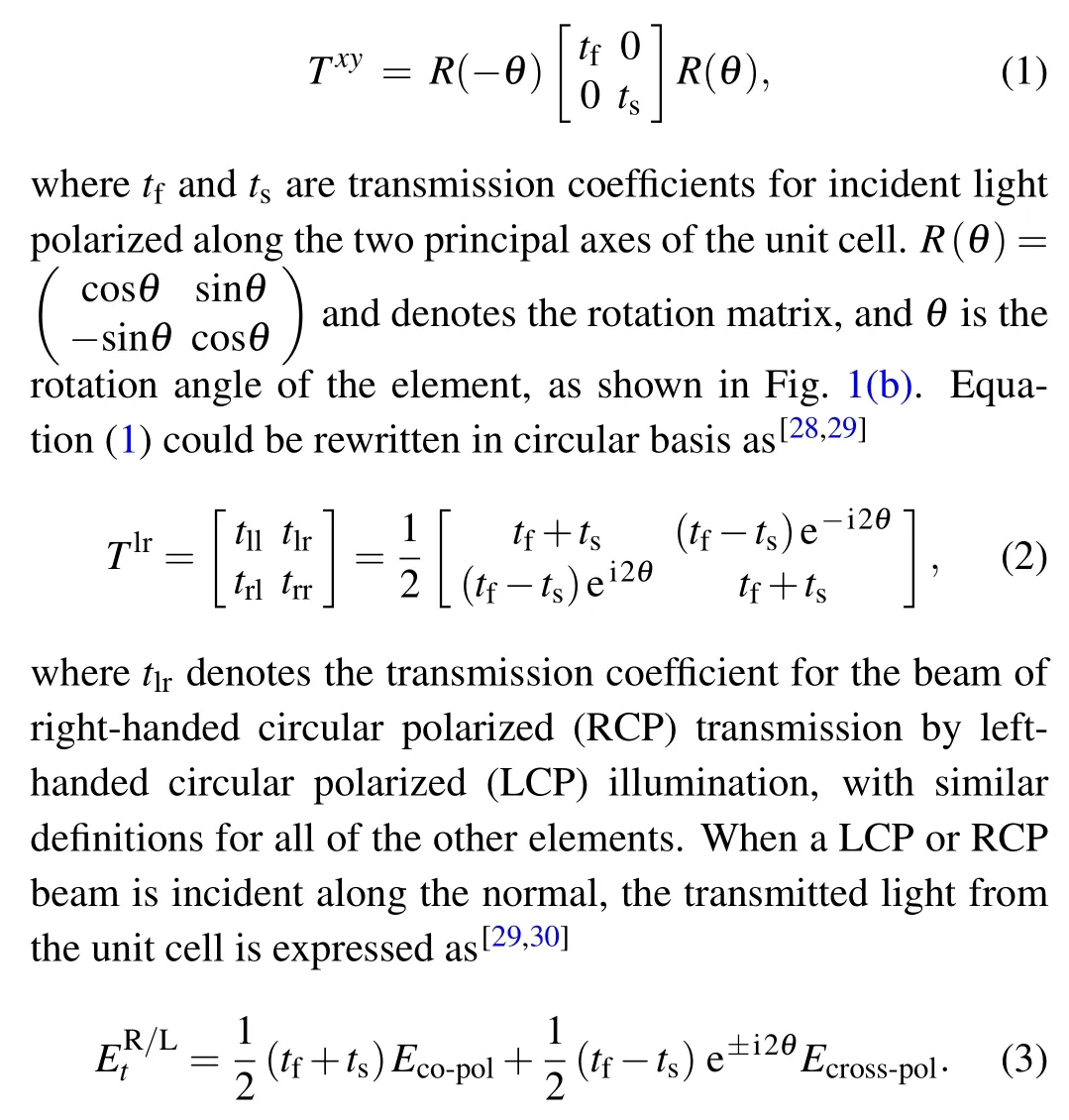
The proposed metasurfaces are made of a series of unit cells arranged regularly. To obtain the required phase distributions and maintain constant amplitudes,it is necessary to modify the wavefront by rotating unit cells. The unit cells,that is,P-B phase elements, can be designed for the THz functional components. The designed metasurface is shown in Fig.1(a).The transmission matrix of the unit cell in the xy coordinate system is represented by Jones calculus,which can be written as[28,29]
Equation(3)demonstrates that the transmitted field from a PB metasurface consists of two polarization cases. The Eco-polexpresses that the polarization state is the same as the original incident wave. The Ecross-polpossesses inverse handedness and a phase shift of ±2θ, where the sign ‘±’ corresponds to the chirality of the incident beam.[31]This attached phase is called the P-B phase, which is a spin-dependent geometrical phase.[28–31]By rotating the P-B phase elements,the required phase changes of the converted beam can be easily achieved and cover the range of 0–2π;meanwhile,the transmission coefficients can be constant.
The proposed transmission ultra-thin vortex phase metasurface with q=1/2 and the unit cell are depicted in Figs.1(a)and 1(b),respectively. q is the space rotation rate and is equal to dθ/dϕ; it can be an integer or a half integer. Meanwhile,q is also called the topological charge of the metasurface and means the amount of rotation of the unit cells for a full coordinate rotation.[3]However,different from q,l is the topological charge of the vortex beam and can take any positive or negative integer value. Each unit cell consists of a gold metallic layer and polyimide substrate. The thicknesses t1of metal in the unit cell is 0.2µm,equivalent to about 0.001λ. The polyimide has a thickness t2of 50µm,and the permittivity is 3.5.The parameters of the structure are marked in Fig.1(b).

Fig.1. Geometry outlines of the designed metasurface and the corresponding unit cell. (a) Profile of the VPP (q=1/2), (b) dimensions of the unit cell, p=90µm,a=58µm,and w=11µm;θ shows the rotation angle of the unit cell.
Furthermore,the electromagnetic performance of the proposed unit cell was numerically simulated using CST Microwave Studio. Figure 2(a)shows simulated linear transmission coefficients. At the frequency of 1.2–1.9 THz,for the ypolarized incident wave, the transmission coefficient remains at nearly 0.9, while the transmission of the x-polarized incidence is much lower.The surface current distributions are simulated to explore the physical mechanism of the designed unit cell at two resonance frequencies of 0.76 THz and 1.58 THz.Figure 2(b) shows the resonance frequency of 1.58 THz for an x-polarized incident wave, and figure 2(c)shows the resonance frequency of 0.76 THz for a y-polarized incident wave.As shown in Fig.2(b),surface currents on the upper and lower metal strips are all parallel to the x-polarized incident wave.Therefore,electric dipole resonances are induced at 1.58 THz and txxis relatively low near this resonant frequency.However,two obvious circular oscillations are formed on the surface of the unit cell,as shown in Fig.2(c). The finding indicates that the strong L-C resonance occurs at the low-frequency resonant absorption peak of 0.76 THz for the y-polarized incident wave. Furthermore, figure 2(d) indicates that Ecross-poland Eco-polhave nearly identical transmission coefficients in the frequency of 1.2–1.9 THz under LCP incidence. In this case,the transmission coefficients for Ecross-polare equal to 0.48,and the transmission efficiency is 23%in the operational band,which can nearly approach the theoretical limit of 25% in a single layer structure.[31]Figures 2(e)and 2(f)show transmission characteristics of a unit cell under different rotating angles θ. As illustrated in Fig.2(e),the amplitudes are all consistent under the LCP incident in 1.2–1.9 THz,and transmission coefficients are virtually independent on the rotating angles of the unit cell. Figure 2(f) shows that the phase spectral lines with different rotation angles are mutually parallel,and phase changes are distinctly equal to twice the rotation angle. Meanwhile, some resonance peaks emerge and the corresponding phase changes irregularly due to high-order resonance at high frequency, as shown in Figs. 2(e) and 2(f). However, these are not in the operating frequency band. Arbitrary phase changes could be achieved using the proposed P-B phase elements with different rotation angles; at the same time, the conversion efficiency of the cross-polarization portion could be fairly high. Due to the P-B phase possessing polarizationdependent properties, such transmission VPPs also naturally exhibit polarization-dependency. Therefore,the rotational direction of the transmission wavefront can be interchangeable using the same VPP by changing the chirality of the incident wave.
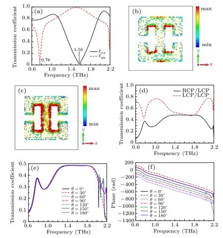
Fig. 2. Transmission characteristics and surface current distributions of the unit cell. (a) Transmission coefficients under a linear-polarized beam.(b)Surface current distributions caused by an x-polarized wave at 1.58 THz.(c) Surface current distributions caused by a y-polarized wave at 0.76 THz.(d) Transmission coefficients from LCP incidence when θ =0°. Transmission coefficients (e) and the phase (f) of cross-polarized waves under LCP incidence with varying rotation angles.
In order to further illustrate the forecasts of Eq. (3), we analyze the phase modifications of Ecross-poland Eco-poltransmitted waves, with different orientation angles of unit cells,and the consequences are shown in Fig. 3. For the Eco-poltransmitted component,the phase is always kept constant with varying rotating angles of unit cells. On the contrary, for the cross-pol transmitted component, the phase change shows a clear linear relationship and the value is twice as much as the rotation angle. These results respond to the theoretical analysis of Eq. (3). In other words, the expected local phase variation could be easy tailored using unit cells with different angles.
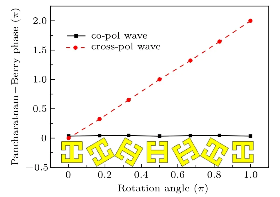
Fig.3. The phase variation of the Ecross-pol and Eco-pol transmitted components,as a function of the orientation angles of the unit cells,as well as the corresponding unit cells.
After finding the suitable unit cell, we now design the metasurfaces used with the unit cells. Metasurfaces with different topological charges of 1/2,1,3/2,2 and 5/2 are designed and the top views of metasurfaces are illustrated in Figs.1(a)and 4. Each metasurface includes two circular arrays. The radius of the inner ring is R1q=180 µm, and the outer ring is R2q=280 µm, q=1/2,1,3/2 and 2. In addition, q=5/2,R1q=280µm and R2q=380µm. The geometric dimensions of the unit cells are the same as the aforementioned single one,as shown in Fig.1(b).
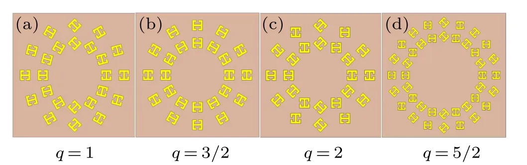
Fig.4.Spatial arrangement of unit cells of different VPPs with four different topological charges.
3. Results and discussion
The magnitude and phase distributions of crosspolarization transmission waves from the proposed VPPs are numerically investigated using CST Microwave Studio,where open boundaries in the x and y directions are applied. The circularly polarized(LCP and RCP)Gaussian beams are illuminated on the front of the metasurfaces, and a field monitor is set at Z=−800µm to record the transmitted electric field.The results are shown in Fig. 5. As shown in the figure, the emerging cross-polarization beams all appear as a dark spot at the origin, because of the phase singularity at the beam center, and the light intensity is distributed only on the ring.However, the amplitude distributions are not uniform probably because the arrangement is not very compact and even.Such defects could be improved by changing the number of unit cells in each ring and the number of rings on the metasurface.This is actually to reduce the interval of phase change.At the same time,the adjacent phase gradient of the metasurfaces increases, and the size of singular points also becomes more and more obvious as the topological charge increases. While comparing the phase profiles(b)and(d),it is observed that the phase changes by|l·2π|around the origin with both LCP and RCP incidence and the value is also equal to twice the topological charge of the metasurfaces, that is, l·2π =±2q·2π.However, changing the input polarization state from LCP to RCP does not change the magnitude profile, but reverses the twist directions of the phase profile. That is to say, the sign of the topological charge reverses, while the number of spirals remains unchanged. These results are consistent with the previous analysis,with the sign of l relying on the chirality of the incident wave. Furthermore, the twist direction of wavefronts is inverse using the same metasurface by transforming the handedness of the incident wave, implying that this unit cell possesses birefringent properties. In our work, the spinorbit interaction is the reason of production of OAM at the phase of the vortex beam.[4]Besides, this method could be used to generate THz vortex beams with higher topological charges.
As discussed in Eq.(3),the transmitted field has two components: the crosspolarization component energy is 25% of the total energy of incident,which is the theoretical limit value of the crosspolarization conversion efficiency of a single-layer metasurface,[31]while the remaining 25% energy maintains the polarization state of incident wave. For this part of energy, phase changes cannot be introduced, so there is no vortex characteristic. In our work, the conversion efficiency of the unit cell is around 23%, while the efficiency of VPPs we proposed are about 10%. Actually, although the arrangement of two concentric rings can generate vortex beams of any order easily and conveniently, the crosspolarization conversion efficiency will be reduced because this arrangement cannot make the unit structure covered with the whole metasurface.However, the efficiencies of the unit cells under different rotation angles are all 23% in the operational band. That is to say, we can generate vortex beams with a maximum conversion efficiency of 23% in the transmission field by arranging the unit cells we proposed reasonably. As mentioned in other literature, when the whole metasurface is fully filled by the unit cells,the conversion efficiency of the unit cell is approximately regarded as the efficiency of the vortex beam generated by the metasurfaces. Of course,we can increase the efficiency by increasing the number of concentric circles and the number of cells. Therefore,the unit cell proposed in our work can be used to generate vortex beams with a maximum conversion efficiency of 23%.

Fig. 5. Magnitude profiles and phase distributions of the THz vortex beam generated by the metasurfaces with distance to the metasurfaces of Z =−800µm at 1.6 THz. The magnitude profiles(a),(c)and the phase distributions(b),(d)of the cross-polarization component of the transmitted beams.The(a),(b)and(c),(d)rows correspond to LCP and RCP incident beams,respectively.

Fig. 6. (a), (b) Magnitude and phase distributions of the THz vortex beam at 1.6 THz with distance to the metasurfaces of Z =100 µm,−300µm,−500µm,−800µm,and −1000µm.
Figure 6 shows the magnitude and phase distributions of the converted transmitted vortex beam at 1.6 THz at different propagation distances. A phase singularity exists at the origin due to noncontinuous phase changes introduced by rotating the unit cells,which brings about the zero intensity at the core of the beam and retains at different propagation distances.The dark spot at the origin is bigger and appears in a divergent state at a propagation distance of 100µm(λ/2)of subwavelength.When the distance increases,the spot becomes convergent and the dark spot becomes larger with distance. However,the dark spots spread steadily throughout the process, which confirms that the vortex beam reserves in the cross-polarized wave and is stable in the propagation. Meanwhile,it is can be observed that the equiphase lines are the spoke-wise rays in the beginning, and with the increase of the propagation distance, they transform into the winding curves. Besides, the phase profile rotates in a clockwise direction when the beam propagates in the different propagation distances, as indicated in Fig. 6(b).These imply that the transmitted THz vortex beams have a high fidelity in the propagation process. The analytic expression of the Laguerre–Gaussian (LG) mode is analyzed to explain phase properties of the vortex field.[22]The LG modesare given by

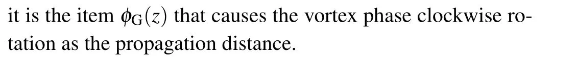
To analyze the broadband features of the designed metasurfaces,we take the metasurface of q=1/2 as an example to discuss. Figure 7 shows the magnitude and phase profiles of generated THz vortex waves at 800µm away from the metasurface, under different frequencies of 1.2 THz, 1.6 THz and 1.9 THz respectively. From the magnitude maps,it is discovered that the perfect doughnut shapes and unchanging dark spots are showed in all working frequency bands. We also note that the dimension of doughnut shapes is different on three incident frequencies, which could be caused by different interferences occurring in three frequencies. Furthermore,the phase profiles also show the helix outlines and all curve in a clockwise direction. Therefore,both the magnitude and the phase distributions hold a high fidelity to the vortex behavior in a broadband range. Based on the aforementioned discussion, we can judge that the ultra-thin transmission metasurfaces possess perfect characteristics in a wide working bandwidth.
Fig. 7. Magnitude and phase distributions of the THz vortex beam (l =1)under the LCP normally incident with different frequencies.
4. Conclusions
In summary,we design ultra-thin THz transmission metasurfaces with topological charge q by rotating the angle of the P-B phase elements. The metasurfaces are capable of generating THz vortex beams carrying integer magnitudes of OAM values ranging from ±1 to ±5. The numerical simulation results indicate that the designed metasurface possesses the cross-polarization conversion efficiency of 10% and a broad bandwidth of 0.7 THz in the frequency range of 1.2–1.9 THz.Besides,vortex beams with a maximum conversion efficiency of 23%in the transmission field could be generated by increasing the number of concentric circles and the number of cells on metasurfaces. The evolution properties of the generated THz vortex beam have also been investigated.The results show that the phase profile always rotates in a clockwise sense and the generated THz vortex beam has a high fidelity in the propagation process. The proposed method provides a novel way to design high-efficiency and broadband transmission vortex beam generators. The proposed metasurfaces can be widely applied to integrated optics and vortex optics.
杂志排行

Chinese Physics B的其它文章
- Corrosion behavior of high-level waste container materials Ti and Ti–Pd alloy under long-term gamma irradiation in Beishan groundwater*
- Degradation of β-Ga2O3 Schottky barrier diode under swift heavy ion irradiation*
- Influence of temperature and alloying elements on the threshold displacement energies in concentrated Ni–Fe–Cr alloys*
- Cathodic shift of onset potential on TiO2 nanorod arrays with significantly enhanced visible light photoactivity via nitrogen/cobalt co-implantation*
- Review on ionization and quenching mechanisms of Trichel pulse*
- Thermally induced band hybridization in bilayer-bilayer MoS2/WS2 heterostructure∗