Observation of trapped and passing runaway electrons by infrared camera in the EAST tokamak*
2021-05-24YongKuanZhang张永宽RuiJieZhou周瑞杰LiQunHu胡立群MeiWenChen陈美文YanChao晁燕JiaYuanZhang张家源andPanLi李磐
Yong-Kuan Zhang(张永宽), Rui-Jie Zhou(周瑞杰), Li-Qun Hu(胡立群),†, Mei-Wen Chen(陈美文),Yan Chao(晁燕), Jia-Yuan Zhang(张家源), and Pan Li(李磐)
1Institute of Plasma Physics,Hefei Institutes of Physical Science,Chinese Academy of Sciences,Hefei 230031,China
2University of Science and Technology of China,Hefei 230026,China
Keywords: tokamak,trapped runaway electron,synchrotron radiation
1. Introduction
If the electric field exceeds a critical value, a fraction of electrons,known as runaway electrons,can be detached from the bulk population and accelerated to relativistic energy.[1]In tokamaks, runaway electrons can be generated during disruption when a current quench induces a strong electric field in the toroidal direction, whilst the feedback control system also generates an electric field in the toroidal direction in order to maintain the plasma current(Ip).[2]Runaway electrons can also be generated during the current ramp-up or flat-top phase.In present-day tokamaks,the energy of runaway electrons can reach tens of MeV.The loss of such high-energy runaway electrons can cause severe damage to the plasma facing components in large scale tokamaks and in particular ITER.[3–5]
When the high-energy electrons are accelerated or forced to travel in a curved path by a magnetic field, synchrotron radiation is produced. The spectral power density of the synchrotron radiation emitted by relativistic electrons is well known and follows the equation[6]
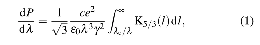
where γ is the Lorentz factor for runaway electrons,λc= 4πmecγ||/3γ2eB, meis the electron mass, γ||=(1−(v‖/c)2))−1/2, and K5/3is a modified Bessel function of the second kind.
Synchrotron radiation is a powerful tool to infer the parameters of high energy runaway electrons, and the radiation diagnostic system can provide direct images of the distribution of the runaway electrons inside the plasma.[7]
In EAST, the synchrotron radiation emitted by runaway electrons is mostly infrared[8,9]It is much easier to observe synchrotron radiation images with an infrared camera than with a visible camera.The synchrotron radiations of almost all shots can be observed by infrared camera,while visible camera can observe the radiations only when the runaway electron radiation is very strong.
The runaway electrons emit synchrotron radiation predominantly along the electron’s velocity vector,with a γ−1angle spread. Since the energy of runaway electron is typically tens of MeV,the direction of emission can be approximated as a straight line along the electron’s velocity vector.[10]Hence,the synchrotron radiation is emitted mainly in the opposite direction of Ipand radiation images can be observed only by a camera pointing in the Ipdirection.
In tokamaks, the synchrotron radiation of passing runaway electrons during the current ramp-up phase can be easily observed. Although it is not very difficult to observe the trapped runaway electrons in EAST, it is generally believed that the fraction of trapped runway electrons is so small that they are disregarded,and no one pays attention to the trapped runaway electrons. To the best of our knowledge, this is the first time that the synchrotron radiation from trapped runaway electrons has dominated that from runaway passing electrons and has been identifiable in an image. From the numerical simulation perspective, with the exception of Ref. [11], most of studies have focused on synchrotron radiation by passing particles in axisymmetric magnetic fields.
As for the generation of these trapped runaway electrons in EAST,it has not been studied clearly,but here are a few conjectures about the origin of trapped runaway electrons. Reference[12]indicates that trapped electrons cannot gain MeV energy directly from the inductive electric field. The pitch angle scattering due to high-Z impurities can give rise to the runaway electrons with large pitch angle,which may make them trapped. At present, trapped runaway electrons appear only during the current ramp-up and early flat-top phase,the plasma temperature is relatively low,and there are more partially ionized impurities. The reduced-screening effect of bound electrons can enhance pitch-angle scattering,[13]which may lead to a higher proportion of trapped runaway electrons in this phase. With the increase of plasma temperature, the impurities lose more electrons and even ionize completely,this effect is weakened, and the trapped runaway electrons are reduced so that they cannot be observed from the camera. In addition,Multiple knock-on collisions and the whistler waves may also make them trapped.[14]
The rest of the paper is organized as follows.In Section 2,the synchrotron radiation of passing runaway electrons is discussed. In Section 3,the main experimental observation of infrared emission of trapped runaway electrons is implemented in EAST,along with an analysis inferring the energy and pitch angle(the angle between the trajectory of the runaway electron and the magnetic line of force)of the electrons from the data through using a simplified test particle model. And in Section 4 the conclusions are drawn from the present study.
2. Passing runaway electron synchrotron radiation images
Synchrotron radiation images of passing runaway electrons have been observed in many tokamaks, such as EAST,[15]KSTAR,[16–18]C-Mod,[2]and DIII-D.[19–22]The position and orientation of the infrared camera on EAST are described in Ref. [9]. The synchrotron radiation images of passing runaway electrons observed in these devices are generally consistent with the theoretical prediction of Pankratov in Ref. [23]. In Ref. [10], simulations were performed based on the theory of Pankratov, the results of which are in good agreement with the experiments. The synchrotron radiation intensity simulations presented in this section are also based on Ref. [10]. The variations of the radiation intensity at different positions are caused mainly by the variation of magnetic field and pitch angle.It is assumed that the magnetic field is inversely proportional to the major radius R,and the pitch angles at different values of R are calculated under the assumption of the conservation of magnetic moment µ =mv2⊥/2B. As discussed in Ref.[10],the synchrotron radiation of runaway electron cannot be observed in some regions. However,the larger the pitch angle, the larger the observable area is. Most of the runaway electrons observed in EAST are within r=35 cm. It is assumed that the radius reof the runaway electron beam is 35 cm. When the pitch angle is greater than 0.24 radians, the synchrotron radiation images can be completely observed by infrared cameras in the EAST.According to the intensity of synchrotron radiation and the pitch angle,the shape of synchrotron radiation can be classified as three categories.Since the reduced radial transport happens near the low-order rational surfaces, the runaway electron beams tend to gather here to form a ring structure.[17,24]Only in very few discharge cases,may the runaway electrons be uniform distribution. So,six types of synchrotron radiation images can be observed by infrared cameras as shown in Table 1. In Table 1, the uniform distribution means that the density distribution of runaway electrons is uniform in a range of r <35 cm. The nonuniform distribution means that there are no runaway electrons when r <20, and there are runaway electrons in a range of 20 cm <r <35 cm. In order to make the simulation simple,the density distribution in the range of 20 cm<r <35 cm is set to be uniform. When the intensity of synchrotron radiation is weak,the synchrotron radiation on the low field side cannot be observed,so the two types of synchrotron radiations,of which pitch angle is greater and less than 0.24 rad,are the same. To simulate this situation, an appropriate value from the simulation in Fig. 1 or Fig. 3 is subtracted, and the value less than zero is changed into zero. Therefore,the eight pictures in Table 1 belong in six different types. In the following,there are presented the detailed analyses of the six types of synchrotron radiation images.

Table 1. Six types of synchrotron radiation images.
Firstly,the case of strong synchrotron radiation and pitch angle greater than 0.24 rad is investigated. In this case, the synchrotron radiation images can be completely observed by infrared cameras. Generally, the runaway electrons are concentrated near a magnetic surface. Based on Pankratov’s theory, two types of runaway electron synchrotron radiation images can be observed as shown in Fig.1. Previously,only the type in Fig.1(b)was observed in EAST.An example is shown in Fig.2.

Fig. 1. Results of synchrotron radiation spot shape for runaway electrons with E=30 MeV,θp=0.35 rad,and q=2,showing that runaway electrons are concentrated in(a)r in range[20,35]cm and(b)r in[0,35]cm.
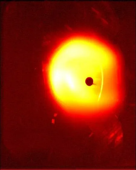
Fig.2. Synchrotron radiation image observed in EAST,belonging in type of Fig.1(b).
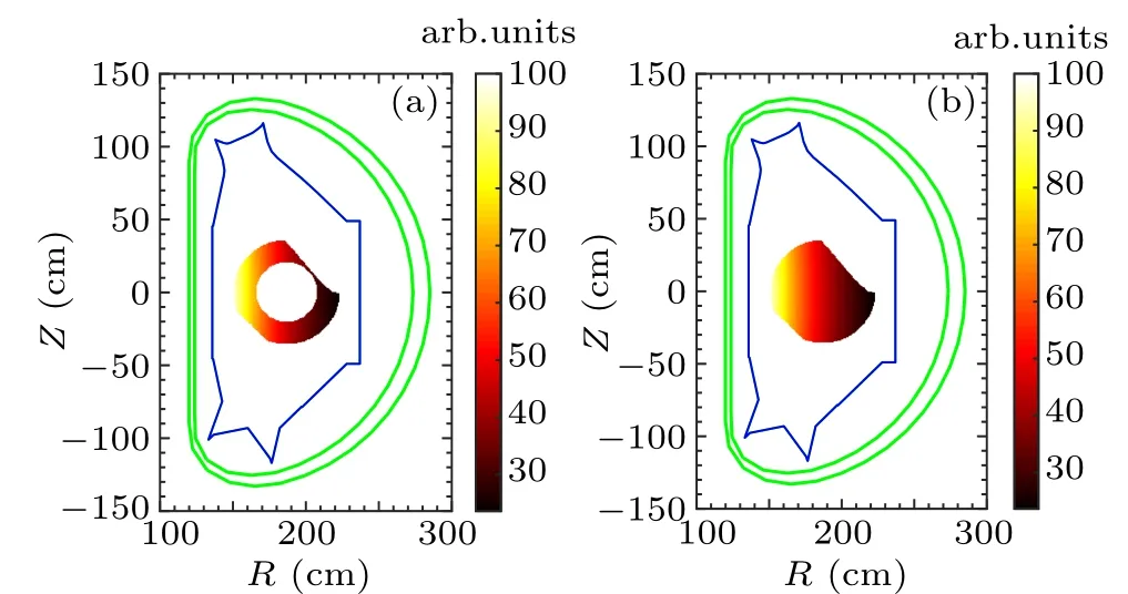
Fig. 3. Synchrotron images from simulations with E = 30 MeV, θp =0.18 rad, and q=2, showing that runaway electrons are concentrated in(a)r in range[20,35]cm and(b)r in[0,35]cm.
The most common synchrotron radiation images observed in EAST indicate that runaway electrons typically have small pitch angles. When it is the case,the synchrotron radiation cannot be observed in some areas. Figures 3 and 4 show the simulation results and runaway electron radiation images observed by infrared camera,respectively. The simulation results are in good consistence with the shapes of the runaway electron synchrotron radiation observed by the camera.[2]
It can also happen that the synchrotron radiation on the low field side is too weak to be observed by the infrared camera as shown in Figs.5 and 6. In this case,the results are the same no matter whether the pitch angle is greater than 0.24 rad.
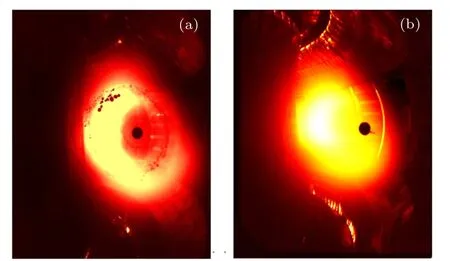
Fig. 4. Synchrotron radiation images observed in EAST, where types of panels(a)and(b)correspond to those of panels(a)and(b)in Fig.3,respectively.
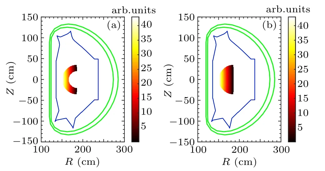
Fig. 5. Results of synchrotron radiation spot shape for runaway electrons with E =30 MeV and q=2, showing that runaway electrons are concentrated in (a) r in range [20, 35] cm and (b) r in [0, 35] cm. Synchrotron radiation on low field side is too weak to be observed.
In EAST, the synchrotron radiation shapes of Figs. 4(a)and 6(a) are the two most common types. When the runaway electron synchrotron radiation just appears or is about to disappear,since the synchrotron radiation intensity is weak,most of the synchrotron radiation images belong in the type in Fig. 6(a). However, when the runaway electron synchrotron radiation is relatively strong, the type in Fig.4(a)is the most common.
Among the above categories of the synchrotron radiation dominated by passing runaway electrons, the intensity of the synchrotron radiation decreases gradually from the high-field side to the low-field side,because the intensity of the magnetic field and pitch angle decrease gradually from the high-field side to the low-field side.
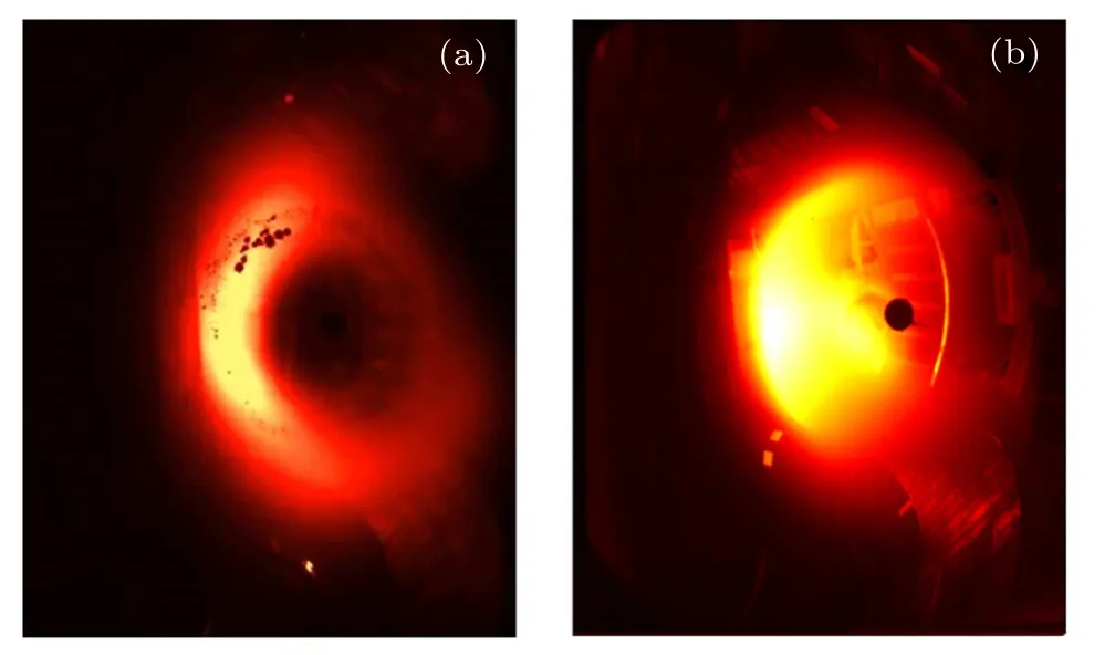
Fig.6. Synchrotron radiation image observed in EAST,where types of panels(a)and(b)correspond to those of panels(a)and(b)in Fig.5,respectively.
3. Trapped runaway electron synchrotron radiation images
In the previous section, the synchrotron radiation from passing runaway electrons is analyzed. This section focuses on the first experimental observation of the synchrotron radiation by trapped runaway electrons. In this case, the emission on the high-field side is weaker, because the deeply trapped electrons cannot reach the high-field side. The synchrotron radiation, which is dominated by trapped runaway electrons, is not difficult to be observed. Here we analyze the most obvious and clearest one in EAST.The trapped runaway electrons are observed with an infrared camera as shown in Fig.7. The observed radiation pattern exhibits bright spots located at the tips of the banana orbits consistent with the synchrotron radiation images of trapped runaway electrons with initial parameters of E=10 MeV and θp=60°in DIII-D in Ref.[11].

Fig.7. Synchrotron radiation image of trapped runaway electrons observed by infrared camera at 1.3 s. Synchrotron radiation of trapped runaway electrons forms bright spots marked here by two black circles.
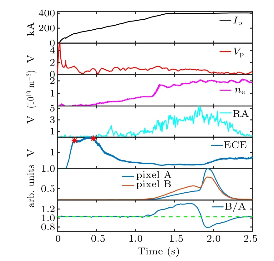
Fig. 8. Time slice of runaway discharge in EAST shot 80948. Waveforms are plasma current,loop voltage,line-averaged density,raways(RA)signal is thick-target bremsstrahlung hard x-rays produced by runaway electrons hitting the first wall, electron cyclotron emission, synchrotron radiation intensity at pixels A and B,ratio of synchrotron radiation intensity at pixel B to that at pixel A.
In Fig. 7, the position with the strongest trapped runaway electron radiation(labeled pixel B)and the position with the strongest passing runaway radiation (labeled pixel A) are marked. The ratio of the synchrotron radiation intensity at pixel B to that at pixel A in shot 80948 is given in Fig. 8.It can be seen that in the interval of 1.25 s–1.84 s, the intensity at pixel B is stronger than that at pixel A. That is to say,the synchrotron radiation of the trapped runaway electrons is dominant during the interval of 1.25 s–1.84 s.
3.1. Energy of runaway electrons
There are several ways to estimate the energy of runaway electrons.
Here we use two methods. The first method is based on the energy dependence of the shift, δ,of the drift orbit,[25,26]which satisfies the relation δ = qγmec/eB. So the energy of the runaway electron is E =δecB/q.[9]According to the geometry of Fig. 9, we estimate the average shift at 〈δ〉 =5.56 cm. Then, assuming the beam to be located around the q=4 rational surface, the mean energy of the runaway electrons can be roughly estimated at 8 MeV at 1.55 s.

Fig.9. One frame of images obtained by infrared camera at 1.55 s,with δ denoting distance of runaway electrons drift orbit from magnetic surface.
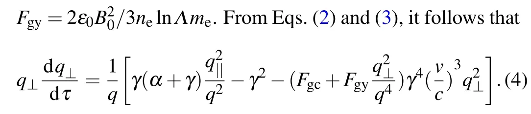
The second method to estimate the energy is based on the dynamics of relativistic electrons in a tokamak described with the test particle equations[27,28]

In this shot, the electron cyclotron emission (ECE) signal is always strong in the interval 0.22 s–0.46 s,i.e.,between the two red symbols (*) in Fig. 8. In this period, the ECE signals come mainly from fast electrons, which means that there are adequate fast seed electrons at 0.22 s. The initial energy of 220 keV is given to the runaway electrons at 0.22 s,in which the energy in the direction parallel to the magnetic field is 197 keV and the energy in the direction perpendicular to the magnetic field is 23 keV.Based on this initial energy,the energy evolution of runaway electrons can be calculated from Eqs.(3)and(4). As shown in Fig.10,the resulting energy of the runaway electrons is 13.5 MeV at 1.3 s and 14.7 MeV at 1.55 s. In this method. only the influence of the collision on the lateral velocity component of the runaway electron is taken into consideration,so the pitch angle of the runaway electron will be underestimated. Because the synchrotron radiation of runaway electrons is sensitive to the pitch angle, this method overestimates the energy of the runaway electrons. According to the energy calculated by these two methods,we can roughly estimate the energy of the runaway electrons at about 10 MeV in the interval from t=1.3 s to t=1.55 s.
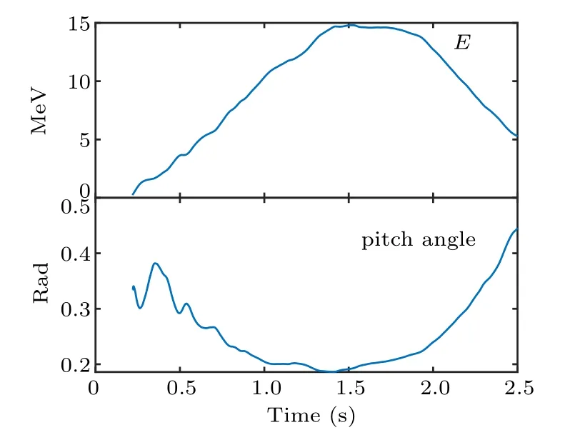
Fig.10. Energy and pitch angle evolution of runaway electrons,calculated from Eqs.(3)and(4).
3.2. Pitch angle of runaway electron
Based on the energy obtained above, the pitch angle of the runaway electron can be estimated from the synchrotron radiation intensity. Figure 11 shows the normalized radiation intensity at 1.3 s, where the intensity at pixel B is about 0.95 and the intensity at pixel C(blue dot)is about 0.56. There is no reflection on the wall in the blue ellipse in the figure, and there is almost no synchrotron radiation of the runaway electrons. Therefore, we take the average of 0.51 in the ellipse as background thermal radiation. Then the synchrotron radiation intensities of the trapped runaway electrons at pixel B and pixel C are 0.44 and 0.05, respectively. At the tips of the banana orbit, the guiding center velocity of the trapped runaway electrons is much slower than that at other locations,causing the trapped runaway electrons to turn dense here. It is roughly assumed that the density of trapped runaway electrons is inversely proportional to the guiding center velocity. Since magnetic momentµ =mv2⊥/2B is constant,the pitch angle at pixel B and pixel C are related. The synchrotron radiation intensity of runaway electrons can be calculated from Eq. (1).The energy of trapped runaway electron is 10 MeV, and the magnetic field at pixel B(R=1.6 m)and pixel C(R=1.85 m)are 2.3 T and 2.0 T respectively. Taking into account the variation of the density and pitch angle of the runaway electrons,and the magnetic fields at different positions,when pitch angle is about 1.47 rad at pixel B,the ratio of the radiation intensity of pixel B to that of pixel C is consistent with the experimental value. Therefore,the pitch angle of runaway electrons can be estimated at 1.47 rad at pixel B,and 1.18 rad at pixel C.

Fig.11. Image of normalized synchrotron radiation intensity at 1.3 s,which is 0.95 at pixel B.
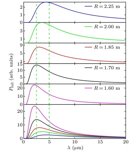
Fig. 12. Synchrotron radiation spectra in EAST with E =10 MeV at several R positions, where pitch angles corresponding to these R positions are 1.47 rad,1.31 rad,1.18 rad,1.10 rad,and 1.00 rad respectively,and infrared range for infrared camera(2.5µm–5µm)is marked with green dashed lines.
According to the previous results, we can obtain the trapped runaway electron (single-particle) synchrotron radiation spectra at several R positions as shown in Fig.12. We can also obtain the trapped runaway electrons synchrotron radiation intensity(in the wavelength range of the infrared camera)at several R positions as shown in Fig. 13. In this figure, the radiation intensity is normalized,and the background thermal radiation is set to be 1. The blue columns are the calculated results,and the red columns are the measured results. The calculation results denoted by the red and yellow dots(in Fig.11)are consistent with the measurement results, so it proves that the pitch angle of pixel B is 1.47 rad,which is reliable.
3.3. Relative density of trapped runaway electrons
The runaway electron synchrotron radiation is very sensitive to the pitch angle. Although the trapped runaway electron synchrotron radiation is dominant,the relative number of trapped runaway electrons may not be large. Here is a rough calculation of the relative number of trapped runaway electrons at 1.3 s.

Fig. 13. Intensities of trapped runaway electrons synchrotron radiation in wavelength range of 2.5µm–5µm at several R positions.
After deducting the background radiation intensity at 1.3 s, the radiation intensity of pixel B is 2.1 times that of pixel A. Here we analyze the runaway electron at 1.3 s. It is assumed that the pitch angle of the passing runaway electron is roughly 0.15 rad.[9]According to the conservation of magnetic moment and the relationship between magnetic field B and R. We can calculate that the pitch angle of passing runaway electrons at pixel A is about 0.17 rad and at pixel B is about 0.16 rad.
Assuming that the energy of passing runaway electrons is the same as that of trapped runaway electrons, specifically,they are both 10 MeV. The single-particle synchrotron radiation spectra of trapped and passing runaway electrons are shown in Fig.14. In the band that the camera can observe,the radiation intensity of the trapped runaway electrons is much greater than that of the passing runaway electrons. In order to satisfy that the radiation intensity at pixel B is 2.1 times the radiation intensity at pixel A in the 2.5 µm–5 µm band, the passing runaway electron density at pixel A needs to be 14608 times the density of the trapped runaway electrons at pixel B.
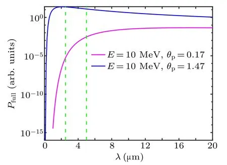
Fig.14.Single-particle synchrotron radiation spectra of trapped and passing runaway electrons,where infrared range for infrared camera(2.5µm–5µm)is marked with green dashed lines.
The synchrotron radiation damping of passing runaway electrons is weaker and they can be well accelerated by the electric field. So the energy of the passing runaway electrons is usually higher than that of trapped runaway electrons. Here it is assumed that the energy of the passing runaway electrons is 15 MeV, then the density of passing runaway electrons is 128 times the density of trapped runaway electrons.Assuming that the trapped runaway electron energy can reach 20 MeV,then the density of passing runaway electrons is 21 times the density of trapped runaway electrons. No matter which one of the previous assumptions is adopted,the density of trapped runaway electrons is much smaller than that of passing runaway electrons. The runaway electron synchrotron radiation is very sensitive to the pitch angle. Although the energy and density of trapped runaway electrons are low,it can dominate synchrotron radiation.
4. Summary
In this paper, the infrared synchrotron radiation of runaway electrons in EAST is analyzed in detail. The most common is the synchrotron radiation pattern dominated by passing runaway electrons. However, sometimes, synchrotron radiation dominated by trapped runaway electrons can also be observed. This is the first time that the synchrotron radiation from trapped electrons has dominated that from passing electrons and is identifiable in an image.
According to the intensity of synchrotron radiation and the pitch angle of passing runaway electrons,the shape of synchrotron radiation can be divided into three categories. The larger the pitch angle,the larger the observable area is. When the pitch angle is greater than a certain value and the synchrotron radiation is sufficiently strong,the synchrotron radiation images can be completely observed by the infrared camera in EAST.The synchrotron radiation images dominated by passing particles all have one thing in common: the radiation intensity gradually decreases from the high- to the low-field side. Hence,when the runaway electron synchrotron radiation is weak, the emission on the low-field side is almost undetectable,only the emission on the high field can be observed.
In EAST,the trapped runaway electrons can dominate the radiation synchrotron. In this case,the radiation intensity does not decrease from the high- to the low-field side. Since the deeply trapped runaway electrons cannot reach the high-field side,the radiation on the high-field side is weak. In addition,the trapped runaway electrons cannot be continuously accelerated by the electric field and the synchrotron radiation damping of trapped runaway electrons is stronger. Therefore, the energy of trapped runaway electrons is low,and it cannot reach tens of MeV like the passing runaway electrons.In shot 80948,the energy of trapped runaway electrons is only about 10 MeV with a pitch angle about 1.18 rad(67°)at R=1.85 m.
In the theoretical and experimental studies of runaway electrons, it is generally believed that the runaway electrons have a small pitch angle, close to zero when the electric field is high.[2,10,28,29]In this experiment,the synchrotron radiation images of the trapped runaway electrons are observed during the current ramp-up phase under a high electric field. The trapped runaway electron images show that in this case there is a small number of runaway electrons whose pitch angle is large enough to be trapped. Runaway electron synchrotron radiation is very sensitive to the pitch angle. Although the proportion of trapped runaway electrons is low, it can dominate the synchrotron radiation. The theoretical research does not ascertain the emergence of trapped runaway electrons very clearly, but from the current experimental phenomena, the pitch angle scattering due to high-Z impurities and knock-on collision should contribute a lot to the trapped runaway electrons.
杂志排行

Chinese Physics B的其它文章
- Corrosion behavior of high-level waste container materials Ti and Ti–Pd alloy under long-term gamma irradiation in Beishan groundwater*
- Degradation of β-Ga2O3 Schottky barrier diode under swift heavy ion irradiation*
- Influence of temperature and alloying elements on the threshold displacement energies in concentrated Ni–Fe–Cr alloys*
- Cathodic shift of onset potential on TiO2 nanorod arrays with significantly enhanced visible light photoactivity via nitrogen/cobalt co-implantation*
- Review on ionization and quenching mechanisms of Trichel pulse*
- Thermally induced band hybridization in bilayer-bilayer MoS2/WS2 heterostructure∗