Improved nonlinear parabolized stability equations approach for hypersonic boundary layers*
2021-05-24ShaoxianMa马绍贤YiDuan段毅ZhangfengHuang黄章峰andShiyongYao姚世勇
Shaoxian Ma(马绍贤), Yi Duan(段毅), Zhangfeng Huang(黄章峰),†, and Shiyong Yao(姚世勇)
1Department of Mechanics,Tianjin University,Tianjin 300072,China
2Science and Technology on Space Physics Laboratory,China Academy of Launch Vehicle Technology,Beijing 100076,China
Keywords: nonlinear parabolized stability equations (NPSEs), hypersonic boundary layers, streamwise wavenumber
1. Introduction
Transition prediction is a significant aspect of the design of hypersonic vehicles, and is relevant to the thermal protection,load capacity,and stability of these aircraft. The theoretical basis of natural transition prediction is the linear stability theory (LST).[1]It is appropriate for parallel flow, but nowadays,to take account of both nonparallelism and nonlinearity of shear flows, the nonlinear parabolized stability equations(NPSEs) approach[2]has become popular, and it is definitely more efficient than direct numerical simulation(DNS).[3]
In traditional stability theory,a perturbation is introduced into the mean flow as follows: Q(x,y,z,t) = Q0(x,y,z)+Q′(x,y,z,t),where x,y,and z are the streamwise,normal,and spanwise coordinates,respectively,and t is time.Because both the instantaneous flow Q and mean flow Q0separately satisfy the Navier–Stokes (N-S) equations, one can easily obtain the governing equations of the perturbation Q′.The basic idea behind the NPSEs approach is that the perturbation consists of a series of disturbance waves as follows:where the matrices Amnand Bmnare functions of the mean flow Q0and the streamwise wavenumber αmnand they can be found elsewhere.[4]


Because there are two unknown variables ˇqmnand α(m,n) in Eq. (3), an additional iteration rule for α(m,n) is required to solve this problem. For compressible flow,the following iteration method is generally applied:

Owing to its advantages,[2]the NPSEs approach has proved to be a powerful tool for the study of boundary layer stability and for prediction of transition location. Herbert[5]and Bertolotti and Herbert[6]applied the parabolized stability equations to the incompressible and compressible boundary layers, respectively. Bertolotti et al.[7]and Esfahanian et al.[8]applied the NPSEs method to the Blasius boundary layer and found that the results obtained for both the amplitudes and eigenfunctions of disturbances were consistent with the results of DNS.Subsequently,supersonic plate boundary layers were investigated by Chang et al.[9]and Zhang and Zhou.[10–12]Recently, Paredes et al. studied the hypersonic boundary layer over a flat plate[13]or a blunt cone.[14]In addition to the plate boundary layer, crossflow instability of a three-dimensional boundary layer is a common cause of transition in sweptwing flows. Malik et al.[15]and Haynes and Reed[16]used the NPSEs to simulate the evolution of stationary crossflow vortices on a 45°swept NLF(2)-0415 airfoil. They obtained the results for the nonlinear evolution of the stationary crossflow vortex and the influence of roughness elements on the transition position that were in good agreement with the earlier experimental results of Reibert et al.[17]Xu et al.[18]studied the single unstable crossflow mode in a compressible swept-wing boundary layer and obtained a relationship between the Mach number and saturation amplitude. Recently, Sousa et al.[19]and Chynoweth et al.[20]simulated a Mach 6 flared cone in the Boeing/U.S.Air Force Office of Scientific Research Mach-6 Quiet Tunnel. The results from the NPSEs approach were consistent with those from DNS and from experimental studies.Chen et al.[21]simulated the nonlinear interaction between the high-frequency second mode and the low-frequency modes in a Mach 6 flared cone boundary layer using the NPSEs.
However,the NPSEs approach has its own shortcomings.Because it takes the history of the disturbance into account,[2]the growth rate depends both on the history of the mean flow and on the initial conditions. It has the property of weak ellipticity, which imposes a limit on the smallest permissible size of the marching step. Its streamwise wavenumbers for high harmonics are not self-consistent.[22]It is difficult to extend the NPSEs to three-dimensional (3D) boundary layers where the spanwise wavenumber varies along the marching line. Fortunately,there are ways to overcome these shortcomings. Huang and Wu[23]proposed a nonperturbative approach that provided an accurate initial condition for NPSEs by taking nonparallelism into account. Zhang and Su[22]suggested that the streamwise wavenumber be kept real to ensure selfconsistency of the NPSEs. Song et al.[24]applied ray tracing theory to predict the real part of the spanwise wavenumber and determined its imaginary part using the conservation relation for the generalized growth rate[25]for 3D boundary layers.
NPSEs were originally derived for incompressible flow,but can easily be extended to supersonic flow with small Mach numbers. As shown in Fig. 1(a), there is only one unstable mode in supersonic flow on a flat plate with Mach number 2.25. Usually, the most-unstable waves, such as (1,1) and(1,0),are imposed at the inlet,and they always play a leading role. Owing to the nonlinear effect, other harmonics are excited. Although some of these are stable and therefore can be ignored,others are unstable and their evolution must be taken into account.
However,there are some new problems in the application of the NPSEs to supersonic flow with a large Mach number or to hypersonic flow, where there are at least two unstable modes. As shown in Fig. 1(b), the frequency of the mostunstable second mode in hypersonic flow on a flat plate with Mach number 6 is much larger than that of the first mode,leading to high calculational cost and poor efficiency, with most of the harmonics being unimportant because of attenuation.Zhang and Luo[26]expanded the traditional NPSEs into a transformed spectral space and were thereby able to efficiently simulate nonlinear interaction of two modes with arbitrary frequencies. For hypersonic flow on a swept blunt plate with an adiabatic wall,as shown in Fig.1(c),the occurrence of crossflow means that crossflow instability plays a dominant role. A stationary wave with large growth rate quickly reaches its saturation state, and its nonlinear interaction leads to large amplitudes of both harmonics and mean flow correction, which can easily cause divergence.[27]Zhao et al.[4]improved the traditional NPSEs by calculating the mean flow distortion in the linear operator instead of the nonlinear terms and by introducing an under-relaxation factor to compute the nonlinear terms. This improvement was validated by DNS and it was found that divergence was delayed. Furthermore, divergence can also occur in the process of modal transformation when the disturbances imposed at the inlet no longer play a leading role. As shown in Fig. 1(d), for hypersonic flow on a swept blunt plate with an isothermal wall, the effect of the cooling wall makes the second-mode instability wave more unstable but stabilizes the first-mode wave.[28]When two of the secondmode instability waves with the same frequency are added at the inlet, their nonlinear interaction excites stationary waves.Because the growth rate of the latter is much larger than that of the former, the latter quickly comes to play a leading role,leading to the occurrence of modal transformation. In the process of modal transformation,it is difficult to correctly obtain the streamwise wavenumber of some waves by the iteration method in Eq.(4),which leads to divergence of the traditional NPSEs.

Fig. 1. Growth rate contours in different cases: (a) supersonic flat-plate boundary layer(Ma=2.25);(b)hypersonic flat-plate boundary layer(Ma=6); (c) hypersonic swept-blunt-plate boundary layer with adiabatic wall(Ma=6,sweep angle 45°);(d)hypersonic swept-blunt-plate boundary layer with isothermal wall (Ma=6, sweep angle 45°, wall temperature 300 K).The waves imposed at the inlet are indicated by squares,the excited unstable waves by circles,and the excited decaying waves by crosses.
In this paper,the problem of divergence of the NPSEs is addressed and two major improvements are proposed to improve the robustness of the NPSEs approach. DNS is performed to verify and validate the predictions of the improved NPSEs in a hypersonic boundary layer on an isothermal swept blunt plate.
The rest of the paper is organized as follows. In Section 2, we present the improvements to the NPSEs. In Section 3,we introduce our numerical methods and the parameters we adopt. The results from the improved NPSEs are compared with those of DNS in Section 4. Finally,the work is summarized in Section 5.
2. Methodology
2.1. Definitions of dominant and non-dominant waves
All disturbances are divided into two types according to their importance: dominant waves and non-dominant waves.
1. Dominant waves occur in two circumstances:
(a) They can be imposed at the inlet, where they play a leading role, since the amplitudes of other waves are zero there.
(b) During the evolution of these imposed waves, owing to the nonlinear effect, all harmonics are excited, some of which have a large growth rate, with amplitudes that increase rapidly and can even exceed the amplitude of the imposed dominant waves. These harmonics thus play a leading role at this time and can therefore be considered as dominant waves.
2. Other harmonics are small, making very little contribution to the nonlinear effect, and these are defined as nondominant waves.

2.2. Calculation method for the streamwise wavenumber
The purpose of classifying disturbances is to enable calculation of streamwise wavenumbers using different methods for different types of wave. In most situations, the streamwise wavenumber can be obtained using the iterative method based on Eq.(4),especially when the waves imposed at the inlet always play a leading role,and this has been confirmed by many studies using the NPSEs approach. Because the dominant waves dominate throughout the evolution of disturbances,their streamwise wavenumbers ˜αmncan be calculated using Eq.(4).
For non-dominant waves, when the nonlinear effect is very strong or some of the excited waves begin to dominate, the disturbance energies ˇEmnof these higher harmonics[Eq.(5)]are very small,and some are particularly sensitive to the nonlinear interaction between the imposed waves, which makes it difficult for the iteration to converge and will eventually lead to divergence. In this paper, an alternative method,called the phase-locked method, is proposed to calculate the streamwise wavenumber for the non-dominant waves with the aim of overcoming the problem of divergence.
The basic idea comes from the so-called phase-locked phenomenon,[29,30]in which some waves that are related in some way travel with nearly the same phase speed. For example, if there is a fundamental wave with frequency ω11and wavenumber α11, then nonlinear interactions will lead to the generation of higher harmonics,including terms with frequency 2ω11and wavenumber 2α11,which will have the same phase speed c ≡ω/α=ω11/α11.Generally,a dominant wave(˜m,˜n) can excite a series of harmonics belonging to the nondominant wave(ˆm,ˆn),the wavenumbers will,according to the phase-locked phenomenon,satisfy

where k >1 is the order of a harmonic. The phase-locked phenomenon provides a satisfactory representation of the relationship between the real parts of streamwise wavenumbers,but it does not hold for their imaginary parts,and this is manifested as a lack of self-consistency.[22]Therefore, we adopt the suggestion of Zhang and Su[22]and set the imaginary part of the streamwise wavenumber(indicated by subscript i)equal to zero

The growth or attenuation characteristics of nondominant waves are then manifested in the modulus of their shape functions.
According to the NPSEs approach,most of the harmonics are excited mainly by the imposed waves owing to the nonlinear effect. If two fundamental waves (1,0) and (0,1) are imposed at the inlet, they can excite all harmonics(m,n)and determine their streamwise wavenumbers α(m,n). However,in some studies,these two fundamental waves are not imposed at the inlet,and instead two reference wavenumbers are introduced in the phase-locked method to calculate the real parts(indicated by subscript r) of the streamwise wavenumbers of the non-dominant waves as follows:

where kmand knare the reference wavenumbers of the reference waves(1,0)and(0,1),respectively.
The main problem now is how to determine the two reference wavenumbers kmand kn. Obviously, they should be calculated using the dominant waves. There are three typical calculation circumstances:

where p is a weighted power exponent,which we select p=1 in this paper. A comparison of weighted power exponents can be found in Appendix B.In particular,if there are only dominant waves with zero frequency,only harmonics with zero frequency can be excited,and so Eq.(15)degenerates to km=0.
In addition, as in the NPSEs of Zhao et al.,[4]we move the mean flow distortion into the linear operator and add an under-relaxation factor δ,which is chosen as 0.2.
3. Numerical methods and parameters
3.1. Physical model
The physical model considered in this work is a swept blunt plate. The blunt-plate model that we adopt has a nose radius r0=35 mm and a sweep angle ϕ =45°and is at a 0°angle of attack,as shown in Fig.2.
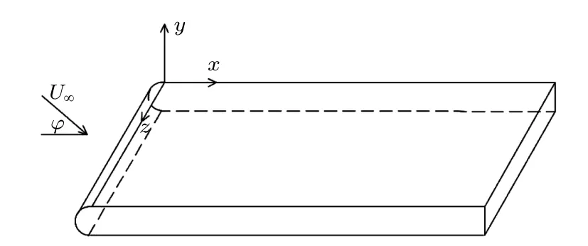
Fig.2. Sketch of the swept-blunt-plate model.
The conditions for the basic state calculation are a freestream Mach number Ma ≡U∞/c∞=6, a Reynolds number based on nose radius Re ≡ρ∞U∞r0/µ∞=79100, and a freestream temperature T∞=226.5 K.The thermal wall condition is isothermal,with a constant wall temperature Tw=300 K.
3.2. Direct numerical simulation
The mean flow and evolution of disturbances are also computed using a high-order DNS solver. A detailed description of the governing equations and their numerical solution was given by Song et al.[24,31]The convective terms from the governing equations are computed using a Lax–Friedrichs flux splitting method for the mean flow and a Steger–Warming flux splitting method for the evolution of disturbances,and they are discretized using a fifth-order weighted essentially nonoscillatory scheme. The viscous fluxes are discretized using a sixthorder central difference scheme, and time integration is performed using a second-order Runge–Kutta scheme. An inhouse code for DNS is used,which has been validated by Song et al.[24,31]and Zhao et al.[4,32]
Because the blunt plate is semi-infinite in the x direction and infinite in the z direction, only the upper half of a twodimensional(2D)blunt plate is selected to simulate the mean flow. Its dimensionless length in the x direction is Lx=200,and the height of the normal boundary gradually increases along the x direction and it is always above the shock layer.At the wall, no-slip and isothermal boundary conditions are used. A symmetric boundary condition is used on the symmetry line,and a free-stream condition is applied at the upper boundary. The grid size used in the calculation of the basic state contains 1601 points along the streamwise direction and 351 wall-normal, where 120 points in the boundary layer to satisfy the requirements near the nose,wall,and shock layer.
For simulation of the evolution of disturbances,only part of the computational domain of the 2D mean flow is used.Part of the domain in the x direction is selected, and the upper boundary of the computational domain is chosen to exclude the shock layer and thus allow the use of high-order finite difference schemes. The selected 2D mean flow is extended to 3D mean flow,and its dimensionless length in the z direction is Lz=2π/β0. A periodic condition is applied in the z direction,the inflow condition is determined by disturbances calculated using an LST analysis, and a far-field condition is applied at the upper boundary. Other boundary conditions are consistent with 2D DNS. The computational grid is based on the grid used for the NPSEs calculations with Ny=201 points in the wall-normal direction,which ensures that there are more than 120 points inside the boundary layer,the number of points in the x direction is increased so that there are a minimum of 30 points per streamwise wavelength of the fundamental wave,which results in a maximum of Nx=3001 points, and there are Nz=257 points distributed uniformly in the z direction.The total number of grid points for DNS of disturbance evolution is up to 150 million.
A convergence study for both the mean flow and the disturbance evolution by DNS has been performed by doubling the grid number in each direction separately, and the results are in good agreement with each other.
3.3. Linear stability theory
In this subsection,we present the LST results for the hypersonic boundary layer on a swept blunt plate. An isothermal condition is used at the wall. The neutral curves of different modes are displayed in Fig. 3. The dimensionless frequency ω =1 corresponds to a dimensional frequency f =8.2 kHz. The unstable crossflow-mode and second-mode frequency bands are clearly distinguishable,since they are separated by a stable region. The isothermal temperature imposed at the wall is 300 K, which is far less than the temperature on the adiabatic wall,leading to enhancement of second-mode instability.[33]On the one hand,the unstable range of the second mode is larger than that of the crossflow mode,implying that the second-mode waves play an important role in the process of transition,and their nonlinear interaction should therefore be taken into account when implementing NPSEs. On the other hand, with increasing spanwise wavenumber β, the unstable region of the second mode moves upstream and its range in the x direction for a given frequency decreases gradually. However,the unstable waves of the crossflow mode are concentrated in a narrow region near zero frequency but are spread over a long region in the x direction, especially those with small spanwise wavenumber. As a result, the secondmode waves imposed at the inlet play a leading role only for a short range upstream,whereas an unstable wave with zero frequency excited by two second-mode waves with identical frequency will dominate the transition downstream. Therefore,the appropriate wave parameters can be selected to simulate the modal transformation phenomenon.
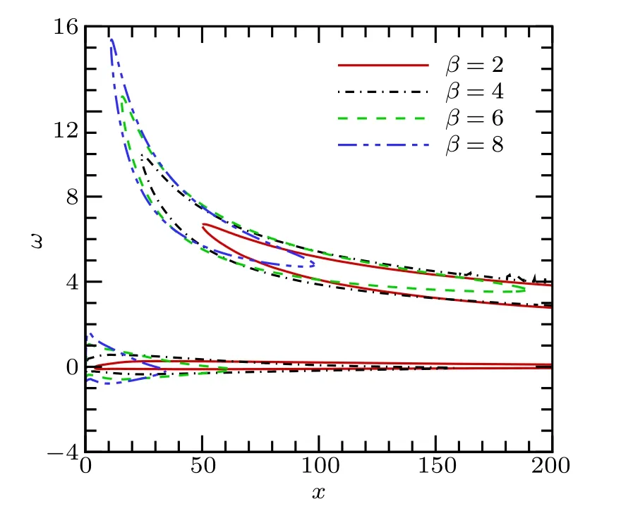
Fig.3. Neutral curves for crossflow mode and second mode with different spanwise wavenumbers β =2,4,6,and 8.
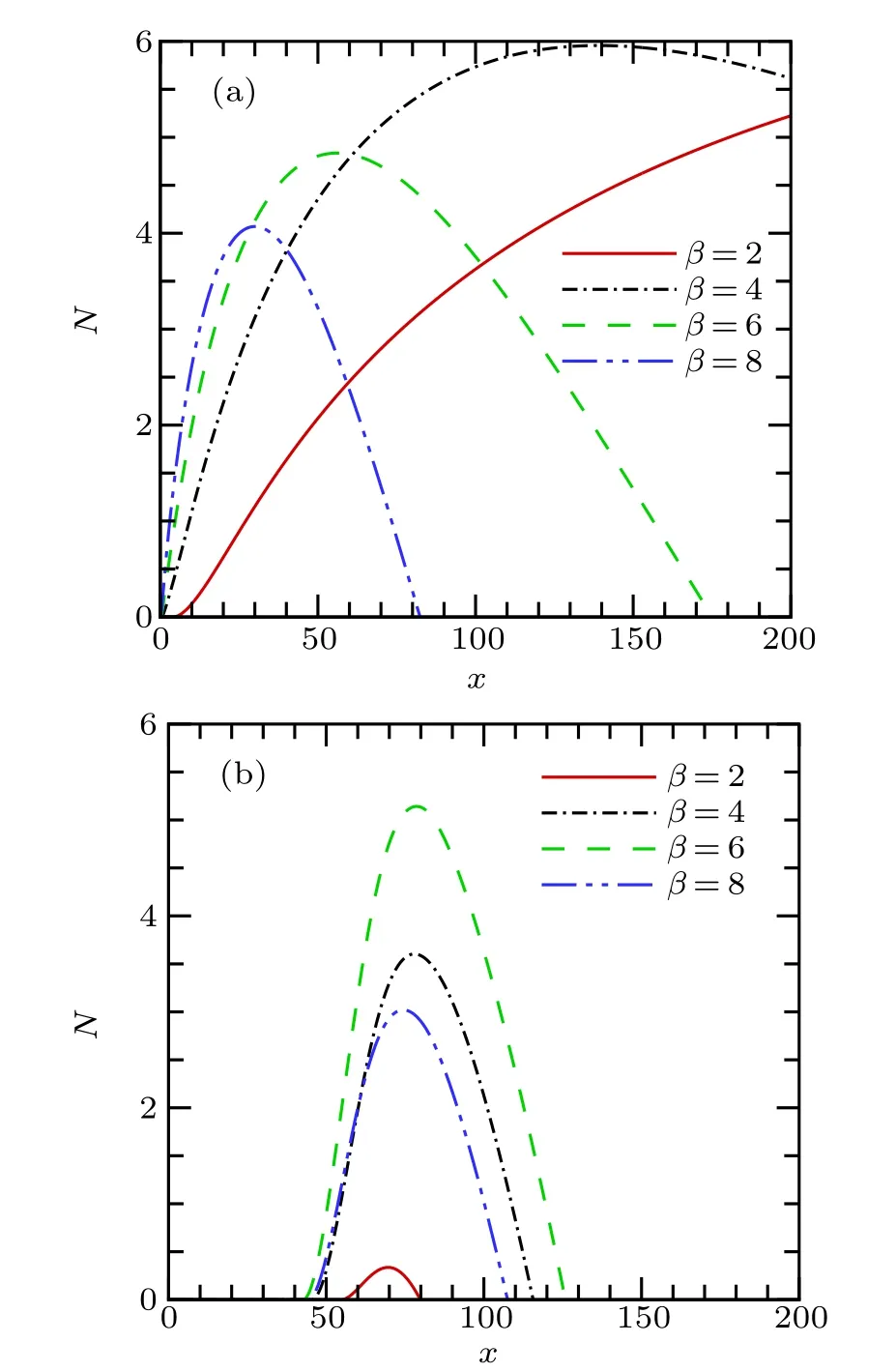
Fig.4. N-factor curves for(a)crossflow mode(frequency ω =0) and(b)second mode(frequency ω =6)with different spanwise wavenumbers β =2,4,6,and 8.
Figure 4 shows the N-factor curves versus the spanwise wavenumbers. The N-factor of an instability wave is defined as

where x0is the position at its lower neutral point, αiis the imaginary part of the streamwise wavenumber α,and −αirepresents the growth rate of disturbances. The N-factor curves represent the amplitude distribution with spanwise wavenumbers. It can be seen that the maximum N-factor of the second mode is equivalent to that of the crossflow mode,we can obtain the linear evolution of the instability modes along the blunt plate provided that all the modes have the same amplitude when they enter the amplified region. However, the Nfactor of the second mode is concentrated in a small range in the x direction. Therefore,the growth rate of the second mode is much larger than that of the crossflow mode in the growth range,and second-mode instability can cause transition. With increasing spanwise wavenumber, the N-factor of the second mode first increases and then decreases,while the N-factor of the crossflow mode increases gradually with decreasing spanwise wavenumber. We can find a stationary crossflow vortex with a large N-factor,which is generated by the nonlinear interaction of two second-mode waves,as shown in Table 1.
Considering the growth range of the second-mode unstable wave,we carefully select the computational domain in the x direction as x=60–90 to simulate the disturbance evolution both with the NPSEs and with DNS.

Table 1. Wave parameters at the inlet x=60.
4. Results and discussion
This section describes the verification of the results for evolution obtained using the improved NPSEs. Three cases with different waves imposed are considered, with the inlet disturbances given in Table 2.
In most previous studies, two fundamental waves (0,1)and(1,0)were imposed at the inlet. Therefore,in case 1 here,they are also imposed to verify the results of the improved NPSEs. In case 2, in which two second-mode waves (1,1)and(1,2)are imposed,the growth rate of the second mode is larger than that of the crossflow mode because of the cooling wall, and the second-mode disturbances play a leading role.Finally, in case 3, where a crossflow-mode wave(0,1)is imposed in addition to the modes imposed in case 2, stationary crossflow vortices will be excited and will be dominant downstream because of the nonlinear effect of second-mode waves.The aim in considering this case is to verify whether or not the imposition of a stationary crossflow vortex has an impact on the robustness of the improved NPSEs.
The fundamental frequency and spanwise wavenumber are ω0=6 and β0=4,respectively,and the initial disturbance amplitudes are all 1×10⁻³. Results are obtained using DNS to verify and validate the predictions of the improved NPSEs.To evaluate the robustness of the improved NPSEs,results obtained using the traditional NPSEs are also given.

Table 2. Waves imposed at the inlet and dominant waves downstream. The fundamental frequency and fundamental spanwise wavenumber are ω0=6 and β0=4,respectively.
4.1. Case 1: two fundamental waves imposed at the inlet
Figures 5(a)and 5(b)show the streamwise evolutions of the amplitudes of the streamwise velocity disturbances corresponding to the crossflow mode (m = 0) and to the second mode (m=1). For clarity, higher harmonics beyond n=3 are not shown here because the amplitude of the harmonic decreases with increasing mode index. Good agreement is observed among the traditional NPSEs, the improved NPSEs,and DNS, and there is no divergence between the traditional NPSEs and NPSEs.

Fig.5.Comparison of disturbance amplitudes obtained using traditional NPSEs, improved NPSEs, and DNS,for different spanwise wavenumbers in case 1: (a)crossflow mode(m=0),(b)second mode(m=1).
Figure 6 shows the real parts of the disturbance streamwise wavenumbers of the crossflow mode and the second mode. The (0,0) wave is in the mean flow distortion, and the real part of the streamwise wavenumber is always zero,so its results are not given here. The fundamental waves(1,0) and (0,1) dominate the evolution, and so their streamwise wavenumbers are calculated using the iterative method in both the traditional and improved NPSEs,and consequently their results agree with those of DNS. For other waves, the traditional NPSEs and DNS continue to agree, because the streamwise wavenumbers of the waves are also calculated using the iterative method. However, the results from the improved NPSEs are obtained using the phase-locked method,and the reference wavenumbers kmand knare directly selected as the real parts of the streamwise wavenumbers of the(1,0)and(0,1)waves. There is a small gap between the improved NPSEs results and the DNS results, and this gap increases with increasing spanwise wavenumber. However, the amplitudes of higher harmonics are very small and it will not affect the precision of amplitude. The gap between the streamwise wavenumbers of non-dominant waves has almost no effect on the amplitude prediction.

Fig.6. Comparison of real parts of disturbance streamwise wavenumbers obtained using traditional NPSEs,improved NPSEs,and DNS,for different spanwise wavenumbers in case 1: (a)crossflow mode(m=0),(b)second mode(m=1).
4.2. Case 2: two nonfundamental waves imposed at the inlet
Figure 7 shows a comparison of disturbance amplitudes obtained using the three approaches. The amplitude of stationary crossflow vortices exceeds that of second-mode waves imposed at the inlet,and they play a leading role downstream.The results from the traditional NPSEs diverge at x=66,because the disturbance energy of high-order harmonics is very small, and then the streamwise wavenumbers converge to the wrong results,as can be seen in Fig.8.
By contrast,the results from the improved NPSEs are the same as those from DNS for the whole computation. Upstream,the dominant waves consist only of the(1,1)and(1,2)waves,and the reference wavenumbers knand kmare given by Eqs. (12) and (13). As the disturbances evolve downstream,the stationary crossflow vortex with the larger amplitude will become a dominant wave. At this time, the dominant waves also include crossflow-mode waves. The reference wavenumbers knand kmcan still be obtained from two nonfundamental waves imposed at the inlet or given by Eqs.(14)and(15).

Fig.7. Comparison of disturbance amplitudes obtained using traditional NPSEs,improved NPSEs,and DNS,for different spanwise wavenumbers in case 2: (a)crossflow mode(m=0),(a)second mode(m=1).

Fig.8. Real parts of disturbance streamwise wavenumbers obtained using traditional NPSEs, for different spanwise wavenumbers in case 2:(a)crossflow mode(m=0),(b)second mode(m=1).
Table 3 summarizes the equations from which the reference waves kmand knare obtained when different methods are adopted. With method I,kmand knare both obtained from two nonfundamental waves imposed at the inlet. With method II,kmis obtained in the same way as with method I, while knis obtained from stationary crossflow vortices that turn into dominant waves. With the improved NPSEs, kmand knare both calculated by considering the dominant waves imposed at the inlet and dominant waves with large amplitude.

Table 3. Equations giving the reference wavenumbers km and kn for different methods.
A comparison of disturbance amplitudes obtained using NPSEs with different methods and using DNS is presented in Fig. 9. The results of methods I and II are both in very good agreement with the DNS results until they diverge downstream. Figure 10(a) shows the real parts of the crossflow mode disturbance streamwise wavenumbers. Because the (0,1) wave turns into a dominant wave, and the streamwise wavenumber is then obtained by an iterative method,the results for the (0,1) wave obtained using NPSEs with different methods and using DNS are consistent. Upstream, when the two second-mode disturbances imposed at the inlet are dominant, the results for the non-dominant waves obtained using different methods are all the same as the DNS results.However,since they no longer play a leading role,the results for the non-dominant waves obtained using method I deviate from the DNS results. The deviation increases as the spanwise wavenumber increases, causing method I to diverge at x=75. The results for the non-dominant waves obtained using method II and using the improved NPSEs are consistent with the DNS results, since the reference wavenumber knis obtained from the stationary crossflow vortex with large amplitude. In Fig. 10(b), the results for the dominant waves(1,1) and (1,2) obtained using NPSEs with different methods also agree well with the DNS results. The results for the non-dominant waves (1,0) and (1,3) obtained using method II deviate from those obtained using DNS. The streamwise wavenumbers of high-order harmonics will also deviate from the correct result,causing method II to diverge at x=78. This indicates that when we calculate the reference wavenumbers kmand kn, we cannot consider just the dominant waves imposed at the inlet,but must also consider dominant waves with large amplitude. Otherwise, the streamwise wavenumbers of non-dominant waves will deviate from the correct results and the NPSEs will diverge.
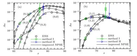
Fig.9. Comparison of disturbance amplitudes obtained using NPSEs with different methods and using DNS,for different spanwise wavenumbers in case 2: (a)crossflow mode(m=0),(b)second mode(m=1).

Fig.10. Comparison of real parts of disturbance streamwise wavenumbers obtained using NPSEs with different methods and using DNS,for different spanwise wavenumbers in case 2: (a)crossflow mode(m=0),(b)second mode(m=1).
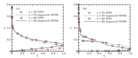
Fig. 11. Normalized profiles of streamwise velocity disturbance components for (a) the (0,1) wave and (b) the (1,0) wave in case 2 at different streamwise positions(x=70 and 80)using the improved NPSEs with nonfundamental waves and using DNS.
Figure 11 shows the normalized profiles of the(0,1)and(1,0)waves at x=70 and 80 in the computational coordinate system. It can be seen from the distribution of the streamwise velocity disturbance component that the results for these two waves obtained using the improved NPSEs at each streamwise position are in good agreement with the DNS results.This indicates that the improved NPSEs can simulate not only the disturbance amplitude and the real part of the streamwise wavenumber,but also the disturbance profile.
4.3. Case 3: multiple waves imposed at the inlet
Comparisons of disturbance amplitudes and the real parts of the streamwise wavenumbers predicted by NPSEs and DNS are plotted in Figs. 12 and 13, respectively. The traditional NPSEs and DNS evolution predictions also agree until the traditional NPSEs marching fails to converge as in case 2. For both the crossflow mode and the second mode,the disturbance amplitudes and the real parts of the streamwise wavenumbers obtained using the improved NPSEs are both consistent with those from DNS.The results for the normalized profiles of the streamwise velocity disturbance component are also the same as those in case 2,so they will no longer be repeated here.

Fig. 12. Comparison of disturbance amplitudes obtained using traditional NPSEs, improved NPSEs, and DNS, for different spanwise wavenumbers in case 3: (a)crossflow mode(m=0),(b)second mode(m=1).

Fig.13. Comparison of real parts of disturbance streamwise wavenumbers obtained using traditional NPSEs,improved NPSEs,and DNS,for different spanwise wavenumbers in case 3: (a)crossflow mode(m=0),(b)second mode(m=1).
It should be noted here that the amplitude of the stationary crossflow vortex(0,1)suddenly increases after x=65,as shown in Fig. 12(a). Figure 14(a) shows normalized profiles of the streamwise velocity disturbances of the crossflow mode and second mode at x=60. It can be seen that the peak profile of the crossflow-mode wave(0,1)is away from the wall,close to the outer edge of the boundary layer, while those of the second-mode waves(1,1)and(1,2)are close to the wall.Figure 14(b) shows the normalized profile of the (0,1) wave at different streamwise positions. Before x=65, the amplitude of the (0,1) wave increases slowly, and its profile is the same as that of the crossflow mode. However,after x=65,the profile of the(0,1)wave is associated with second-mode disturbances. The amplitude of the(0,1)wave increases rapidly because of the nonlinear effect of the second mode. Even though the normalized profile of the (0,1) wave changes, it always remains dominant during its evolution. The real parts of the streamwise wavenumbers of the non-dominant waves can also be obtained from the streamwise wavenumber of the(0,1) wave, and the phase-locked method still applies at this time.

Fig.14. Normalized profiles of streamwise velocity disturbance component:(a)crossflow mode(0,1)and second mode(1,1),(1,2)at the inlet(x=60),(b)(0,1)wave at different streamwise positions(x=60 and 70).
5. Conclusions
The traditional NPSEs will diverge when the disturbances imposed at the inlet no longer play a leading role. Two improvements to the NPSEs have been proposed here to improve the robustness of the approach. First, the disturbance waves are divided into dominant and non-dominant waves. Second,the streamwise wavenumbers of the dominant waves are obtained using an iterative method, while those of the nondominant waves are obtained using the phase-locked method.The calculation methods for the reference wavenumbers kmand knare related to the different conditions of the dominant waves.
The results obtained using the improved NPSEs have been compared with those obtained using the traditional NPSEs and DNS in three cases.When two fundamental waves(1,0) and (0,1) are imposed at the inlet, the results from the improved NPSEs differ slightly in the real parts of the streamwise wavenumbers of the non-dominant disturbances compared with those from DNS. However, this does not affect the evolution predictions, because the amplitudes of the nondominant disturbances are very small. The amplitudes predicted by the improved NPSEs are the same as those predicted by DNS.When two second-mode disturbances(1,1)and(1,2)with the same frequency are imposed at the inlet, stationary crossflow vortices will be excited because of the nonlinear effect of second-mode waves,and the crossflow mode will play a leading role downstream. The traditional NPSEs will fail to converge,because the streamwise wavenumbers of the harmonics diverge. However, the improved NPSEs results are consistent with those of DNS.Since the dominant waves contain stationary crossflow vortices, if the reference wavenumbers are still calculated only from the waves imposed at the inlet, then the NPSEs will also diverge, because the streamwise wavenumbers of the non-dominant waves deviate from the correct results. In this situation, the reference wavenumbers need to be calculated not only from the waves imposed at the inlet, but also from all the dominant waves. When two second-mode waves (1,1) and (1,2) and a crossflow-mode wave (0,1) are imposed, the traditional NPSEs also diverge,whereas the improved NPSEs results agree well with the DNS results. Whether or not the crossflow-mode wave(0,1)is imposed,the improved NPSEs can simulate the evolution of disturbances.
Thus,the evolution of disturbances in different cases can be predicted perfectly by the improved NPSEs. The improved NPSEs are more robust than the traditional NPSEs and can be used to simulate the evolution of disturbances in hypersonic boundary layers.
Appendix A:Effect of threshold amplitude
In this appendix, the effect of the threshold amplitude is investigated. Case 2 is considered, with two nonfundamental waves being imposed at the inlet. Computational results(NPSEs) are presented for two different criteria (geometric mean and minimum)for the dominant waves:

The results are compared with those of DNS and those obtained under the arithmetic mean criterion. The threshold amplitude is adjusted to the geometric mean and the minimum of the dominant waves, respectively. The NPSEs calculation is performed in the same fashion as in the arithmetic mean case.

Table A1. Dominant waves at the outlet under different criteria.
Table A1 gives the dominant waves at the outlet under different criteria. Many waves turn into dominant waves under the minimum criterion. ˜Nw(minimum) at the outlet is the largest, because the amplitude threshold At(minimum)is the smallest among the three criteria. The values of At(arithmetic mean)and At(geometric mean)are similar, and the dominant waves under these two criteria at the outlet are almost the same. Although the dominant waves under the three criteria are different,the results for the disturbance amplitudes obtained using the improved NPSEs under the different criteria are all in close agreement with those from DNS,as shown in Fig.A1.
Figure A2 shows a comparison of the real parts of the streamwise wavenumbers of the disturbance. The results from the NPSEs under the three criteria are very similar, and all are basically consistent with those from DNS. Consequently,the disturbance amplitudes from the improved NPSEs are the same as those from DNS.It has thus been shown that the effect of the amplitude threshold can be neglected,and the improved NPSEs under any of these three criteria can simulate the evolution of disturbances.
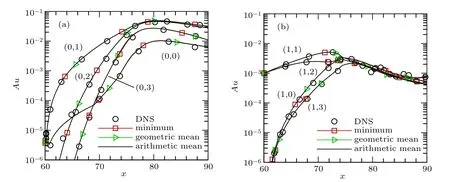
Fig.A1. Comparison of disturbance amplitudes predicted by improved NPSEs under different criteria for different spanwise wavenumbers: (a)crossflow mode(m=0),(b)second mode(m=1). The DNS predictions are also included for comparison.

Fig.A2. Comparison of real parts of disturbance streamwise wavenumbers predicted by improved NPSEs under different criteria for different spanwise wavenumbers: (a)crossflow mode(m=0),(b)second mode(m=1). The DNS predictions are also included for comparison.
Appendix B:Effect of weighted power exponent

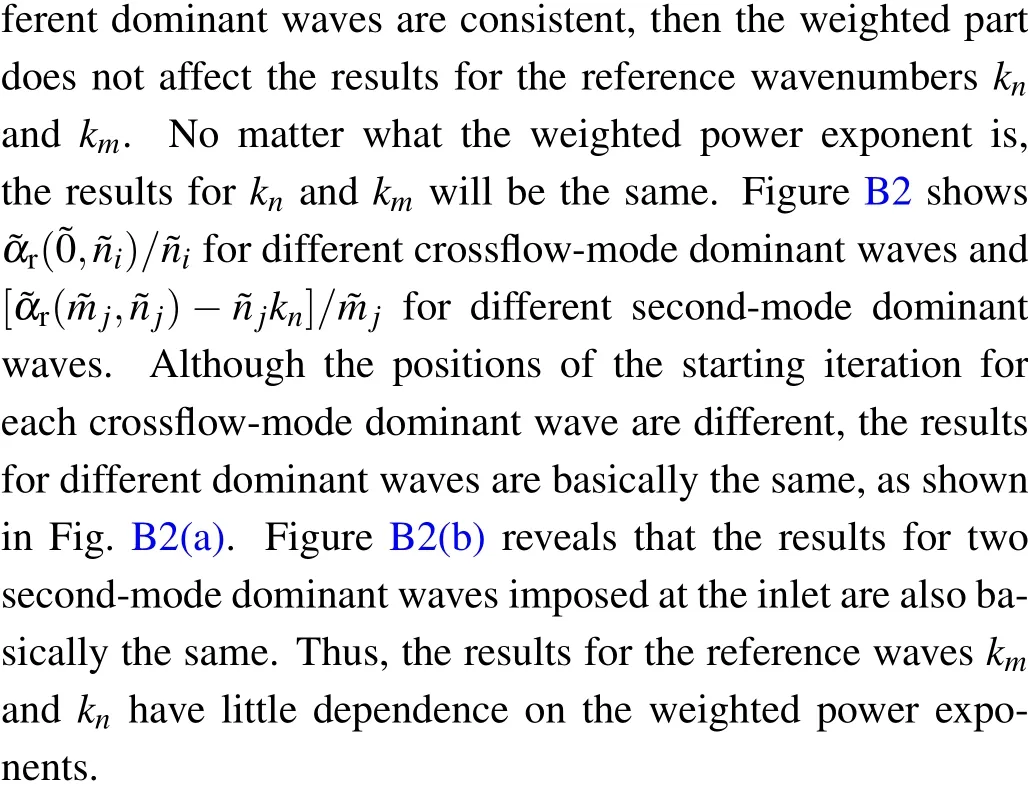

Fig.B1. Comparison of disturbance amplitudes predicted by improved NPSEs with different weighted index numbers for different spanwise wavenumbers: (a)crossflow mode(m=0),(b)second mode(m=1).
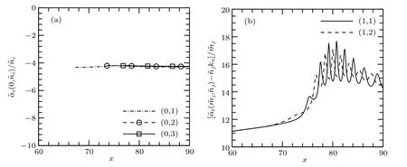
Fig.B2. (a) ˜αr(˜0,˜ni)/˜ni for different crossflow-mode dominant waves. (b)[˜αr(˜mj,˜n j)−˜n jkn]/˜mj for different second-mode dominant waves.
杂志排行
Chinese Physics B的其它文章
- Corrosion behavior of high-level waste container materials Ti and Ti–Pd alloy under long-term gamma irradiation in Beishan groundwater*
- Degradation of β-Ga2O3 Schottky barrier diode under swift heavy ion irradiation*
- Influence of temperature and alloying elements on the threshold displacement energies in concentrated Ni–Fe–Cr alloys*
- Cathodic shift of onset potential on TiO2 nanorod arrays with significantly enhanced visible light photoactivity via nitrogen/cobalt co-implantation*
- Review on ionization and quenching mechanisms of Trichel pulse*
- Thermally induced band hybridization in bilayer-bilayer MoS2/WS2 heterostructure∗
