Extended state observer‑based pressure control for pneumatic actuator servo systems
2021-05-19JohnMohorcicLiliDong
John Mohorcic · Lili Dong
Abstract
Keywords Pneumatic actuator · Pressure control · ESO-based SMC · ADRC · Impedance control module · Stability proof ·Lyapunov approach
1 Introduction
A pneumatic actuator converts energy (typically in the form of compressed air) into linear or rotary mechanical motions.In this paper, we focus on a linear actuator which mainly consists of a cylinder, a piston (or diaphragm attached to a rod), and valves. The piston separates the cylinder into two chambers. When compressed air at high pressure moves into the back chamber and the front chamber is exhausted, the net force on the piston pushes the assembly forward, and vice versa. As the same force (induced by air pressure) is applied to both chambers, there is no movement [1]. Valves connected to the actuator allows air to flow into or out of each chamber. An external controller can turn on or off the valves to control the air flow and thus the pressure. Being a highly reliable, efficient, and safe source of motion control, a pneumatic actuator has been one of the most popular engineering devices in industry. They are broadly applied to automation and manufacturing process such as pick and place motion,robot manipulation, packing, clamping, broaching, and drilling etc. [1]. These applications typically require fast and accurate positioning. Improving positioning control has thus remained an enduring research issue. As mentioned above, the positioning control of pneumatic actuators can be implemented through regulating and directing air flow in chambers via valves. As air mass flow changes, air pressure varies, which in turn changes the force on the piston [2], and hence alters the positions of piston incrementally. It has been confirmed the effectiveness of pressure control on enhancing the performance of pneumatic position servo systems [3].
However, the nonlinearity, system uncertainties, and disturbances pose challenges on position servo control of pneumatic actuators. Due to the compressibility of air and delay of valves, the governing dynamic equation of the pneumatic actuator is nonlinear [4]. In addition, intermittent loss of air and pressure (caused by imperfect sealing)and variations of load and friction [5] introduce uncertainty and disturbance to the pneumatic actuator system. To overcome the issues, different pressure control strategies have been applied to pneumatic actuators. Typically, pressure control is combined with position control to form a position servo system as given in [6-9]. Pressure control can also act as an independent control method such as the one in [10-13]. In [6, 7], a PI controller is designed to control the air pressure, while a position controller is constructed based on the controlled pressure. Extra feedforward loops and disturbance observers are utilized in [6] and [7], respectively, to “counterbalance the friction force and parameter changes”. In [8], a PID controller with feedback linearization is used in the pressure control inner loop, and another PID controller is employed in the position control outer loop. In addition to [8], feedback linearization is reported in[9-11] on position tracking control of pneumatic actuators.The linearization method provides “theoretic guidance at the initial stage of controller design and leads to a simpler tracking control strategy” [11]. However, its effectiveness is dependent on accurate mathematical model of the actuator and is not robust enough against modeling uncertainties.As an independent control approach, both open-loop and closed-loop pressure control have been generated. The openloop pressure control, as introduced in [12], is based on the working curve between input voltage and output pressure of a proportional valve. Open-loop pressure control has simple structure and is easy to implement. However, it cannot compensate for disturbances and system parameter variations.Among closed-loop robust control loops which involve pressure sensors, a linear quadratic Gaussian (LQG) self-tuning pressure regulator is utilized to control the pressure based on online estimation of system parameters [13]. Compared with open-loop pressure control, the LQG self-tuning controller is more adaptive to variable parameters such as the volume of the chamber and the setting pressure. In addition,intelligent controllers such as hybrid fuzzy PID [14] and fuzzy force feedback controllers [15] are applied to adjust the pressure of pneumatic systems where fuzzy controller handles structured uncertainty. Although adaptive and intelligent controllers are robust against parameter variations,they do not cope well with external disturbances. To reduce the effect of disturbances, sliding mode controller (SMC)has been employed to regulate the pressure of pneumatic actuators [3, 16, 17]. Sliding mode control is also an effective method for positioning control [18-21]. Constructed on the assumption that the unknown terms in the actuator model are bounded, SMC provides an efficient way to maintain system stability in the presence of modeling imprecision and disturbance [18]. As indicated in [3, 16-21], SMC is a proven method to increase the performance of pneumatic position servo system.
In [22-24], an extended state observer (ESO) is created for active disturbance rejection controller (ADRC), which integrates ESO with a feedback controller for motion control. The ESO estimates not only system states, but also a generalized disturbance which includes both external disturbance and unknown internal dynamics. Thus, it is a robust estimator for the uncertain systems [24]. Recently, ESO has been embedded in adaptive controller and SMC [23, 24]due to its simple configuration with only one tuning parameter (i.e., observer bandwidth) and good observation performance. Especially in [24], an ESO-based SMC successfully controlled the piston position of a pneumatic actuator.However, the dynamics for air pressure is disregarded in [24]because “it will complicate the control loop” for positioning.“For simplicity” of controller design, only the dynamics of piston position is considered in [24].
In this paper, an ESO-based SMC is developed based on both piston-load dynamics and chamber pressure model. A single closed-loop position servo system is constructed for pressure and position controls. Compared to double control loops in [6-9], the single control loop has simpler structure.Our control objective is to drive the piston to reach a goal position through regulating the air pressure in chambers.To this end, an impedance control module, which regulates the relationship between force and position of the piston,is originally designed and combined with the ESO-based SMC. While the former is employed to produce a reference pressure level based on desired position, the latter regulates the pressure output of chambers to follow the setpoint. In addition, the extended state of the ESO can approximate the external disturbances and model uncertainties (or generalized disturbance) caused by an air leak, friction, and environmental changes. A SMC then compensates for the estimated generalized disturbance. Therefore, the robustness and stability of the control system are achieved. Unlike the adaptive and intelligent control algorithms in [13-15] where there are at least five tuning parameters, the proposed control system has three tuning parameters (one observer bandwidth for ESO and two controller gains for SMC), making it computationally tractable and easier to implement. In this paper, the ESO-based SMC is compared with classic ADRC and SMC in terms of position tracking and robustness via simulations. The stability of the proposed control system is proved through Lyapunov approach.
The rest of this paper is organized as follows. The dynamics of load-piston and chamber pressure model are presented in Sect. 2. The ESO-based SMC, ADRC and classic SMC are developed on a pneumatic actuator in Sect. 3. The simulation results are demonstrated in Sect. 4. Concluding remarks and future research are given in Sect. 5.
2 Modeling of pneumatic actuators
A linear pneumatic actuator typically “includes a force element (cylinder), a command device (valve), and position and pressure sensors” [25]. It is driven by compressed air through valves and outputs displacement.
2.1 Piston‑load dynamics
The cylinder consists of a piston, rod, and two chambers.The difference between the air pressure in two chambers determines the position, force, and compliance of the piston.The force diagram of piston and load is shown in Fig. 1.

Fig. 1 Force diagram of piston and load [25]

Fig. 2 Pneumatic valves connected to chamber 1
In Fig. 1,P1(t) andP2(t) are the absolute air pressures for chambers 1 and 2 respectively,FL(t) is payload force,Ff(t) is coulomb friction,βis viscous friction coefficient,MPis mass of the piston,MLis mass of the load, andPa(t)is the atmospheric pressure. The parameterAprefers to the area of the smaller rod portion of the piston, whileA1represents the area of larger disc portion of the piston that divides chambers 1 and 2, andA2is the difference betweenA1andAp. From [25], the piston-load dynamics can be modeled as

wherex(t) is piston position. The right side of (1) “represents the actuator active force, produced by the different pressures acting on the opposite sides of the piston” [25]. To control the piston position, one must “finely tune the pressure levels in the cylinder chambers using the pneumatic valve” [25].
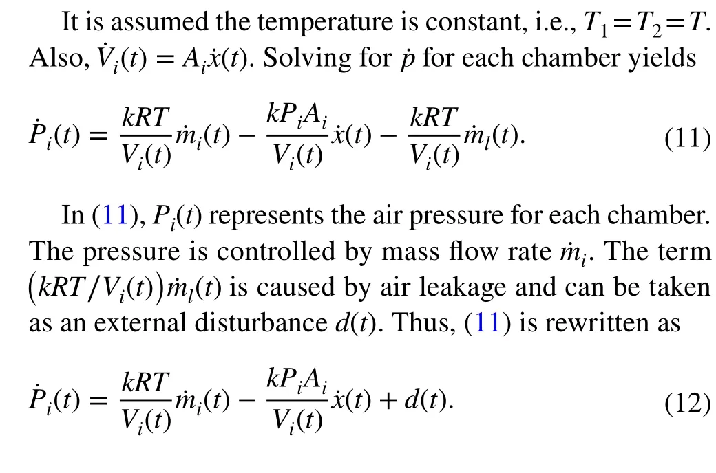
2.2 Chamber pressure model
We suppose the compressed air (or gas) enters chamber 1 and exists chamber 2. According to [25-27], the heat exchange within the respective chambers is represented by
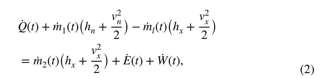
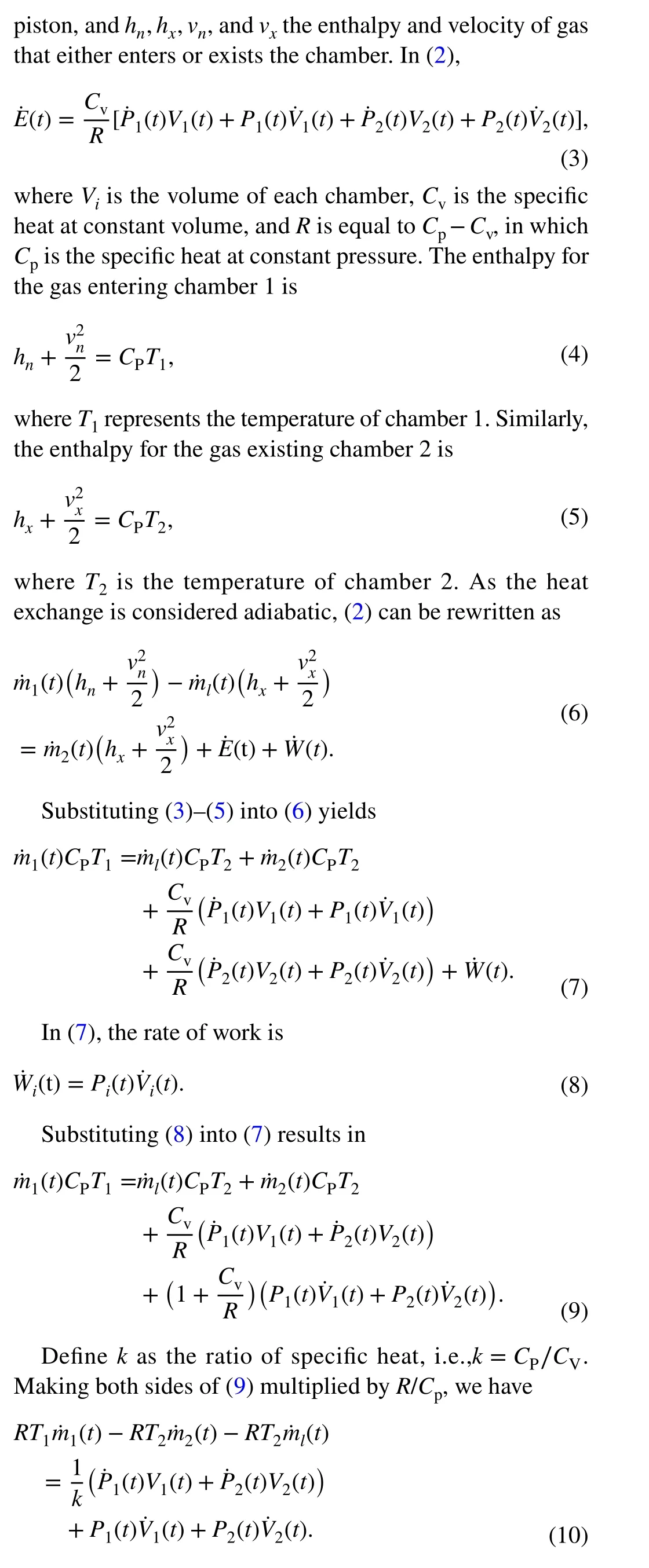
where˙Q(t) is the heat rate for the air volume,˙mithe mass flow rate for each chamber (where subscriptiindicates chamber number andi=1 or 2 ),˙mlthe mass flow rate of air leakage due to imperfect sealing of cylinder,˙E(t) the rate of change of total energy,˙W(t) the rate of work delivered to
2.3 Valve model
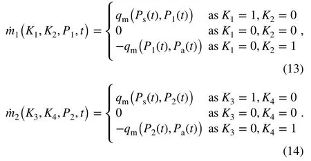
As shown in Fig. 1, there are two chambers in one cylinder.“One chamber is connected to the pressure tank through the supply path, and the compressed air will flow inward.The other chamber is connected to the atmosphere through the exhaust path, and the air will flow outward” [25]. Each cylinder chamber is attached to a pair of valves. Figure 2 shows the two valves tied to chamber 1. The pair of valves for each chamber is mutually exclusive so that air cannot be injected and expelled simultaneously. In Fig. 2,Kirepresents the on/off state of each valve andPs(t) is supply pressure. As valve 1 is on (K1= 1), the compressed air will be supplied to chamber 1. As valve 2 is on (K2= 1), the air in chamber 1 will flow outward.
Therefore, the mass flow rates for chambers 1 and 2 can be represented by (13) and (14) whereqm(defined in [25])is a function ofPs(t), and/orPi(t), and/orPa(t).
As one turns on/off different valves, the air mass flow rate will change accordingly. We can control the air pressure for each chamber through varying mass flow rate.
3 Controller design
The control objective is to regulate the piston to a desired position through adjusting the air pressure in the presence of external disturbance and parameter variations. A block diagram of the pneumatic position servo control system is given in Fig. 3, wherexdis desired position,PDis desired pressure,u(t) is control signal,P(t) is the pressure output of each chamber, and˙x(t) is velocity. The purpose of impedance control module is to producePDaccording toxd. The control system makesP(t) trackPD. In this section, ESO and SMC are introduced first. Then, the ESO-based SMC is derived on the grounds of ESO and SMC.
3.1 Impedance control module
Mechanical impedance is defined as force divided by velocity. Thus, if a motion is taken as an input and force as an output, an impedance equation can be established to derive the force from motion. The impedance control module merely represents a mass-spring-damper behavior that regulates force to displacement, velocity, and acceleration. In this section, such a module will be created to yield a desired pressure from a desired positionxd. Equation (1) can be rewritten as

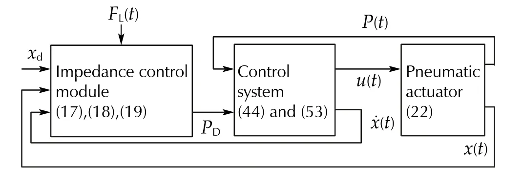
Fig. 3 Block diagram of pneumatic servo control system
In (18) and (19),P1D(t) andP2D(t) are the desired pressures for chambers 1 and 2, respectively,Psum(t) is a chosen parameter for the total supplied pressure, andPa(t) is known.Thus, solving (18) and (19) will produceP1D(t) andP2D(t) ,which can be utilized as reference signals for pressure control. For simplicity, the subscripti(i=1 or 2) is disregarded in the rest of Sect. 3 as the same controller can be designed on each chamber.
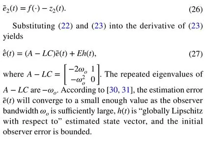
3.2 Extended state observer

3.3 Sliding mode controller
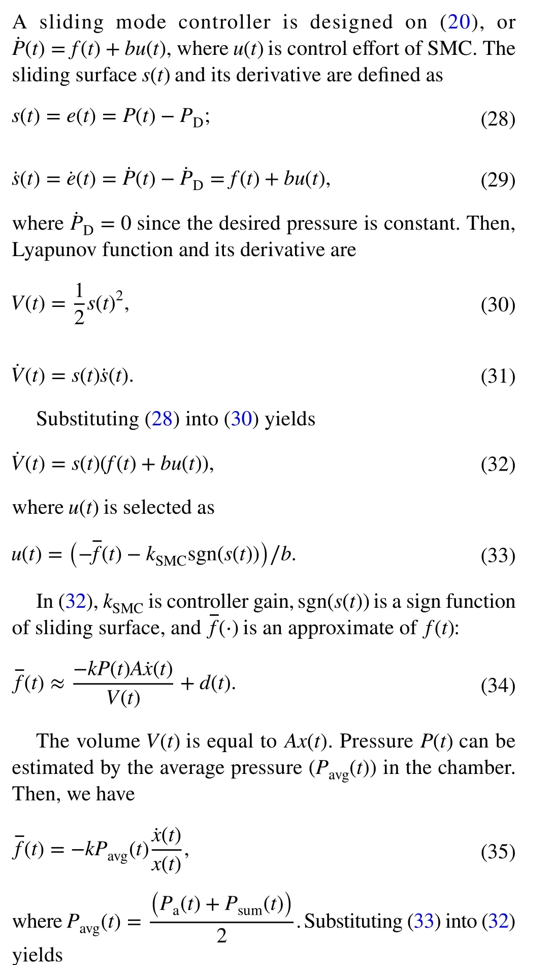

whereΦ(t) is one of the tuning parameters for SMC.
3.4 ESO‑based SMC
In Sect. 3.3, the SMC is developed based on the assumption that the feedback signals of position, velocity, and pressure,and the bound of external disturbance are available. In practice, velocity is typically “obtained by differentiation of the position signal with a digital Butterworth low-pass filter”[19]. Thus, the measurement of velocity signal is prone to errors and bandwidth fluctuations [2]. In addition, the bound of disturbance is unknown. Thus, the accurate information of velocity and disturbance are absent in the real world. In this section, to make the SMC more practical, ESO is added to the control system to estimate generalized disturbance which contains both velocity and external disturbance. Based on the outputs of ESO, SMC can effectively reduce the effect of disturbance. In addition, ESO only has one tuning parameterωo. Therefore, it does not add much complexity to the controller design.
The ESO in (22) is rewritten as

To reduce chattering effect, the sign function in (53) can be replaced by a saturation function as given by (43), wheresis replaced byz1-PD.
4 Simulation results
In this section, ESO-based SMC is compared with classic ADRC and SMC. According to [22-24], the control law for ADRC is designed as

whereωcis the controller bandwidth and a positive real number. The ADRC is a state feedback controller based on estimated statesz1(t) andz2(t) from ESO. In (54), the difference betweenPDandz1is tracking error. Both (23) and(54) constitute the ADRC control system. The SMC control law is given by (42). As shown in Fig. 3, ESO-based SMC is represented by (44) and (53). Three controllers are simulated on the pneumatic actuator (described by (22)), respectively.Our control objectives are to drive the piston to desired position through adjusting the air pressure to required level. To change air pressure, control commands need to turn on or off valves to direct the air flow into or out of each chamber.Frequent on and off commands will wear out the valves.Thus, we also aim at producing the least excitation signals to valves. The performances of these three controllers are compared in terms of position tracking, pressure regulation,amount of control effort (required to excite valves), as well as robustness against system uncertainties and disturbances.From [25-28], the system parameter values are listed in Table 1, which shows the reference model for impedance control module is critically damped. The controller parameters are selected as in Table 2. For fair comparison, three controllers are tuned such that the magnitudes of their control efforts are comparable. Although ADRC has a simpler structure than ESO-based SMC, the controller parameters of the former have much larger values than that of the latter (asshown in Table 2). This is because ADRC is derived from tracking error while ESO-based SMC is built on the bound of tracking error. The reduced controller gains (for ESObased SMC) are advantageous for practical exercises where small gains are easy to implement.
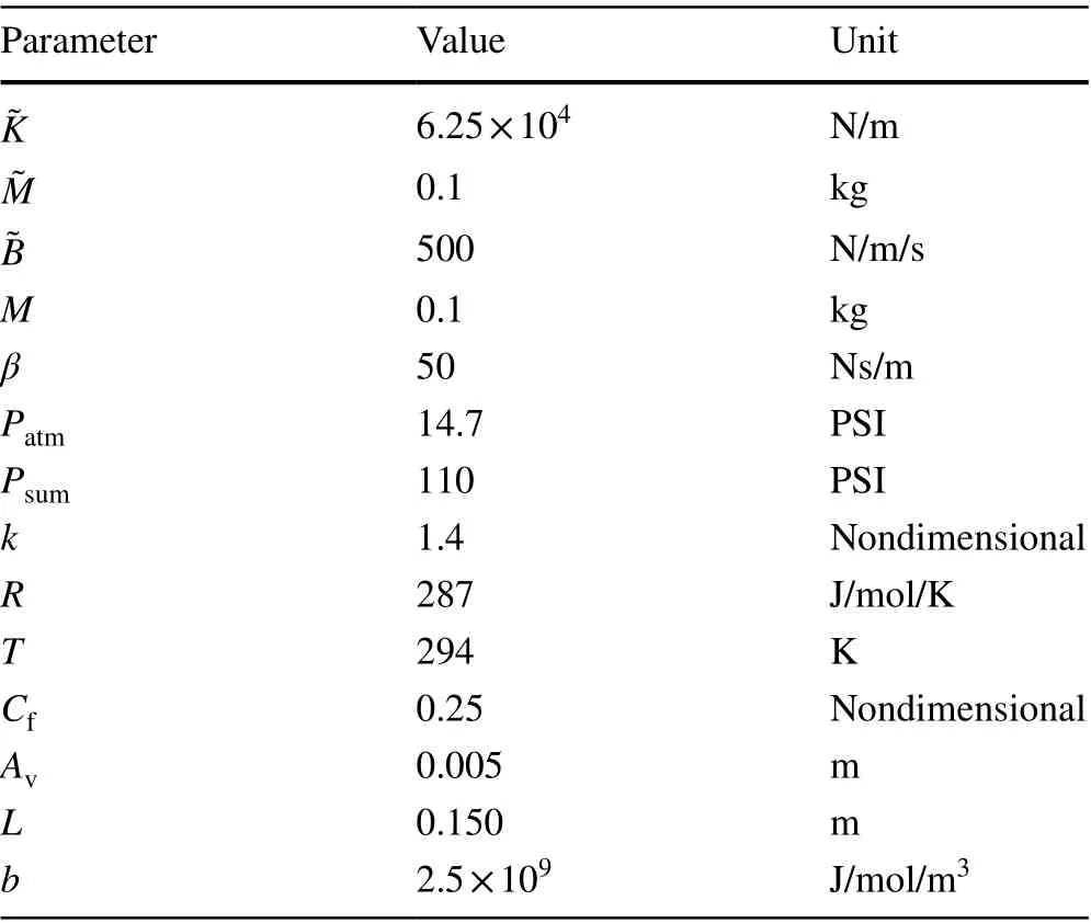
Table 1 System parameters
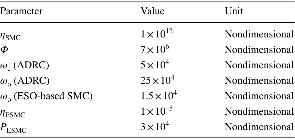
Table 2 Controller parameters
4.1 Pressure control and position tracking
The goal of the pneumatic position servo control system is to command the piston to any position within the cylinder.While position is not directly regulated by the controllers, it is a direct outcome of the controlled pressure in each chamber. Figure 4 shows the position outputs of three controllers and reference trajectory. As seen in Fig. 4, the position changes att=0.2 s and 0.4 s , respectively. Figure 5 shows the steady-state errors (SSE) in the position outputs. The average SSE for ADRC is 4.2 × 10⁻⁹m, for ESO-based SMC is 2.5 × 10⁻⁹m, and for SMC is - 1.7 × 10⁻⁷m. Although all three controllers can drive the piston to reference position,the ESO-based SMC provides the smallest SSE. The SSE of SMC is consistently below zero. Therefore, the tracking performance of SMC is worse than the other two. The chamber pressures under three controllers are shown in Fig. 6.As reference position varies, the chamber pressures change accordingly to push the piston to the goal position. Among three controllers, only SMC controlled pressure has an overshoot att=0.4 s . The performances of ADRC and ESObased SMC are equivalent in pressure regulation.
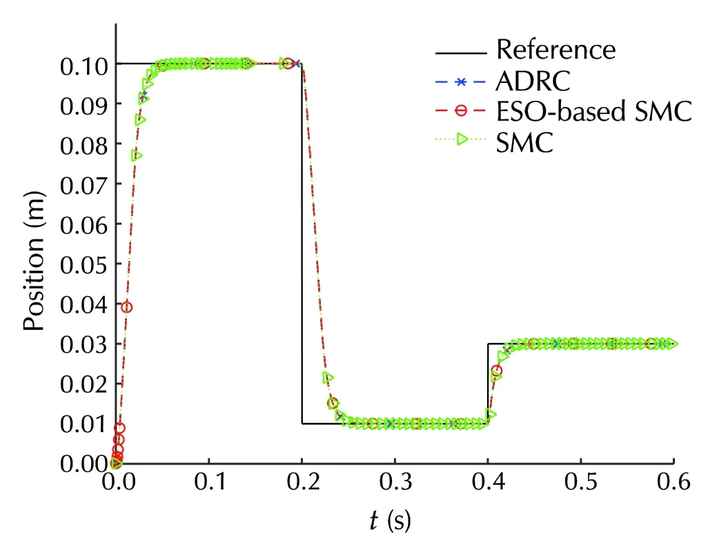
Fig. 4 Position outputs
Figure 7 shows the SSEs for chamber pressures. Specifically, it displays the error between desired and measured pressures. In Fig. 7, “Ch. 1” represents chamber 1, and “Ch.2” represents chamber 2. The average SSEs for ESO-based SMC and ADRC are almost 0.05 kPa and 1 kPa, respectively. However, the SSE for SMC is about 5 kPa. SMC shows the largest SSE. As discussed in Sect. 2, positive mass flow rate turns on valve 1 to provide supply pressure.Negative mass flow rate turns on valve 2 to exhaust air. If the mass flow rate is zero, both valves are off. The excitations of these valves must be scrutinized since they will degrade the mechanical parts gradually. Figure 8 shows the valve states in chamber 1 under the controls of ESO-based SMC, ADRC, and SMC. From simulation, we can see that SMC excites the valves most frequently, and hence has the worst performance among the three controllers. ESO-based SMC performs slightly better than ADRC, particularly at the beginning of the simulation. During the simulation period,ESO-based SMC switches the valves every 1.2 ms on average, ADRC switches the valves every 0.6 ms on average, and SMC switches the valves every 27 μs on average. From [27],the switching valve can change its state on a microsecond timescale to adapt the rapid change of pressure. Thus, both ESO-based SMC and ADRC are feasible. The control efforts of three controllers are shown in Fig. 9. While the average magnitudes of the controllers are nearly the same, SMC exhibits spikes and chattering in the effort. Thus, ESO-based SMC and ADRC outperform SMC.

Fig. 6 Desired and actual chamber pressure for a ESO-based SMC, b ADRC, and c SMC

Fig. 7 SSEs for chamber pressures under the control of a ESO-based SMC, b ADRC, and c SMC
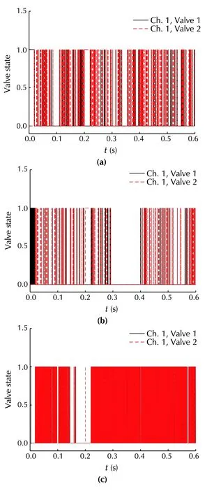
Fig. 8 Valve states in chamber 1 with a ESO-based SMC, b ADRC,and c SMC

Fig. 9 Control effort of a ESO-based SMC, b ADRC, and c SMC

Fig. 10 Position outputs with parameter variations
Figure 4 through Fig. 9 show that ADRC, ESO-based SMC and SMC successfully drive the piston to desired positions through adjusting chamber pressures to required levels using comparable amount of control efforts. Thus, the control goal is achieved by the three controllers. With that being said, ESO-based SMC outperforms the other two controllers in that it produces the least frequently changing signals to excite valves. In addition, it has smaller controller gains than ADRC and SMC. Thus, it is pragmatic and feasible. On the other hand, SMC shows chattering in its control effort, and excites the valves most frequently. Therefore, it is not an ideal choice compared to the other two. In the next section,we aim to test the robustness of the three controllers.
4.2 Robust analysis

Fig. 11 Pressure outputs with parameter variations: a ESO-based SMC, b ADRC, and c SMC
First, we vary the system parameter values to introduce structured uncertainty to the pneumatic actuator system.The impedance parameters are varied withincreased by 1%,reduced by 80%, andreduced by 95%. Therefore, the impedance system remains critically damped. The position outputs of three control systems are illustrated in Fig. 10. Despite the presence of parameter variations, all three controllers drive the piston to desired positions but with a bit longer settling time than the one in Fig. 5. This is expected because friction force is increased with the change of impedance parameters. The resulting chamber pressure and control efforts are shown in Figs. 11 and 12, respectively, where ADRC and ESO-based SMC show comparable performances, while SMC displays overshoots in pressure outputs and chattering effects in its control effort. The average magnitudes of three control signals are almost same.
Subsequently, we need to test the robustness of the three controllers against external disturbance. An air leak is a common problem in a pneumatic actuator system. It could be caused by a loose connection, a hole in the tubing, or wear to a seal and so on. Here, a step disturbance representing a sudden air leak is added to the chamber pressure model att=0.5 s . Figures 13 through 16 show how three control systems respond to the disturbance. The position outputs,the chamber pressure, and control efforts are depicted in Figs. 13, 14, 15, and 16, respectively. Despite the presence of the disturbance, the three controllers command the piston to the desired positions. Both ESO-based SMC and ADRC effectively compensate for the disturbance. However, the SMC yields SSE in position output aftert=0.5 s (as shown in Fig. 14).
In addition, ADRC and ESO-based SMC successfully control the chamber pressures to desired levels with equivalent amount of control efforts (see Figs. 15 and 16). There are no noticeable fluctuations in the position and pressure responses of ADRC and ESO-based SMC, even with the existing disturbance. However, SMC shows evident chattering in the control input.
4.3 Conclusions

Fig. 12 Control efforts of a ESO-based SMC, b ADRC, and c SMC in the presence of parameter variations
In this paper, an ESO-based SMC is developed to improve the performance of a pneumatic position servo system through regulating the air pressure of each chamber in the pneumatic cylinder. ESO, an accurate observer that was originally used in ADRC, is applied to estimate the velocity and generalized disturbance. SMC, a proven method for positioning pneumatic actuators, is employed to control the air pressure based on the estimated states of ESO. ESO and SMC form a robust controller that can successfully drive the piston to desired position through regulating the air pressure,despite the presence of system uncertainty and external disturbance. The Lyapunov approach proves the stability of the control system. In addition, for comparison purposes, both ADRC and SMC are designed and applied to control the air pressure, respectively. The performances of three controllers(i.e., ADRC, ESO-based SMC and SMC) are evaluated in simulation. For a fair assessment, the three controllers are tuned in a way such that the average magnitudes of control efforts are nearly the same. It is shown that both ADRC and ESO-based SMC outperform SMC in terms of robustness and control effort. When it comes to pressure regulation and positioning, ADRC and ESO-based SMC demonstrate equivalent results. Nevertheless, ESO-based SMC produces less valve excitation than ADRC to accomplish the control goal, particularly at the beginning of the simulation. In addition, ESO-based SMC requires smaller controller gains than both ADRC and SMC.
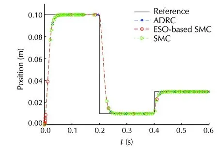
Fig. 13 Position outputs with input disturbance

Fig. 14 Zoom-in view of position outputs as t = 0.5-0.55 s
One contribution of the paper is the original and successful development of ESO-based SMC for the pressure control of a pneumatic position servo system. Another contribution is the establishment of impedance control module, on which the ESO-based SMC is constructed. The impedance control module translates the desired position to required air pressure level for each chamber. With the module, piston-load dynamics and chamber pressure model are connected in such a way that it enables the controller to position the actuator through regulating air pressure.
In the future, we plan to implement the ADRC and ESObased SMC on a real pneumatic actuator. The experimental results are expected to match the simulation results presented in the paper.

Fig. 15 Chamber pressure in the presence of disturbance under the control of a ESO-based SMC, b ADRC, and c SMC
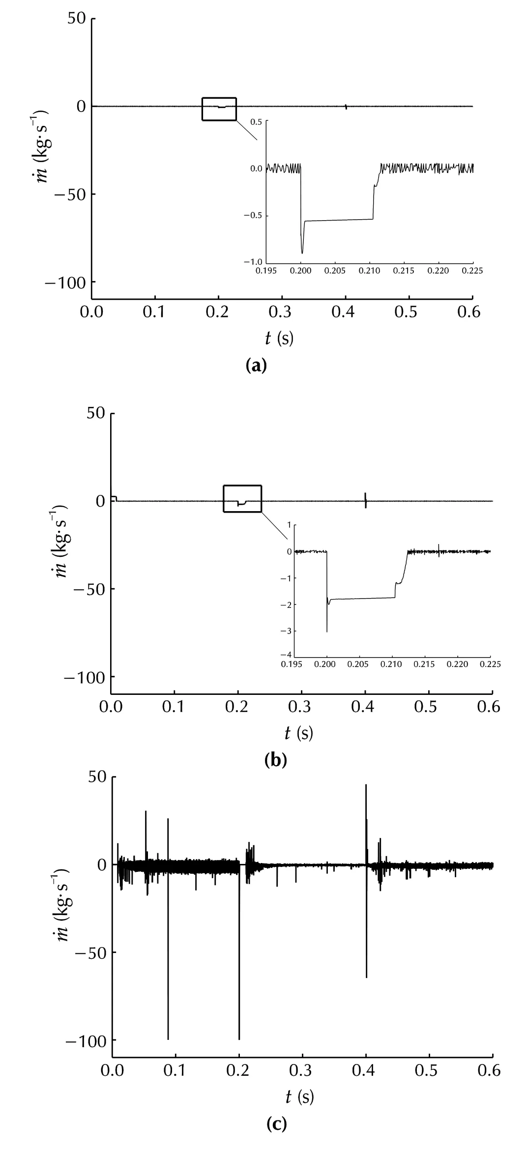
Fig. 16 Control efforts of a ESO-based SMC, b ADRC, and c SMC in the presence of disturbance
杂志排行

Control Theory and Technology的其它文章
- Simplifying ADRC design with error‑based framework: case study of a DC-DC buck power converter
- A phase‑locked loop using ESO‑based loop filter for grid‑connected converter: performance analysis
- Tuning of active disturbance rejection control for differentially flat systems under an ultimate boundedness analysis: a unified integer‑fractional approach
- Data‑driven disturbance observer‑based control: an active disturbance rejection approach
- On transitioning from PID to ADRC in thermal power plants
- Recent advances on distributed online optimization