Impact of bending dies with different friction forms on forming force and quality of tubes manufactured by free bending technology
2021-05-14HaoCHENHuiWANGAliABDELATYYaoQINJiangLIYongZHANGTaoLIXunzhongGUO
Hao CHEN, Hui WANG, Ali ABD EL-ATY, Yao QIN, Jiang LI,Yong ZHANG, Tao LI, Xunzhong GUO,*
a College of Material Science and Technology, Nanjing University of Aeronautics and Astronautics, Nanjing 211100, China
b College of Mechanical and Electrical Engineering, Nanjing University of Aeronautics and Astronautics, Nanjing 210016, China
c Jiangsu Key Laboratory of Nuclear Energy Equipment Materials Engineering, Nanjing University of Aeronautics and Astronautics, Nanjing 211100, China
d Mechanical Engineering Department, Faculty of Engineering-Helwan, Helwan University, Cairo, Egypt
e Nanjing Golden Dragon Bus Co., Ltd, Nanjing 210012, China
KEYWORDS Bending die;Cross-section distortion;Rolling friction;Sliding friction;Spherical bearing force;Wall thickness
Abstract In the 3D free bending forming system,the bending die can be designed either in a sliding type or rolling friction type.Bending die-based sliding friction type is often called normal bending dies;however,the bending dies-based rolling friction type includes bending die-based roller type and ball type in structure.In the current study,the impact of three bending dies on the forming force,and the bent tube quality was investigated.The obtained results showed that the tangential stresses and strains of the tubes formed by the bending die-based roller type were the smallest among the three bending dies.Besides,the spherical bearing force PU was reduced drastically after using the roller type and ball type compared to the sliding friction type.Moreover,the uniformity of the wall thickness distribution of the tubes formed by the roller type and ball type was better than those obtained from the sliding friction type.In addition,the cross-section distortion rate was reduced by 2.8%using the roller type,and 1.8%using ball-type compared to the sliding friction type.
1. Introduction
Metal hollow components with various cross-section shapes possess a broad range of applications in aircraft, aerospace,marine, and nuclear industries due to their excellent weightreducing performanceand good corrosion resistance.Curved pipes with complex shapes play a crucial role in the oil circuit system and pneumatic system of the commercial aircraft.The force exerted on the surface and inside of the tube during forming is large,which is easy to make the stresses and wall thickness of tubes unevenly distributed, and the cut and scratch are more serious.Therefore, the structure of the bending dies,and the contact formwith tubes have higher requirements. Based on the needs of the forming quality and the service life of the equipment, bending dies can be designed in different friction forms.The most typical friction forms are sliding frictionand rolling friction contact.Bending diebased sliding friction type is often called normal bending dies,while the bending dies-based rolling friction type includes bending die-based roller type and bending die-based ball type in structure.
In recent years,several studies were accomplished to investigate the influence of the forming force during the forming process,and the impact of the rolling structures on the forming effect of bending components. For instance, Hu and Wangproposed a new model that improves upon traditional rollbending processes.The proposed new model can not only solve the shortcomings of the conventional roll bending process but also made the forming of large-size bending components more flexible. Hu et al.proposed a new process for the manufacturing of three-dimensional sheet components. With the assistance of bendable rollers,continuous flexible bending of sheets can be achieved.Feng and Champliauddealt with the prediction of the position of the lateral roller during cylindrical roll bending. The position of the lateral roll, which determines the final radius of the bent cylinder, is predicted by numerical simulations.Li et al.explored to study the spread effects and the radius development,in which the stable forming conditions and the modelling technologies such as mass scaling and mesh convergence were correctly solved in the roll-bending process.Kim et al.proposed a theoretical model for predicting the final forming radius of the three-roller tube bending. This model considered the influence of many parameters, such as the strength and thickness of the steel plate,the size of the rollers, the distance between the bottom rollers and so on. Kagzi and Ravalstudied the forces and coefficient of friction during cylindrical three roller bending. They calculated the forces and friction coefficient at each roller-plate interface combining theoretical models and experimental results. Chudasama and Ravaldeveloped the prediction model of force during the stage of three-roller dynamic bending, which will be useful to understand the complex mechanics of the process.Zhao et al.established a mechanical model of the static bending stage in the three-roller setting round process according to the physical relationship of elastic-plastic deformation, the deformation coordination and the constraint condition. Based on the hyperbolic sine-type constitutive law,Yang et al.investigated the deformation behavior of 7050 aluminum alloy during roll bending with the help of finite element simulations. Chiew et al.employed a numerical simulation method to simulate the roller bending process and calculate the residual stress.Besides, they also investigated some key roll bending process parameters on the bending component stress distributions.Badr et al.developed a constitutive material model for Ti-6Al-4 V to predict springback behavior in roll forming and V-die bending at room temperature. And the model was the first to reproduce the lower springback experimentally observed for roll forming compared to V-die bending. Wang et al.developed an improved theoretical prediction model considering the neutral layer shift, to improve the prediction accuracy for springback of Z-section profiles in the four-roll bending process.
Based on the aforementioned discussion, it is clear that the influence of different friction forms between bending die and tubes and adding rolling components on the forming force,and the final quality of bent tubes manufactured by free bending technology are not investigated yet. Thus, in this study,finite element simulations of the free bending forming process and actual trials of free bending experiments using bending die-based sliding friction type and bending dies-based roller type and ball type were carried out. Firstly, the tangential stresses and strain distributions of the inner and outer sides of the tube after forming by different bending dies were studied. Furthermore, the spherical bearing force Pof a single bending section forming system was extracted.The wall thickness of the tube inner and outer walls was observed, and the cross-section distortion was measured in different positions.
2. Characterization of tube material
The material of the tubes used in this study is AA6061-T6, so the specimens of a specific size and shape were cut and subjected to a tensile experiment to characterize the mechanical properties of the tube. The dimensions of the tensile specimen are depicted in Fig. 1. The data obtained from tensile testing was used to obtain the stress-strain curve of the tube material,as described in Fig. 2.
3. Theoretical analysis
3.1.Design of bending die-based sliding friction and bending diebased rolling friction types
Bending dies-based rolling friction type were added with the rolling friction assembly and the fixed clamping assembly according to the bending die-based sliding friction type. In the current investigation, two design forms for the bending dies-based rolling friction types were proposed according to the degree of the envelope of the tube.
3.1.1. Design of bending die-based sliding friction

Fig. 1 Detailed dimensions of tensile specimen.

Fig. 2 True stress-strain curve of AA6061-T6 alloy.
The bending die in the form of sliding friction contact is shown in Fig. 3. Among them, the smooth contact corners of the bending die are used to avoid excessive scratching of the tube due to excessive forming force. In terms of the contact area,the form of contact between the bending die and the tube is line contact, and the contact shape is a circular arc. The tube always maintains relative movement with the bending die during continuous feeding,and the contact part of the bending die with the tube does not change with the feeding of the tube.
3.1.2. Design of bending die-based ball-type
The components of the bending die-based ball type are depicted in Fig. 4. Bending die-based ball type is mainly composed of a bending die, an inner ball bushing, an outer ball bushing, and a plurality of balls. The inner bushing and the outer bushing jointly hold the balls which were in contact with the tube.The distance from the center of all balls to the center of the tube is R=R+D/2+Δc,where, R(ball center is the geometry center of balls)is the distance from tube axis to ball center,R(tube outer wall is the outer wall of tube)is the radius of tube outer wall,Dis the ball diameter, Δc is the value of the clearance between the tube and the balls.
3.1.3. Design of bending die-based roller type
The components of the bending die-based roller type are presented in Fig.5.Bending die-based roller type mainly includes a bending die, four rollers, an inner roller bushing, an outer roller bushing, and connecting bolts. The inner bushing and the outer bushing jointly hold the rollers which were in contact with the tube. In contrast, the inner and outer bushings and rollers were connected by bolts to prevent the nondirectional sliding of the rollers in the bending die.As depicted in Fig. 5, the rollers were designed as two pairs of mutually perpendicular structures. The two pairs of mutually vertical rollers were in line contact with the tube, and the envelope has a circular cross-section with an angle up to 360 degrees.

Fig. 3 Schematic description of bending die-based sliding friction type.

Fig. 4 Schematic diagram of bending die-based ball type and balls distribution.

Fig. 5 Schematic description of bending die-based roller type and rollers distribution.
3.2. Principles of free bending using bending dies-based rolling friction type
The principles of the free bending based on bending dies-based rolling friction type are shown in Fig. 6. The feeding mechanism drove the tube through the guider and the bending dies-based rolling friction type,as well as the spherical bearing in sequence; besides, bending die moved under the constraints of the spherical bearing to form tubes. During the rotation of the bending die, the rolling friction assembly was passively rotated by contacting the tube. Thereby changing the contact form from sliding friction to rolling friction.
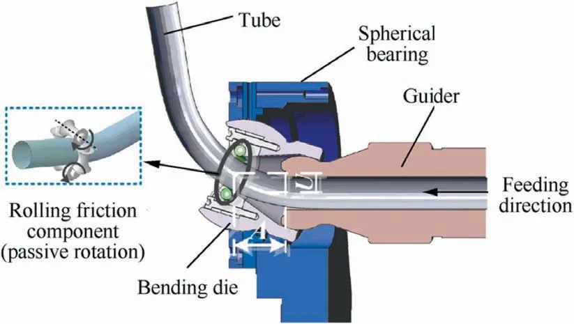
Fig. 6 Schematic description of free bending forming principle based on bending dies-based rolling friction type.
3.3. Theoretical analysis of free bending process-based rolling friction type bending dies
Due to the different friction forms of the bending die,the contact friction conditions between the bending dies,and the tube was mostly different.Thus,the influence of the friction force Fon the mechanical analysis needs to be considered.
Based on the above analysis, this paper proposed a free bending forming stress-strain analysis method,adding the friction force Fbetween the bending dies and tube. Firstly the Hollomon equation σ=Kε(σ is the stress, K is the plastic coefficient,ε is the strain,n is the hardening index)was selected as the material model. The following assumptions were made:(1)The cross-section of the tube before and after bending kept perpendicular to the central axis of the tube;(2)Deformation due to transverse shear is not taken into account;(3)The bending deformation of the tube conformed to the condition of volume invariance and the circumferential strain (ε, φ is the circumferential direction) in-plane is about zero.
In a perpendicular direction to the tube feeding, the spherical bearing applied a force Pto the tube.When the tube fed through bending die and guider, the bending inner rotating members passively rotated, and the friction force F(F>0)which perpendicular to the rotating direction of the bending die applied to the tube.
In horizontal direction:
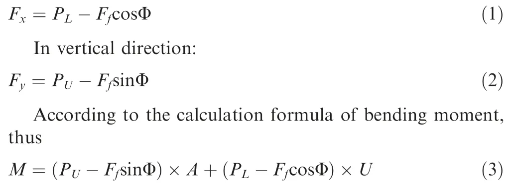
where, U is the distance of the center of the bending die offset from the equilibrium position,A is the distance from the center of the bending die to the front end of the guider, Pis the equipment axial thrust, Φ is the angle of bending die from the initial position.
As shown in Fig. 7, the tube is in a three-direction stressstrain state. Where R, Rrepresent the radius of bending strain and original neutral layer; R, Rrepresent the radius of the inner and outer bend; ρ represents the radius at any point of the bend; r, rrepresent the radius of tube inner and outer sides; rrepresents any point radius on the section of the tube;β represents the offset angle of strain neutral layer;δ represents the angle between the arbitrary radial line and original central layer.
It is assumed that σ(σis the radial stress of the bend),σ(σis the tangential stress of the bend)and the transverse stress σ(σis the circumferential stress of the bend) which is perpendicular to the curved plane is the principle stresses. For the reciprocal of θ (θ is the tangential direction of tube), τ(shear stress on the bending radial plane) and τ(shear stress on the bending tangential plane)were both zero,the stress balance differential equation can be simplified to


Fig. 7 3D free bending mechanics analysis based on bending dies-based rolling friction type.


where σis the tangential compressive stress caused by axial thrust.

where, in Eq. (10), C is integration constant.

According to the definition of stress, combined with the bending moment M by the bending dies-based rolling friction type, it can obtain that

where trepresents the original tube wall thickness, drepresents the outer diameter of the tube section.
At the inner and outer side surfaces ρ=R-r,ρ=R+rin the bending section, σ=0; at the strain neutral layer ρ=R,σis continuous.The integral constant inside and outside of the bending was determined as follow:
Substitute the obtained integral constant into Eq. (10), the radial stresses on the inner and outer sides were expressed as:


Fig. 8 Analysis of tube section distortion.
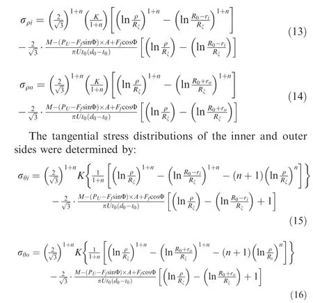
According to Eqs.(9),(13)-(16),the equivalent stress distribution of the bending inner and outer sides were acquired by:

In the stress solution formula (P-FsinΦ)×A+FcosΦ= P(μcosΦ+μcosΦsinΦA-A), since μcosΦ is less than 1, the effect on the equation is small, so the formula is approximated as PA(μcosΦsinΦ-1). As Pdecreases, the value of the entire equation increases,indicating that the axial thrust stress σincreases, and the bending moment remains constant, so the tangential stress σdecreases.

Fig. 9 Schematic diagram of finite element model.
Because of the radial and tangential compressive stresses exist, the cross-section of tubes will be distorted after free bending forming,and the cross-section shape becomes approximately oval. The size of the cross-section distortion rate is generally measured by the ellipticity. As shown in Fig. 8,assuming that the maximum radial distance (long axis) and the minimum radial distance (short axis) of the tube are measured, the outer diameter of the tube is D, the Eq. (19)is used to calculate the distortion in production.

where Dis the maximum radial distance (long axis) of the tube (after deformation), Dis the minimum radial distance(short axis) of the tube (after deformation).
As depicted in Fig.8,under this bending state,the stress on the outer side section is σ+σ,and on the inner side section is σ. The magnitude σdepends on the friction force F;therefore, from a theoretical analysis aspect, after formed by two bending dies in rolling friction contact, the stresses on both the inner and outer sides are smaller than the bending die in the form of sliding friction contact. Eventually, the distortion of the cross-section is better than that of the bending die in the form of sliding friction contact.
4. Finite element modelling of the free bending process
4.1. Description of finite element model and process parameters
To understand the impacts of varying bending dies on the forming force and final quality of bent tubes,the finite element simulation of free bending process-based different friction type bending dies was performed.The mesh of each component was divided according to a particular scale, as depicted in Fig. 9.
The deformation properties of the forming system components are discrete non-deformable rigid bodies, and the tube can be regarded as a uniform deformable shell. Thus, in this model, the discrete rigid bodies such as spherical bearing system,guider,and curved in-die rolling components meshed with a 4-nodes rigid element (R3D4). The bending die was set as a deformable solid part,so the meshing used an 8-nodes hexahedral linear element (C3D8R). The tube was defined as a deformable shell, so 4-nodes curved shell element (S4R) with hourglass control and reduced integration was used to divide the mesh. The contact form is universal contact, the analysis step is dynamic explicit, and the mass scaling factor is 1,000,000 times. The related parameters of the simulation based on the forming system are listed in Table 1.
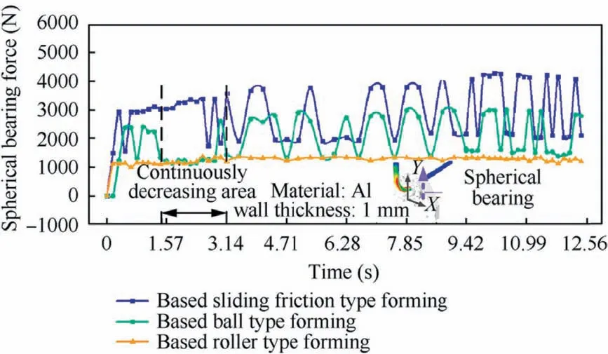
Fig.10 Schematic diagram of spherical bearing force in forming processes using different bending dies.
4.2.Impact of different bending dies on the forming force during the free bending process
To investigate the impact of different bending dies on the forming force during the bending forming process, the spherical force was separately extracted. Furthermore, the reasons for the difference in results due to the difference in bending dies were analyzed.
As presented in Fig. 10, for the aforementioned 90 degrees tube fitting,the spherical bearing force during the whole forming process was extracted and studied.It was observed that the spherical bearing force reduced significantly around 2000 N after using the bending dies-based ball type and roller type,especially during the period from 1.3 s to 3.14 s. In the period from the start moving of the bending die to the stable bending forming position,the value of the Pforce reduction is particularly obvious. Besides, the maximum value was exceeded drastically 2500 N. Furthermore, the spherical bearing force stability during the bending process using the bending diebased ball type was remarkable.
This is because after using the bending dies-based rolling friction type, the friction force between the bending die and the tube was reduced. The tube material flow was smoother during the forming process, and the spherical bearing force on the tube was also reduced. What’s more, from the theoretical analysis in 3.3, it can be seen that the spherical bearing force on the tube was reduced,which can reduce the tube tangential stresses after forming.
4.3. The influence of bending die with varying forms of friction on the forming of the tubes
To study the effects in forming tubes with different bending dies, the finite element simulations using bending die-based sliding friction type, bending die-based ball type, and bending die-based roller type were accomplished.The simulations used three different structures of bending dies to form a 90 degrees member with the bending radius of 70 mm. After theoretical calculation, the bending dies will be offset center by 6.75 mm. The simulation results are presented in Fig. 11.
It was observed from Figs.11 and 12,judging from the results of the tensile and compressive tangential stresses on the outer and inner sides of the tube,the bending die-based sliding friction type was the largest,the bending die-based ball type was the second,the bending die-based roller type were the smallest.and the high tangential stress distribution areas of tube inner and outer sides were small,and the stress distributions were more uniform.From the results and the analysis in the previous section,it was noticed that adding the rollers or balls to the bending die can effectively reduce the friction force between the tube and the bending die.Meanwhile,decrease the spherical bearing force,so that the tube inner and outer sides tangential stresses were reduced and distributed evenly. Besides, the bending die-based roller type was more effective in reducing the tangential stresses on the inner and outer sides of bent tubes than the bending die-based ball type.This is due to the contact areas between the rollers and tubes were larger than that of the balls and tubes,which can better reduce the friction force F. The structure of the rollers made the stresses evenly distributed to each part of the bending section better than the structure of the balls.
From the aspect of strain,the outer tensile tangential strain was PE22=0.118,and the inner compressive tangential strain was PE22=-0.142 of the tube formed by bending die-based sliding friction type. The outer tensile tangential strain was PE22=0.107, and the inner compressive tangential strain was PE22=-0.129 of the tube formed by bending diebased ball type. The outer tensile tangential strain was PE22=0.098, and the inner compressive tangential strain was PE22=-0.112 of the tubes formed by bending diebased roller type. The tangential strains of tube inner and outer sides formed by the three different bending dies showed the same law as the tangential stresses.
As observed in Fig. 13, the outer sidewall thickness was 0.92 mm, and the inner sidewall thickness was 1.16 mm for the tube formed by bending die-based sliding friction type.The outer sidewall thickness was 0.94 mm,and the inner sidewall thickness was 1.13 mm for the tube formed by bending die-based ball type.The outer sidewall thickness was 0.97 mm,and the inner sidewall thickness was 1.08 mm for the tube formed by a bending diebased roller type.Since after adding the rollers or balls structure,the tangential tensile and compressive strains of tube outer and inner sides were reduced. Therefore, compared with the tubes formed by the bending die-based sliding friction type,the amount of reduction in the outer sidewall thickness wall was reduced.Atthe same time,the amount of increase in the inner sidewall thickness was also reduced of tubes formed by the bending dies-based roller or ball type.

Table 1 Setting parameters related to the finite element model.

Fig. 11 Schematic diagram of tangential stress distributions after forming with different bending dies.

Fig. 12 Schematic diagram of inner and outer side tangential stresses and strains of formed tubes.
5. Experiments of free bending process using different bending dies

Fig. 13 Schematic diagram of wall thickness of formed tubes.

Fig. 14 Critical components of bending die-based roller type.
Based on the results obtained from the finite element simulation, free bending experiments were performed. Before the experiments, the components of bending die-based roller type and bending die-based ball type were assembled. The critical components of these two dies are depicted in Figs. 14 and 15. The outer spherical bearing structure of the two bending dies are universal. Only the inner rolling components and the inner and outer bushings for holding the rolling components were replaced. The actual forming experiments were carried out based on these two bending dies and bending die-based sliding friction type. The radius of the single bending section was set to 70 mm, and the bending angle was 90 degrees.
5.1. Comparison of the forming forces during deformation using different bending dies
Because the forming force of the equipment in the actual experiment is affected by many other factors,only the relevant process parameters of the equipment and the actual working condition parameters are considered.The relationship between the forming force and the process parameters is approximately calculated based on this consideration.
Assume that the torque of the servo motor controlling the spherical bearing movement of the equipment is T, P is the motor power, n is the motor rotating speed, the torque is F,the torque radius is R, the line speed is v, the motor voltage is U, and the electric current is I. The relationship between the torque of the motor and the generated force is derived as follows:

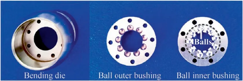
Fig. 15 Critical components of bending die-based ball type.

Fig. 16 Schematic diagram of spherical bearing force PU measuring equipment.
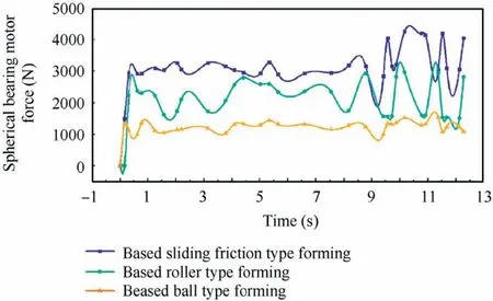
Fig. 17 Schematic diagram of spherical bearing conversion force.

Fig.18 Schematic diagram of tubes formed by different bending dies.
In the uniform speed operation, the torque of the screw is not accurately calculated,which can be solved by the following equation:

where l is the lead screw stroke, nis the positive efficiency of the screw feed.
Combine the Eqs.(23)and(24);it can be obtained that the equation P=59998UIcosφn/(nl). Therefore, by monitoring the electric current of the servo motor of the spherical shaft of the equipment control, the magnitude of the spherical bearing forming force can be approximately calculated (Fig. 16).
The electric currents of the spherical bearing motion motors during the three bending dies forming processes were obtained.It is converted into the forming force according to the calculation formula, as shown in Fig. 17. It can be seen from the results that the spherical bearing force of each bending die obtained in the actual forming experiments is approximately the same as the simulation results. The reliability of the simulation results is verified, and it is shown that the bending diesbased ball type and roller type can effectively reduce the forming force during the forming experiment.
5.2. Comparison of forming quality of tubes formed by different bending dies

Fig.19 Wall thickness distributions of measuring points of bent tubes.

Fig. 20 Cross-section distortion of measuring points of bent tubes.
The bent tubes formed by different bending dies with varying forms of friction are presented in Fig. 18. Compared with the bending die-based roller type or ball type, still, there is a certain amount of occasional scratch on the outer wall of the bent tube formed by bending die-based sliding friction type. It can be drawn from the analysis in 5.1 that in the actual forming experiment, two kinds of bending dies-based rolling friction type can effectively reduce the forming force of the spherical bearing. The decrease in the spherical bearing force indicated that the force between the bending die and the tube outer contact surfaces was reduced. Thus, the scratching of the tubes formed by the bending die-based sliding friction type was improved effectively.
The change in diameter and the wall thickness of each part of the tube was measured based on the point-taking method as introduced in Fig. 18. Furthermore, the wall thickness distributions and cross-section distortion of each part were also obtained as depicted in Figs. 19 and 20.
It was observed that the inner sidewall thickness was 1.16 mm,outer sidewall thickness was 0.90 mm,and the distortion rate was 7.3%of the tube after the bending die-based sliding friction type forming. Furthermore, it was 1.13 mm,0.93 mm, 5.5% of the tube after the bending die-based ball type forming and 1.09 mm, 0.96 mm, 4.5% of the tube after the bending die-based roller-type forming. At the 2-9 measuring points where the bending movement was stable, the inner and outer sidewall thickness was 1.14 mm, 0.92 mm, the cross-section distortion rate of the tube was evenly 7.8% after the bending die-based sliding friction type forming. Besides, it was 1.10 mm,0.94 mm,6.0%of the tube after the bending diebased ball type forming and 1.06 mm, 0.97 mm, 5.0% of the tube after the bending die-based roller-type forming.
From the experimental wall thickness data,the bending diebased roller type or ball type can effectively improve the thickness reduction or thickening of the outer and inner sidewalls of the tube. The cross-section distortion rate was reduced by 2.8%using bending die-based roller type,1.8%using bending die-based ball type compared to the bending die-based sliding friction type.
Thus, bending die-based roller type or ball type can lower the cross-section distortion rate of the tube forming process.This is because the die-based roller type or ball type reduced the tangential stresses on the inner and outer sides of the bent tube,and the stress distributions were more uniform.Furthermore, the radial stresses on the inner and outer sides of the tube were also reduced, and the wall thickness distribution was improved. The cross-section distortion rate was also reduced.
6. Conclusion
In this study,the influences of using different bending dies with varying forms of friction on the forming force,and the quality of tubes manufactured by free bending technology was investigated. Based on the results acquired from the current investigating, the main conclusions can be deduced as follows:
(1) The tangential stresses and strains of the inner and the outer sides of the bent tube section after using the bending die-based roller type were smaller than those obtained from by using the bending die-based ball type,and tangential stresses and strains of the bending diebased the sliding friction type were the largest.
(2) After using the bending die-based roller type or ball type,the spherical bearing force was reduced drastically compared to the bending die-based sliding friction type.
(3) The wall thickness distribution uniformity of the tubes formed by the roller type and ball type was better than that obtained from the sliding friction type. Besides,the cross-section distortion of the tube after using bending die-based roller type or ball type in the free bending process was improved. Furthermore, the cross-section distortion rate was reduced by 2.8% using bending die-based roller type,1.8%using bending die-based ball type.
Declaration of Competing Interest
The authors declare that they have no known competing financial interests or personal relationships that could have appeared to influence the work reported in this paper.
Acknowledgement
sThe investigation was supported from the Jiangsu Province Key Research and Development Project (No. BE2019007-2),Opening Project of Jiangsu Key Laboratory of Advanced Structural Materials and Application Technology of China(No. ASMA201903) and National Natural Science Foundation of China (No. U1937206).
杂志排行
CHINESE JOURNAL OF AERONAUTICS的其它文章
- Time delay compensation in lateral-directional flight control systems at high angles of attack
- Dual stability enhancement mechanisms of axial-slot casing treatment in a high-speed mixed-flow compressor with various tip clearances
- Development cost prediction of general aviation aircraft using combined estimation technique
- Improvement on shaped-hole film cooling effectiveness by integrating upstream sand-dune-shaped ramps
- Modeling and parameter identification of linear time-varying systems based on adaptive chirplet transform under random excitation
- An experimental method to obtain the hard alpha anomaly distribution for titanium alloy aeroengine disks
