Visual Object Tracking and Servoing Control of a Nano-Scale Quadrotor: System, Algorithms,and Experiments
2021-04-22YuzhenLiuZiyangMengSeniorMemberIEEEYaoZouandMingCaoSeniorMemberIEEE
Yuzhen Liu, Ziyang Meng, Senior Member, IEEE, Yao Zou, and Ming Cao, Senior Member, IEEE
Abstract—There are two main trends in the development of unmanned aerial vehicle (UAV) technologies: miniaturization and intellectualization, in which realizing object tracking capabilities for a nano-scale UAV is one of the most challenging problems. In this paper, we present a visual object tracking and servoing control system utilizing a tailor-made 38 g nano-scale quadrotor.A lightweight visual module is integrated to enable object tracking capabilities, and a micro positioning deck is mounted to provide accurate pose estimation. In order to be robust against object appearance variations, a novel object tracking algorithm,denoted by RMCTer, is proposed, which integrates a powerful short-term tracking module and an efficient long-term processing module. In particular, the long-term processing module can provide additional object information and modify the short-term tracking model in a timely manner. Furthermore, a positionbased visual servoing control method is proposed for the quadrotor, where an adaptive tracking controller is designed by leveraging backstepping and adaptive techniques. Stable and accurate object tracking is achieved even under disturbances.Experimental results are presented to demonstrate the high accuracy and stability of the whole tracking system.
I. INTRODUCTION
IN recent years, the study of UAVs has attracted increasing attention from both industrial and academic communities.Miniaturization is one of the major trends of the development of UAV technologies. In 2019, DJI-innovations1https://www.dji.com/cnlaunched a small quadrotor named the “ Mavic mini”, which is the smallest of their products. However, it still weighs 249 g with a volume of 245 mm ×290 mm ×55 mm. Most of commercial UAVs, even micro UAVs (with weights between 0.4–2 lbs or 180–907 g [1]) can easily cause damage to their surroundings. In contrast, nano-scale UAVs [2]–[6] (with weights below 0.4 lb or 180 g) have advantages including safe and silent operation, and are suitable for flying in a tightly constrained environment and in batches [7]. In 2005, the defense advanced research projects agency (DARPA)announced the nano air vehicle (NAV) program, whose goal was to design a nano unmanned air vehicle (size under 75 mm,total mass under 10 g) with the capabilities including continuous hovering, forward flying, and being able to perform indoor and outdoor missions.
In addition to miniaturization, intellectualization is another major trend in the development of UAV technologies. In particular, in order to excute various tasks in many practical applications (e.g., surveillance, augmented reality, environmental monitoring, behavior modeling, rescue, and search),the capability of autonomous object tracking is indispensable[5]–[14]. For example, the authors of [13] apply an open-TLD(tracking-learning-detection) [15] tracker on a UAV platform,i.e., AR Drone 2.0, to accomplish the task of tracking nonartificial targets including people or moving cars. However,the TLD-based approach cannot achieve comparable performance to state-of-the-art tracking algorithms. Li et al.[14] realize a vision-based pedestrian tracking system on the UAV platform DJI Matrice100 by exploiting the well-known correlation filter-based tracker. In particular, a frequency domain correlation filter acts as the base tracker, and its online training model is further transformed to the spatial domain to obtain the re-detection model. Since the detection classifier depends on the accuracy of the base tracking model and the generic object proposal [16], this method still cannot efficiently deal with situations where there are variations in object appearance. The above research works focus on relatively large UAV platforms. In contrast, few research works involving visual object tracking use nano-scale UAV platforms due to their very limited volume size, payload ability and power consumption. Firstly, a majority of existing onboard localization and navigation sensors cannot be mounted on nano-scale UAVs, which include a GPS module,laser range finders and normal cameras. Moreover, most existing state-of-the-art visual object tracking solutions require a significant amount of computation resources, and thus, they are not available to be directly employed on nanoscale UAVs. Last but not least, the flight of the nano-scale UAVs is more susceptible to the external disturbances due to their light weight and small volume. Srisamosorn et al. [4] use a nano-scale quadrotor to realize person tracking with the use of multiple environmental cameras. In [5], Briod propose an ego-motion estimation algorithm for use with a 46 g nanoscale UAV by using an optical flow sensor. However, the position error drifts to 50 cm within two minutes. In [6],Palossi et al. use a nano-scale quadrotor to track a red target,but the average tracking error is shown to be larger than 30 cm. In addition, since the adopted object tracking method depends on color features, it is easily disturbed by the external environment. To sum things up, due to volume and weight limitations, as well as difficulties of designing an effective visual tracking algorithm and robust visual servoing controller, it is still a challenging task to obtain stable and accurate visual object tracking using a nano-scale UAV less than 40 g. We now provide a detailed survey on the study of visual object tracking algorithms and visual servoing control algorithms.
Typical visual object tracking approaches have been recently proposed in [11], [14], [15], and [17]–[24]. In particular, early template-based methods take advantage of selectively updating template and multiple key frames to find an optimal patch to describe object appearance [14].Moreover, discriminative approaches [11], [17], [18] have been proposed, and both the foreground and background information is considered from sequential images. In [11], two linear support vector machine (SVM) classifiers are trained with simple local binary pattern (LBP) features to detect and track a drogue object during aerial refueling. In addition, the correlation filter-based tracker [19]–[22] emerges as one of the most successful and popular tracking frameworks due to its promising performance and computational efficiency. In particular, Bolme et al. [19] leverage the correlation filterbased method to achieve object tracking, in which the minimum output sum of squared error (MOSSE) filter is proposed with an operation speed of 669 frames per second(FPS). Henriques et al. [20] propose a popular correlation filter-based object tracking algorithm, denoted by kernelized correlation filter (KCF), where the kernel technique is used to improve performance by allowing classification on a rich,high-dimensional feature space. The fact that cyclic matrices can be diagonalized in the Fourier space is leveraged to significantly speed up the matrix operation. However, because most of the aforementioned tracking methods employ relatively risky update schemes and are based on the spatiotemporal consistency of visual cues, they can only be used to handle short-term tracking. In other words, the tracking errors will inevitably be accumulated during longterm tracking, and the lack of robustness against the variations of object appearance (e.g., changes in geometry/photometry,different camera viewpoints, partial occlusion, or object disappearing) usually leads to tracking failure in challenging scenarios. On the other hand, some state-of-the-art object detection methods based on deep-learning (e.g., YOLOv3[23], MASK R-CNN [24]) have been proposed, and are shown to be robust with excellent detection accuracy.However, the required computations are significant and may lead to the poor real-time performance on CPU or average performance GPU platforms.
In parallel, visual servoing control methods [25]–[29] can be classified into two major categories: image-based visual servoing (IBVS) and position-based visual servoing (PBVS)depending on whether the image measurements from the camera are directly implemented in the control loop. In the IBVS scheme, the controller is designed using twodimensional pixel coordinates from the image plane. In [25],Zheng et al. propose an IBVS controller for a quadrotor. The trajectories of the image moment features are first designed,following the definition in the virtual image plane. Then, a feature trajectory tracking controller is proposed to track the designed trajectories. In contrast, the PBVS controller requires the reconstruction of the three-dimensional Cartesian coordinates of the observed object from visual data. The main advantage of PBVS is that the control law is precisely formulated in the Cartesian coordinate space such that the control problem (computation of the feedback signal) is separated from the pose estimation problem. In general, PBVS control can be resolved into two sub-tasks: relative position estimation (between the object and the UAV) and trajectory tracking controller design. In particular, most of existing methods need the prior model information of object or depth data measured by sensors (e.g., RGB-D sensor or stereo sensor). In [28], Popova and Liu develop a PBVS control method based on cascaded proportional-integral-derivative(PID) controllers for a quadrotor to track a ground moving object. In this work, the relative position between the object and the quadrotor is estimated based on the assumption that the object is always on flat ground during the whole tracking process. However, it is not general enough for most practical tracking cases. Also, extensive trajectory tracking control techniques have been proposed [30]–[37]. Some traditional linear control methods [30], [31] are employed to stabilize the quadrotor in a small neighborhood around the equilibrium by linearizing the dynamic model of the quadrotor. The authors of [12], [14], and [32] adopt the cascade PID controllers consisting of the inner-loop attitude subsystem and the outerloop position/velocity subsystems. However, in real-world applications, the control system usually suffers from input deadzones, parametric uncertainties and external disturbances.Hence, nonlinear adaptive control methods have been widely proposed [33]–[37]. In [33], the authors proposed a neural network-based adaptive control method for a ship-mounted crane to achieve boom/rope positioning while simultaneously ensuring payload swing suppression in the presence of external disturbances and input dead-zone effects. In [35], an asymptotic tracking controller is presented for a quadrotor using the robust integral of the signum of the error (RISE)method and the immersion and invariance (I&I)-based adaptive control method. In [36], an adaptive backstepping control algorithm is proposed to drive a helicopter to achieve trajectory tracking. However, only numerical simulation results are presented in this work, and the control strategy is not verified in real-world flight experiments. In addition,although some research works have been conducted on trajectory tracking control or visual servoing control for quadrotors, most of them have been performed on the platforms which typically weigh more than 500 g and few studies consider nano-scale quadrotors less than 40 g.
Mainly motivated by the above references, in this paper, we develop a 38 g nano-scale UAV including both its hardware and software, to realize a monocular vision-based adaptive object tracking system. This system has been preliminarily verified in our previous work [32]. The present work improves the original version significantly. First, we have developed a new positioning deck to provide more stable and accurate pose estimation for a nano-scale UAV. Second, we present a novel object tracking algorithm, denoted by a robust multicollaborative tracker (RMCTer), to realize more robust and accurate object tracking. This is in contrast with the hand tracking method proposed in [32], where the object’s color and shape features are critical and therefore, performance is sensitive to environmental variations. Third, we present a new estimation method to obtain the relative position between the object and the UAV. In the proposed system, it is not essential to know the prior model information of the tracking object.Fourth, we propose an adaptive tracking controller, where the uncertain model parameters of the quadrotor and the existence of external disturbances are both considered.
To the best of our knowledge, few works have reported stable and robust object tracking on a UAV weighing less than 40 g in the presence of disturbances. The contributions of this paper are threefold. First, we propose a complete visual object tracking and servoing control system using a tailor-made 38 g nano-scale quadrotor platform. This tracking system is composed of a versatile and robust visual object tracking module, and an efficient PBVS control module. In addition,the control module consists of a two-stage relative position estimator and a nonlinear adaptive tracking controller. Due to the limited payload, a lightweight monocular visual module is integrated to equip the quadrotor with the capability of object tracking. Additionally, we present a micro positioning deck to provide stable and accurate pose estimation for the quadrotor.The complete prototype is shown in Fig.1, and the overview of its hardware configuration is illustrated in Fig.2. Second,we propose a novel object tracking algorithm, i.e., RMCTer,where a two-stage short-term tracking module and an efficient long-term processing module are tightly integrated to collaboratively process the input frames. Compared with the tracking algorithms proposed in [19]–[22], the proposed tracker is more applicable in the presence of variations in object appearance and can effectively compensate for visual tracking errors thanks to adequate model modification provided by the long-term processing module. Third, we propose an adaptive PBVS control algorithm by leveraging the backstepping and adaption techniques. Compared with[14], [25], and [28], the proposed controller is robust against the uncertain model parameters and the existence of external disturbances, and their exact model information is not needed in the design of the controller.
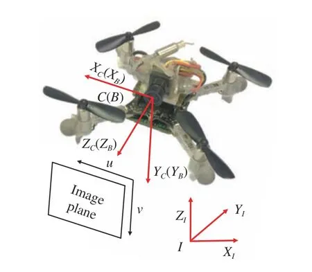
Fig.1. The developed nano-scale UAV platform. For the convenience of presentation, the body frame {B} is assumed to be coincident with the camera frame {C}. If it is not the case, these two frames can be related to a constant transformation matrix according to their relative pose.
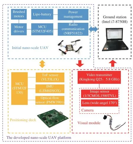
Fig.2. Hardware configuration.
The rest of this paper is organized as follows. In Section II,we give an overview of the overall system and present the hardware structure and system flow chart. Sections III and IV,respectively show the key components of the proposed tracking system: visual object tracking module and positionbased visual servoing control module. In Section V,implementation details and experimental results are presented.In addition, some main notations used in this paper are given in Table I.
II. SYSTEM OVERVIEw
In this section, we first introduce the hardware structure of the developed nano-scale UAV platform. Then, the flow chart of the proposed tracking system is presented.
A. Hardware Structure
1) Nano-Scale UAV Platform: Our UAV platform is theCrazyflie 2.02https://wiki.bitcraze.io/(Fig.1), a nano-scale quadrotor, which weighs only 27 g with a size of 92 mm ×92 mm ×29 mm (length,width, and height). Its maximum flying time is 7 minutes and maximum payload is 15 g. The on-board micro controller running the main flight control algorithm is implemented with STM32F405, and the radio communication module is implemented with NRF51822. Moreover, the core on-board sensors include a pressure sensor (LPS25H) and an inertial measurement unit (IMU, MPU9250) composed of a three-axis gyro, a three-axis accelerometer and a three-axis magnetometer. The pressure sensor and IMU sensor are disabled in our implementations due to poor measurement accuracies.Additionally, there is a flow deck consisting of a ToF (timeof-flight) sensor (VL53L0X) and an optical flow sensor(PMW3901) which are respectively responsible in measuring the vertical distance and horizontal velocity relative to the ground. However, the upper measurement limit of VL53L0X is only 2 m, therefore, this flow deck is not used in our developed platform.

TABLE I NOMENCLATURE
2) Positioning Deck: In order to provide the UAV platform with accurate pose estimation, we integrate a new positioning deck (Fig.2) (with a weight of 4.9 g and size of 28 mm ×28 mm ×2 mm) with reference to the schematics of the aforementioned flow deck. This positioning deck is composed of an MCU (micro-controller unit, STM32F130), a better quality IMU (LSM6DSOX), a new version of the ToF sensor(VL53L1X), and a new optical flow sensor (PMW3901).Compared with MPU9250, LSM6DSOX has better zero bias stability and provides more accurate acceleration and angular velocity measurements. Moreover, the upper measurement limit of VL53L1X is 4 m, twice that of VL53L0X. In addition,the extended Kalman filter algorithm is implemented on the MCU STM32F130 to fuse measurements from the IMU,optical flow sensor and ToF sensor to estimate the pose of UAV in real time [38], [39].
3) Visual Module: In order to enable the considered nanoscale UAV with the capability of object tracking, a lightweight visual module is integrated, and correspondingly,the ground station is equipped with an image acquisition card to receive image frames in real time (30 Hz). This visual module weighs only 4.7 g and includes a camera and an analogue video transmitter as shown in Fig.2. In particular,the camera consists of a complementary metal oxide semiconductor (CMOS) image sensor with an image resolution of 1500 transmission line pulsing (TVL) and a wide-angle lens with field-of-view of 60◦×95◦×125◦(vertical, horizontal, and diagonal). In order to ensure low transmission latency and sufficient communication distance,we chose the Kingkong Q25 5.8 GHz video transmitter with an image translation delay of 35– 45 ms and maximum transmission distance of 150–200 m (without occlusion).
B. System Flow Chart
The flow chart of the proposed tracking system is shown in Fig.3. First, the nano-scale quadrotor takes off from the ground. The visual object tracking module processes the received images to estimate the location of the object in the image plane. Then, the relative position between the object and the quadrotor in the inertial frame are calculated based on the visual tracking results. Finally, the adaptive tracking controller calculates the corresponding control input to track the object. In addition, if the visual object tracking module fails to track the object, the yaw angle of the quadrotor will be adjusted in time to search again the missing target. If the object fails to be found after a preset period of time, the quadrotor will land automatically for safety reasons.
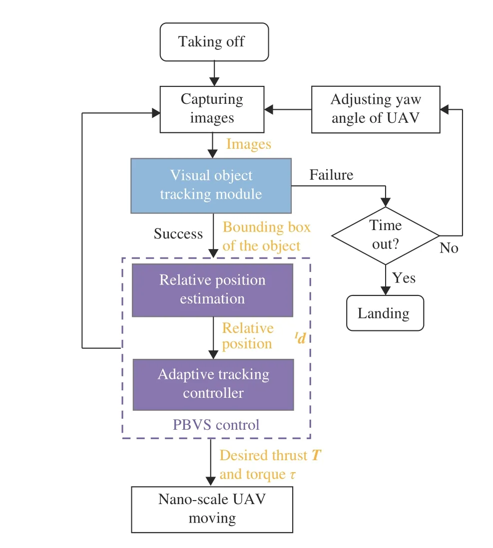
Fig.3. Flow chart of the proposed object tracking system.
As shown in Fig.3, the proposed tracking system mainly consists of two key components: the visual object tracking module (Section III) and position-based visual servoing control module (Section IV), in which the considered PBVS control is resolved into two sub-tasks: relative position estimation (Section IV-A) and adaptive tracking controller design (Section IV-B).
III. VISUAL OBJECT TRACKING MODULE
In this section, we will detail the proposed visual object tracking module, where two operation modes are included,i.e., tracking an artificial object (the concentric circles), and tracking a non-artificial object (a pedestrian).
In the object tracking problem, the considered objects are usually divided into artificial and non-artificial objects.Generally speaking, the case of artificial objects is relatively simple with obvious features (e.g., special geometry shape or color), such that one can directly leverage frame by frame detection method to achieve tracking with these simple features. In comparison, the case of non-artificial objects, e.g.,pedestrians, vehicles, and UAVs, is relatively complex since the selection and extraction of features are difficult. Therefore,for non-artificial objects, it is not possible to directly apply simple feature-based detection methods to realize stable and accurate tracking.
In this section, we first introduce an artificial object tracking algorithm based on the frame by frame detection method with concentric circles as an example. Then, we propose RMCTer,a dual-component object tracking algorithm, where the pedestrian is regarded as a tracking example of a non-artificial object. It is important to point out that the proposed RMCTer algorithm is general and can be easily applied to track other artificial or non-artificial objects.
A. Tracking an Artificial Object: The Concentric Circles
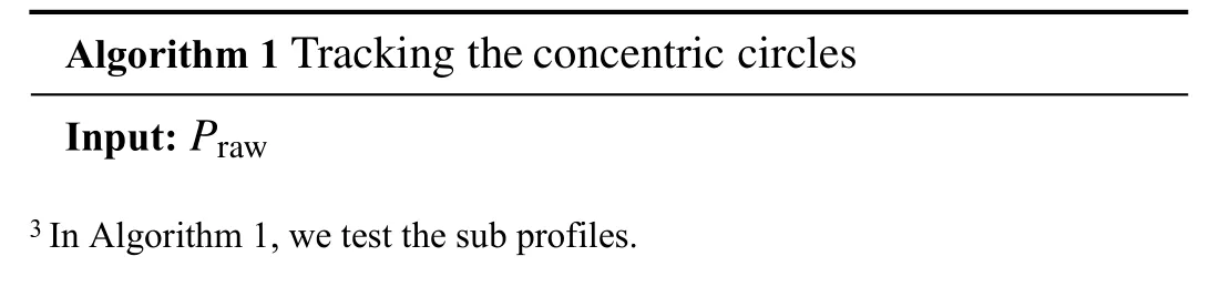
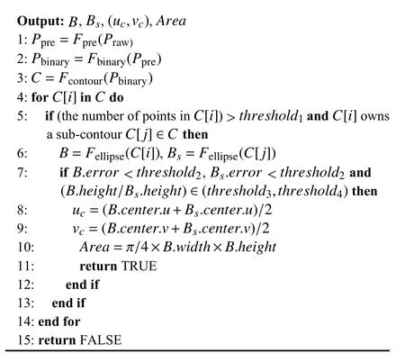
The details are described in Algorithm 1 below, where P represents a mask of the same size as the input image, F represents a function, C represents all the closed contours in the image, C[i]∈C and C[j]∈C represent the i-th and j-th closed contours which are stored in point sets, respectively, B and Bsare arrays which contain the parameters of the fitted ellipses including the coordinates of the center point, the height, the width, the angle and the fitting error. Subscripts are used to explain the meaning of variables or functions. For example, Prawis the original image, Fprerepresents the image pre-processing function, i.e., it denoises and drops corrupted frames, Fbinaryis the image binarization function, Fcontourrepresents the function of fitting closed contours, and Fellipseis the function of fitting ellipse.
During flight, the concentric circles may distort into two concentric ellipses in the image, while the height (or width)ratio of the two ellipses (B.height/Bs.height) stays invariant.In view of this fact, the target is uniquely identified.Furthermore, the coordinates of the center point ((uc,vc)) and the area of the outer circle (Area) can also be calculated.Different from [40], the inclusion relationship of the concentric circles is leveraged in the detection. In particular,we first find a closed contour, and then only test its parent or sub profiles3instead of all other closed contours in the image.In this way, the computation is simplified and the processing speed is much improved.
B. Tracking a Non-Artificial Object: A Pedestrian
In this section, we propose a robust multi-collaborative tracker (RMCTer) to achieve stable and accurate pedestrian tracking in real time. As shown in Fig.4 , the RMCTer consists of a short-term tracking module and a long-term processing module. In particular, a two-stage correlation filter-based tracker consisting of a translation filter and a scale filter is employed for the short-term tracking module. This component generally works accurately and efficiently in relatively stable scenarios. Along with this short-term module,in order to be robust against variations in the appearance of object and compensate for visual tracking errors, an efficient long-term processing module is presented. It is composed of a learning-based multi-object detection network (i.e.,YOLOv3), and a two-stage template scoring component based on the image histogram and SURF (speeded up robust features) matching. Note that, although the detection network(YOLOv3) requires a relatively large amount of computation resource, our short-term module is computationally efficient with reliable short-term tracking performance. A periodic takeover control strategy is adopted for the proposed tracker to ensure both effectiveness and real-time performance. For each N received frames, the first N −1 continuous frames are directly processed by the short-term tracking module, while the N-th frame is the input to the long-term processing module and its output is leveraged to modify the current tracking model in a timely manner. Obviously, a smaller N makes the proposed tracker more robust to visual tracking errors and object appearance changes, but excessively decreasing N leads to increasing amounts of computations and therefore affects real-time performance. According to experimental experience, we set N ∈(fi/3−fi/2) with fibeing the image frequency, after which satisfying tracking performance can be achieved. In addition, in order to observe the tracking state and determine whether to re-initialize, the shortterm tracking state and the long-term processing state are defined in terms of the peak-to-sidelobe ratio (PSR) value and the evaluation scores based on image histogram and SURF matching, respectively.

Fig.4. Overview of the proposed robust multi-collaborative tracker: RMCTer, which mainly consists of a short-term tracking module and a long-term processing module.
The following subsections detail successively all the components of RMCTer: the two-stage short-term tracking module, long-term processing module and initialization/reinitialization approach.
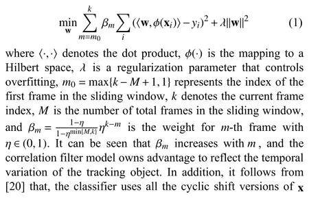
1) Two-Stage Short-Term Tracking Module: In order to obtain accurate and efficient short-term tracking performance,we leverage a correlation filter-based tracker, where a twostage filter process is performed to obtain translation estimation and scale estimation. In particular, the employed tracker is based on the KCF [20] and discriminative scale space correlation filter (DSSCF) [22]. Compared with[20]–[22] where only the current frame is used to train the discriminative model such that the temporal correlation is inevitably neglected, we use the recent frames in a sliding window to train our discriminative model. In this way, the tracking model is weighted by time order and inherently contains a temporal context, leading to a better description of the current object appearance.
For translation estimation, the goal of training is to find a classifier f(x)=〈w,ϕ(x)〉 which minimizes the squared error over samples xiand their regression targets yi
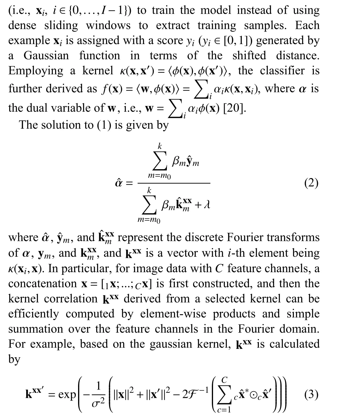
where ⊙ denotes the operator of element-wise products, and c is the index of the feature channels.
During the detection, given a candidate image patch z which is determined by the tracking result of the last frame, all cyclic p atches of z are evaluated via


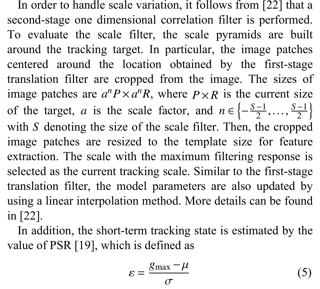
where gmaxis the maximal value on the correlation map f(z) , µand σ are the mean and standard deviation of the sidelobe.Given ε, we simply define three short-term tracking states Stbased on two predefined threshold τ1and τ2
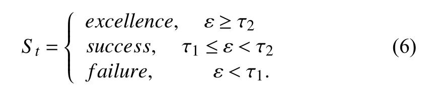
If the state is success or excellence, the current tracking model is updated in a general manner. If the state is failure,the re-initialization module starts. In addition, if the state is excellence, the current tracking patch will be selected as the template update candidates leveraged in the long-term processing module.
2) Long-Term Processing Module: As described in Section I,a single short-term tracking module cannot effectively adapt to the variations of object appearance and handle tracking errors. Therefore, we propose a long-term processing module,which is composed of a state-of-the-art deep learning-based object detection network (i.e., YOLOv3) and a two-stage template scoring component.
In particular, the input frame is first processed by the YOLOv3 network, whose output consists of multiple bounding boxes containing various objects and the corresponding labels.Then, the image patches corresponding to the bounding boxes with pedestrian labels are cropped from the image and selected as the candidate image patches. If there are no bounding boxes with the pedestrian label, this frame is directly processed by the short-term tracking module, and the next frame is input to the long-term processing module. If this condition occurs in E (E=4 in our implementation)consecutive frames, then re-initialization is started. Note that if our objective is to track other targets, the selected labels can be easily modified. Next, the two-stage template scoring component is employed to determine the unique tracking object from the candidates. In the first stage, we perform similarity testing in terms of an image histogram between the candidate image patches and template images. In the second stage, SURF matching is performed between the template images and the top three candidate image patches in similarity testing. In terms of the above two-stage results, these three candidate image patches are assigned with comprehensive evaluation scores. In particular, we denote the highest score as
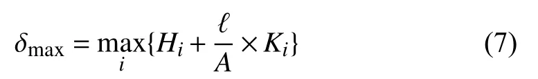
where i represents the index of the top three candidate image patches in similarity testing, Hidenotes the similarity value based on image histogram, A represents the area size of the image patch, ℓ represents an adjustable coefficient, and Kirepresents the number of matched SURF points. If δmaxis less than the predefined threshold τd, the long-term processing state is failure, and the re-initialization module is activated. If δmaxexceeds τd, the state is set to success. The corresponding image patch with δmaxis the result of long-term processing module, denoted by xl. Then, we use it to modify the current short-term tracking model. In particular, the tracking patch x is first updated according to
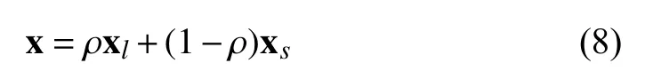
where ρ ∈[0,1] denotes the weight coefficient and xsrepresents the current tracking result from the short-term tracking component. Then, the model parameter αˆ is correspondingly updated in terms of (2), (3), and (8).
As the tracking process proceeds, the template images should be updated in real time due to possible variations in the object appearance. Therefore, we perform a fast templates updating method. In particular, the tracking patches with short-term tracking state Stbeing excellence are first selected as template candidates, and then, the candidate which has a certain parallax with the latest template image is selected as a new template. In order to guarantee the bounded computational complexity for template scoring, the total number of templates is set to 3–5 in our implementation.
3) Initialization/Re-Initialization: The initialization/reinitialization approach becomes simple thanks to the wellestablished long-term processing module. To be specific, the processing result of the long-term processing module serves as the initial bounding box of the object after the long-term processing state stays as success for L successive frames. The bounding box is then leveraged to activate the short-term tracking module.
IV. POSITION-BASED VISUAL SERVOING CONTROL
Based on the visual object tracking results (Section III), we propose a PBVS control method for a nano-scale quadrotor to achieve tracking. In this section, we first introduce a method of estimating the relative position between the object and the quadrotor. Then, a nonlinear adaptive tracking controller is proposed by taking into account the dynamics of the nanoscale quadrotor and the presence of internal and external disturbances.
A. Relative Position Estimation
In order to perform the PBVS task, the relative position between the object and the quadrotor in the inertial frame must be calculated. Therefore, we propose a feasible twostage estimation method, and the following assumptions are first imposed.
Assumption 1: The object height is relatively stable.
Assumption 2: In the initialization stage, the altitude of the quadrotor is available and the tracking object is on flat ground.
Remark 1: Assumption 1 is reasonable since most common practical tracking objects satisfy such an assumption, e.g.,rigid-body, cars, standing pedestrian. Note that Assumption 2 is only needed in the initialization stage instead of being required in the whole tracking process as considered in [9] and[28]. Therefore, Assumption 2 can be more easily guaranteed and more applicable to the practical tracking assignment (e.g.,slope ground, object moving up and moving down during tracking).
As shown in Fig.5, we denote fAand fBas the highest and lowest points of the tracking object, and A′and B′as their projection points on the image plane, respectively. In our implementation, the projection points A′and B′are determined by the midpoints of the upper bound and the lower bound of the tracking bounding box, respectively. According to the standard pinhole imaging model, the positions of fAand fBin the inertial frame are given by
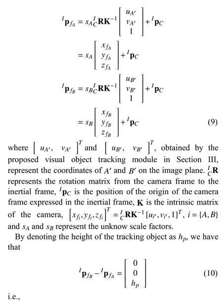
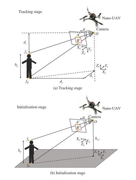
Fig.5. Illustration of relative position estimation between the object and the nano-scale quadrotor.
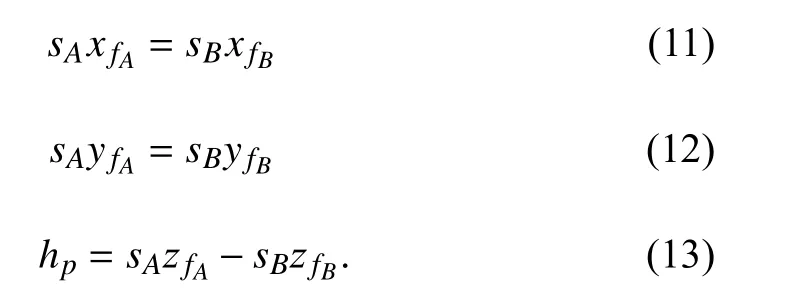
In terms of (11) and (12), we have that
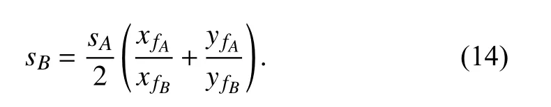
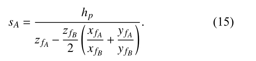
Substituting (14) into (13) yields
In the tracking stage (Fig.5(a)), the relative position between the object and the quadrotor in the inertial frame, i.e.,Id=[dx,dy,dz]T, is defined by
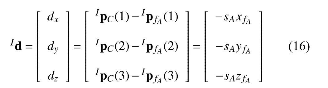
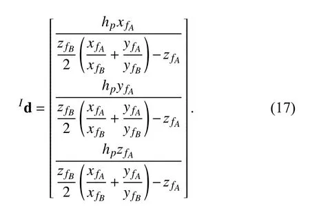
whereIpC(i) represents the i-th element of the vectorIpC.Then, substituting (15) into (16) yields
However, the value of object height cannot be directly obtained since there is no prior model information of the tracking object. We therefore design a feasible method to estimate the object height.
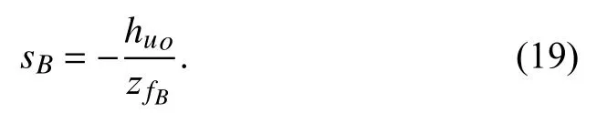
In the initialization stage, as shown in Fig.5(b), it follows from Assumption 2 that:

where huorepresents the altitude of quadrotor retrieved from fusing the datum of the altitude sensor (e.g., ToF sensor) and IMU sensor in the initialization stage. According to (18), the scale factor sBcan be calculated by
Substituting (14) and (19) into (13) yields
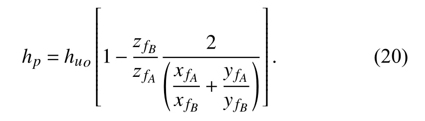
Based on (9) and (20), the height of the object hpis obtained.Therefore, for every upcoming frame in the tracking stage, it follows from Assumption 1 that the relative position between the object and the quadrotor is calculated by implementing (9)and (17) with the obtained hp.
Note that after initialization, our estimation method does not depend on the flat ground assumption and does not need the altitude information of the UAV. It is especially useful in the cases where the object moves up or moves down during tracking, or the altitude information of the UAV is not reliable(note that the upper measurement limit of ToF sensor is only 4 m).
B. Adaptive Tracking Controller
Next, we present a nonlinear adaptive tracking controller for the nano-scale quadrotor to achieve stable object tracking with consideration of the presence of internal and external disturbances.

where d denotes the distance from the quadrotor center of gravity (c.g.) to the rotation axis of each propeller, and k is the anti-torque coefficient. Since the thrust of each propeller li(i=1,2,3,4) can be evaluated with the applied thrust F and torque τ explicitly via (26), F and τ will be used for the subsequent controller development.
Assumption 3: The disturbance forces ∆f and torques ∆τ are bounded. In particular,

Assumption 4: During the flight progress, the pitch angle θ and the roll angle ϕ are both in the region (−π/2,π/2).
Remark 2: Assumption 3 is valid because the forces ∆f and torques ∆τ are always bounded in practical applications.Assumption 4 is reasonable since our nano-scale quadrotor is supposed to operate only under hovering or low velocity flight modes. Agile motions of quadrotors are beyond the scope of this research. The same assumption is also utilized in [37],[43], [44].
2) Simplified Model: Due to the strong coupling of the above quadrotor model (21)–(25), it should be decoupled to facilitate the control design. In particular, the quadrotor model can be divided into two subsystems [44]
a) Altitude system

A. Visual Object Tracking Module
As described in Section III, the proposed visual object tracking module includes two operation modes: tracking an artificial object (the concentric circles) and tracking a nonartificial object (a pedestrian).
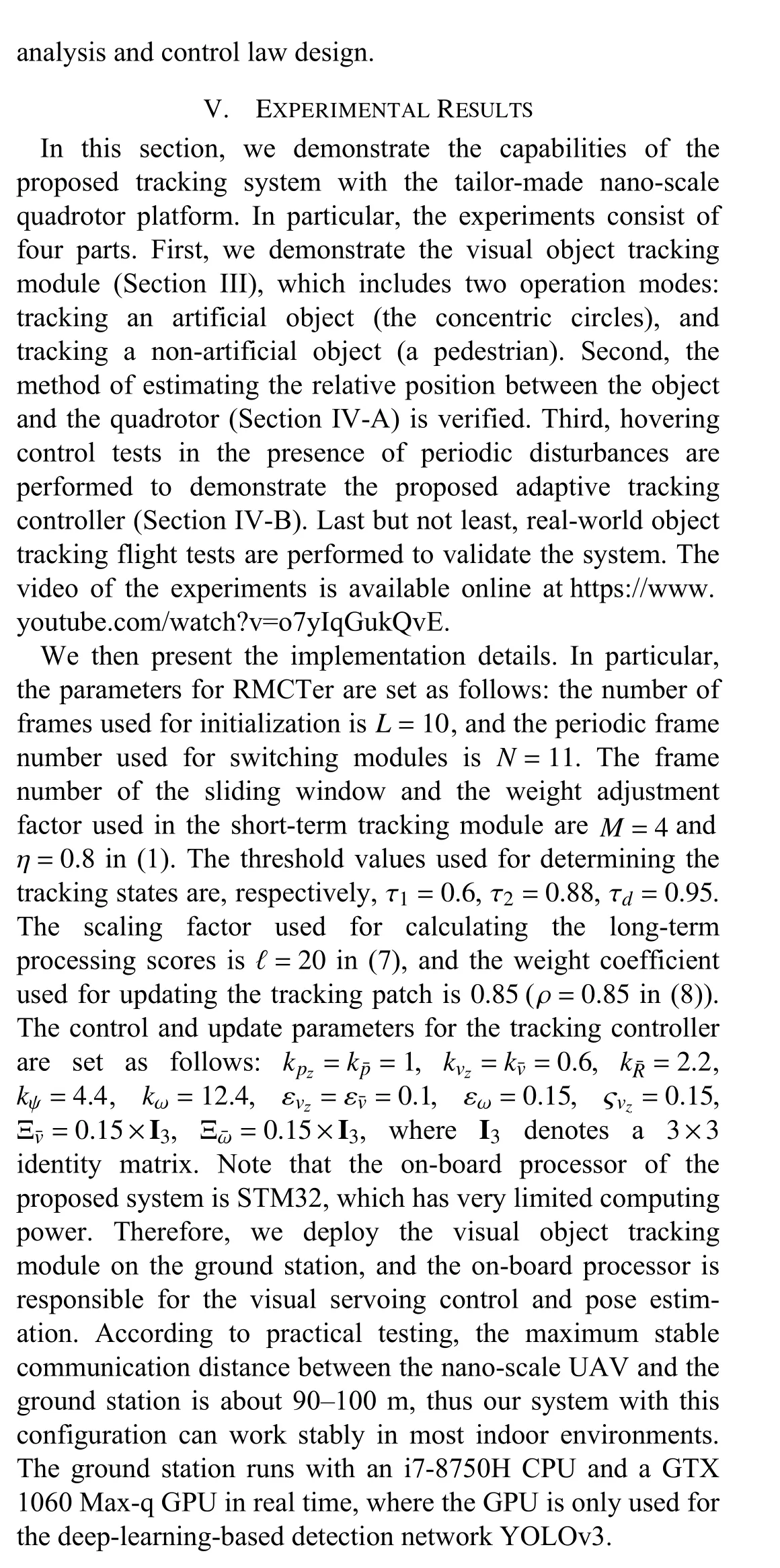
First, we compare the developed concentric circle tracking algorithm (Section III-A) with the method adopted in [40].The result is shown in Fig.6. The left image is the result by leveraging the method of [40], and the right image shows the result by performing the proposed algorithm. The time consumptions of algorithms are marked with yellow text in the lower left corner of the images. It can be seen that,although these two methods both successfully identify the concentric circles, the proposed algorithm uses less time due to the use of the inclusion relationship of concentric circles.
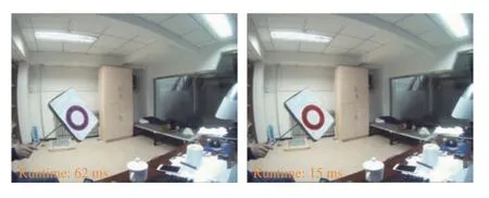
Fig.6. The result of concentric circle tracking.
Next, we validate the capabilities of the proposed tracking algorithm RMCTer (Section III-B) on public datasets and in real-world environment. We conduct the evaluation on the popular benchmark proposed by [47], which contains 100 fully annotated sequences. For the comparison tracking algorithms, we consider several state-of-the-art approaches including the well-known long-term tracker TLD,discriminative tracker Struck, and correlation filter-based trackers CSK [21], KCF, and discriminative scale space tracker (DSST) [22]. The comparison results on the representative videos/frames are shown in Fig.7. If a tracker is missing, there is no tracking bounding box drawn in the corresponding frame. In particular, we focus on testing the datasets with tracking objects being pedestrians or vehicles because they are included in the detection categories of YOLOv3 (used in the long-term processing module of our tracker). It can be seen that RMCTer exhibits better robustness and accuracy compared with the aforementioned tracking algorithms. In particular, the bounding box of RMCTer tightly encloses the tracking object in all frames, while other trackers do not consistently resize the bounding boxes when the scale or shape of the object changes and even fail in several cases due to occlusion, objects out-of-view and deformation of objects. For our real-world experiment, we collect two challenging datasets denoted as dataset_1 and dataset_2,where dataset_1 is collected in the bright environment and dataset_2 is collected in low light. In addition, both two datasets also reflect other challenges in visual tracking including objects with scale variation, occlusion, deformation,out-of-plane rotation and out-of-view. For our evaluation,RMCTer is compared with state-of-the-art tracking algorithms, i.e., DSST, KCF, and CSK. Also, we compare the proposed algorithm with the detection network YOLOv3 adopted in the long-term processing module, so as to further demonstrate the efficiency of the proposed tracker. Note that manual initialization is required when performing the above tracking algorithms. This means that we need to manually draw a bounding box that tightly contains the object. In contrast, our method does not require this manual initialization thanks to the proposed automatic initialization mechanism. The experimental results are shown in Fig.8.Firstly, we can see that RMCTer exhibits much better robustness and accuracy compared with other trackers. In particular, the proposed algorithm tracks the target accurately in all frames, and successfully deals with object disappearance(7th frame in dataset_1 and 5th frame in dataset_2), poor illumination (dataset_2) and occlusion (3rd frame in dataset_1 and 8th frame in dataset_2). On the other hand, KCF, CSK,and DSST may fail to track the object and cannot be restored due to these factors. Secondly, compared with other object detection algorithms, i.e., YOLOv3, the RMCTer are computationally more efficient with comparable accuracy. To be specific, the average speed of the RMCTer achieves approximately 60/63 FPS in dataset_1/dataset_2, while YOLOv3 achieves only 10/12 FPS under the same parameter configuration (both are implemented by Python). In addition,from Fig.8(b), we can also see that YOLOv3 is a multi-target detection network, and therefore cannot distinguish the specific object from the candidates belonging to the same category.
B. Relative Position Estimation
In order to evaluate the accuracy of relative position estimation introduced in Section IV-A, we conduct two indoor experiments, where the object is fixed and we manually control the quadrotor moving to change the relative position between the object and the quadrotor in real time. Meanwhile,an OptiTrack4http://www.optitrack.com/motion capture system in Fig.9 is used to record the three-dimensional positions of the object and the quadrotor to obtain the groundtruth of relative position. The experimental results are shown in Figs. 10 and 11. In particular, Fig.10 shows the comparison between the estimated and groundtruth of the relative position between the nanoscale quadrotor and the concentric circles, and Fig.11 shows the comparison between the quadrotor and the pedestrian. It can be seen that the estimated results achieve good accuracy.In particular, corresponding to Fig.10, the estimation errors are respectively 2.52 cm, 1.17 cm, and 2.17 cm for X-axis, Yaxis, and Z -axis. In addition, for Fig.11 , the errors are respectively 2.74 cm, 4.49 cm, and 2.53 cm.
C. Adaptive Hovering Control
In order to verify the proposed tracking controller (Section IV-B), adaptive hovering control experiment is performed.The control objective is to let the nano-scale quadrotor hovering at the original point even under a periodic disturbance. The desired horizontal position is set to be x=0 m,y=0 m, and the desired altitude is set to be z=0.55 m. The external disturbance is applied in the vertical direction, and its amplitude and the frequency are 0.1 N and 1 Hz, respectively.Therefore, we mainly observe the altitude change of the nanoscale UAV in this experiment. For purposes of comparison,triple cascaded PID controllers consisting of an outer-loop position subsystem, and inner-loop attitude and angular rate subsystems are also implemented on this nano-scale quadrotor platform. The OptiTrack system is used to record the altitude value of the quadrotor. Fig.12 illustrates the comparison of altitude variation between the proposed controller and the cascaded PID controllers. It can be seen that both algorithms achieve hovering with bounded tracking errors. However, the hovering error with the proposed adaptive mechanism is much smaller than the one with cascaded PID mechanism. In particular, the average error decreases from 4.24 cm to 1.69 cm,and the maximum error decreases from 9.44 cm to 5.05 cm.The result indicates that the proposed adaptive control design exhibits good robustness to the disturbances and achieves better control performance than the PID controller does.
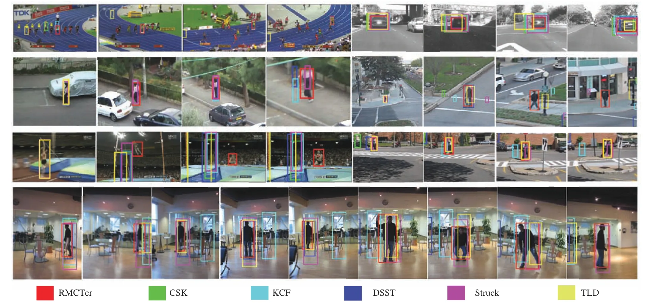
Fig.7. Tracking results for the proposed tracking algorithm in representative videos/frames on the public datasets. The illustrative examples are from sequences Bolt, Car4, Woman, Human6, Couple, Jump, and Human2.

Fig.8. Single pedestrian tracking in real environment. In dataset_1, the tracking object is the right pedestrian of the first frame; in dataset 2, the tracking target is the left pedestrian of the first frame.
Fig.9. The OptiTrack motion capture system.
D. Adaptive Visual Object Tracking
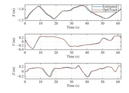
Fig.10. Relative position estimation between the nano-scale quadrotor and the concentric circles.

Fig.11. Relative position estimation between the nano-scale quadrotor and the pedestrian.
To demonstrate the whole proposed tracking system, realworld object tracking flight tests are performed. In the experiment, the tracking object moves randomly in threedimensional space, and the disturbance is the same as the one for the hovering control test (Section V-C). The threedimensional positions of the object and the quadrotor are recorded by the OptiTrack system. Figs. 13 and 14 show the tracking performance of concentric circle tracking and single pedestrian tracking, respectively. It can be seen that the trajectories of the nano-scale quadrotor are consistent with those of different objects. In particular, in Fig.13, the average tracking errors are 6.78 cm, 8.65 cm, and 5.19 cm,respectively for the X, Y, and Z axes, and in Fig.14, the average tracking errors are 4.84 cm, 9.48 cm, and 7.06 cm.The results indicate that the proposed visual object tracking algorithm and position-based visual servoing control algorithm are effective, and can be implemented on the developed nano-scale quadrotor platform to achieve stable,accurate and real-time object tracking in the presence of disturbances.
VI. CONCLUSION
In this paper, we propose a monocular vision-based object tracking and servoing control system using a tailor-made nano-scale UAV platform. In order to guarantee tracking robustness and accuracy, we propose a novel visual object tracking algorithm, i.e., RMCTer, where a powerful shortterm tracking module and an efficient long-term processingmodule are tightly integrated. Moreover, an adaptive PBVS control method is proposed to achieve stable and accurate object tracking in the presence of internal and external disturbances. The experimental results demonstrate that each component of the proposed system is effective, and that the whole tracking system has high accuracy, strong stability, and low latency. An interesting direction for further work is the realization of a lightweight and robust state estimation algorithm (i.e., visual-inertial odometry or simultaneous localization and mapping) on the nano-scale UAV platform,such that stable object tracking can be obtained in more complex and more challenging environment.
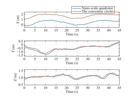
Fig.13. Real-world flight experiment of concentric circle tracking in the presence of disturbance.
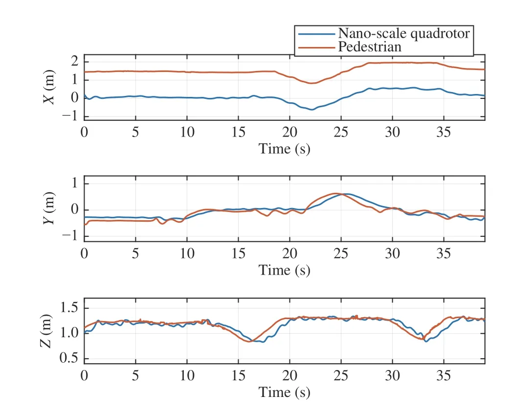
Fig.14. Real-world flight experiment of single pedestrian tracking in the presence of disturbance.
杂志排行

IEEE/CAA Journal of Automatica Sinica的其它文章
- Digital Twin for Human-Robot Interactive Welding and Welder Behavior Analysis
- Dependent Randomization in Parallel Binary Decision Fusion
- Physical Safety and Cyber Security Analysis of Multi-Agent Systems:A Survey of Recent Advances
- A Survey of Evolutionary Algorithms for Multi-Objective Optimization Problems With Irregular Pareto Fronts
- A Survey on Smart Agriculture: Development Modes, Technologies, and Security and Privacy Challenges
- Multiagent Reinforcement Learning:Rollout and Policy Iteration