Interrogation technology for quasi-distributed optical fiber sensing systems based on microwave photonics
2021-04-20WUNishanXIALi
WU Ni-shan,XIA Li
(School of Optical and Electronic Information, Huazhong University of Science and Technology, Wuhan 430074, China)
Abstract:Quasi-distributed fiber sensing systems play an important role in the fields of civil engineering,energy surveying,aerospace,national defense,chemicals,etc.Interrogation technology for quasi-distributed fiber sensing systems based on microwave photonics is widely used in high-speed and high-precision signal demodulation and sensor positioning in optical fiber multiplexing systems.Compared to conventional optical wavelength interrogation,this technology greatly improves system demodulation rate and compensates for the defects of traditional sensor positioning methods.This paper introduces the recent research progress of quasi-distributed fiber sensing interrogation technology based on microwave photonics;compares and analyzes the advantages and disadvantages of several existing microwave demodulation systems from the perspective of their fiber grating quasi-distributed sensing and fiber Fabry-Perot quasi-distributed sensing systems,respectively;and provides a summary of the prospective direction of future research in quasi-distributed fiber sensing interrogation technology based on microwave photonics.
Key words:radiofrequency photonics;quasi-distributed sensing;fiber sensing interrogation;fiber bragg gratings;fiber Fabry-Pérot
1 Introduction
With the advent of high-speed information era,the Internet of Things has gradually become an important scientific and technological basis for human beings to obtain external information,predict environmental changes,and improve the quality of production and life.As an indispensable key component of detection system,Optical Fiber Sensor(OFS)has been widely applied in civil engineering,biology,chemical industry,mechanics,electrics,aerospace and other fields owing to its advantages such as small size,light weight,high accuracy,corrosion resistance,resistance to electromagnetic interference,low cost,and good compatibility with the existing optical fiber communication system[1-2].
By networking,arranging and multiplexing discrete OFS units,the physical quantities such as temperature,strain and vibration can be sensed and measured in a long distance.Different from the fully distributed sensing system based on Rayleigh,Raman or Brillouin scattering effect,this quasi-distributed fiber sensing system does not need to stimulate the nonlinear effect in optical fiber,and can easily establish the quantitative relationship between the sensing optical signal and the parameter to be measured.It can flexibly design the system performance parameters such as covered distance and measurement accuracy in accordance with actual requirements,to help control and reduce the system construction cost.Meanwhile,it can detect more diverse changes in refractive index,curvature and other external factors,and can measure dynamic events.Therefore,quasi-distributed optical fiber sensing system has played an important role in oil well exploration,early fire warning,and monitoring the structural health of large buildings[3-6].
Depending on the type of multiplexed fiber sensor,quasi-distributed fiber sensing systems can be roughly divided into Fiber Bragg Grating(FBG)quasi-distributed sensing system and fiber Fabry-Pérot(FP)quasi-distributed sensing system.The FBG quasi-distributed sensing system takes the wavelength modulation sensor FBG as the sensing unit.By using the phase mask,UV irradiation and other methods,the refractive index of fiber core is periodically changed to reflect the light satisfying the Bragg wavelength.When the environmental change causes the thermo-optic or elastic-optic effect in the fiber,the central wavelength of the grating will change so that the parameter to be measured can be sensed[7-10].On the other hand,the fiber FP quasi-distributed sensing system takes the fiber phase modulation sensor FP structure as the sensing unit.At first,a reflector is formed in the fiber structure through welding,corrosion,film coating,laser micro-processing and other methods.Then,the phenomenon that the two-beam interference spectrum between reflectors is modulated by external physical quantities is utilized to detect the target parameter[11-12].
While the quasi-distributed fiber sensing system is widely used in many fields,the increasing application demand is raising higher requirements for the construction and maintenance cost,multiplexing capacity,coverage,measurement rate and localization ability of this system and urging researchers to ceaselessly explore new sensing demodulation techniques.In recent years,with the rapid development of microwave photonics,this new interdiscipline with the advantages of photonic and microwave techniques(such as large bandwidth,low loss,flexibility and reconfigurability[13-15])has been extensively researched in Radio over Fiber(ROF),space exploration,radar system and other fields[16-18],while showing attractive application potential in the field of fiber sensing demodulation.By modulating microwave signals to optical signals through microwave photonics technique and adopting the means of microwave measurement,the demodulation rate of the system can be improved,high measurement accuracy and strong localization ability can be secured,and the construction and maintenance cost of the system can be reduced to a certain extent.
Focusing on the application of microwave photonics in quasi-distributed fiber sensing demodulation,this paper presents the basic principle,experimental implementation and demodulation performance of microwave demodulation systems(including FBG quasi-distributed sensing system and fiber FP quasi-distributed sensing system),and finally analyzes and discusses the problems in the existing scheme and the future research direction.
2 Microwave photonic demodulation technique of FBG quasi-distributed sensing system
The basic principle of demodulating a FBG quasi-distributed sensing system with microwave photon technique is to convert the wavelength change of the sensing grating into the intensity or frequency change in the microwave domain through optical carrier modulation,to improve the demodulation precision and rate of the system by means of microwave detection,and to locate the sensing unit through time-frequency transformation.Based on the basic principle of demodulation system,the microwave demodulation solutions adopted in FBG quasi-distributed system can be broadly divided into Microwave Photonic Filter(MPF),microwave photon heterodyne,and optoelectronic oscillator(OEO).
2.1 Microwave demodulation of FBG quasi-distributed system based on MPF
The basic structure of the FBG quasi-distributed sensing demodulation system based on MPF is shown in Fig.1.The optical signal output by light source is firstly modulated with the input microwave signal through an Electronic Optic Modulator(EOM),and then is transmitted as a carrier in the optical fiber sensing system,and finally arrives at the photodetector(PD)after passing through the sensing area.At last,the output microwave signal carrying the information of parameter variation is obtained.
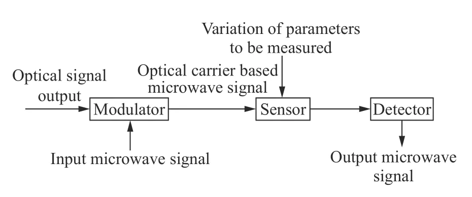
Fig.1 Diagram of FBG quasi-distributed sensing demodulation system based on MPF图1 基于MPF 的光纤光栅准分布式传感解调系统示意图
If the frequency of the input microwave signal isω,the total time for the optical signal traveling from the modulator through thei-th grating in the sensing area(where the signal is reflected)to the detector isti,the central wavelength of thei-th grating isλi,the power of the light reflected by thei-th grating isPi,and the total number of gratings in the sensing area isN,then the frequency response of the entire quasi-distributed grating sensing network can be expressed as:

Through the Inversed Fast Fourier Transform(IFFT)of the frequency response,the time-domain response of the system can be obtained:

As can be seen from the above equation,the signals reflected by different gratings present discrete impulse peaks in the time domain,and the intensity of impulse peaks contains the information on the power of the light reflected by gratings.Therefore,by detecting the microwave signal output from the sensing system,the grating sensing system can be demodulated and located.
As the input microwave signal modulated on optical carrier and the output signal obtained from photoelectric detector are required to be synchronously scanned according to the above principle in the actual demodulation process,the Vector Network Analyzer(VNA)commonly used in microwave system can fully meet the requirements of synchronous scanning.The MPF microwave demodulation system with VNA as the core is shown in Fig.2.This concept is simple in structure and easy to build,so it is widely used for the demodulation of quasi-distributed fiber sensing system[19-23].
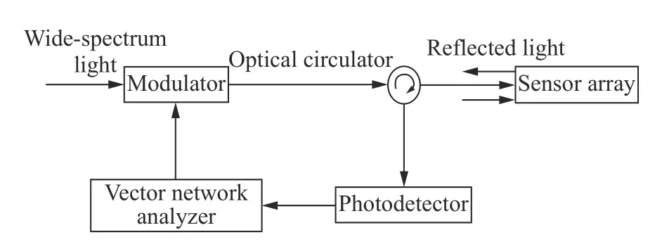
Fig.2 Diagram of MPF FBG quasi-distributed sensing demodulation system based on VNA图2 基于矢量网络分析仪的MPF 光纤光栅准分布式传感解调系统示意图
In 2013,Ricchiutiet al.from the Polytechnic University of Valencia in Spain used VNA to demodulate 500 cascaded long-period FBG quasi-distributed systems[20]for the first time on the basis of the previous demodulation experiment of a single long-period FBG sensing system[19].However,since long-period grating was a transmission-type OFS,a reflection facet and a reference tap should be added to the cascade system to improve the light reflectivity in the sensing area.As a result,the complexity and difficulty of the system were increased.
To adapt microwave demodulation system to the requirements of actual FBG sensing network better,HUST Professor Xia Li’s research group proposed a new concept(shown in Fig.3)applicable to large-scale long-distance sensing in 2015[21].In this system,identical weak inverse gratings with the same central wavelength were used as the sensing unit to improve the multiplexing capability of the system.An Optical BandPass Filter(OBPF)was used for matched filtering to convert the variation in the central wavelength of gratings into the variation in reflected light intensity so as to demodulate the specific information of each grating.When an external stress is applied to a grating,the amplitude of IFFT peak corresponding to the grating will change.The demodulation result obtained by this concept shows good linearity and good compatibility with the existing FBG sensing network.

Fig.3 Weak-reflection FBG quasi-distributed sensing demodulation system based on MPF[21]图3 基于MPF 的弱反光纤光栅准分布式传感解调系统[21]
As the MPF-based quasi-distributed grating microwave demodulation system is based on intensity demodulation,the fluctuation in the output power of light source or the losses(such as bending and winding)in the fiber sensing link will have a negative impact on the accuracy of demodulation results.To solve this problem,Chenget al.proposed a demodulation concept for quasi-distributed ultrashort FBG that combined differential filtering with microwave network[24].As shown in Fig.4,a pair of Gaussian filters with the central-wavelength difference of only 0.4 nm are set up on the upper and lower circuits of Mach-Zehnder interferometer,and the optical path difference between the two arms is used to convert the optical signal reflected by a grating into a pair of adjacent impulse signals.By calculating the intensity ratio of the two adjacent impulse peaks,the wavelength drift of the grating can be obtained.The demodulation result of this concept is immune to not only the power fluctuations of the light source but also the bending loss in the transmission fiber.
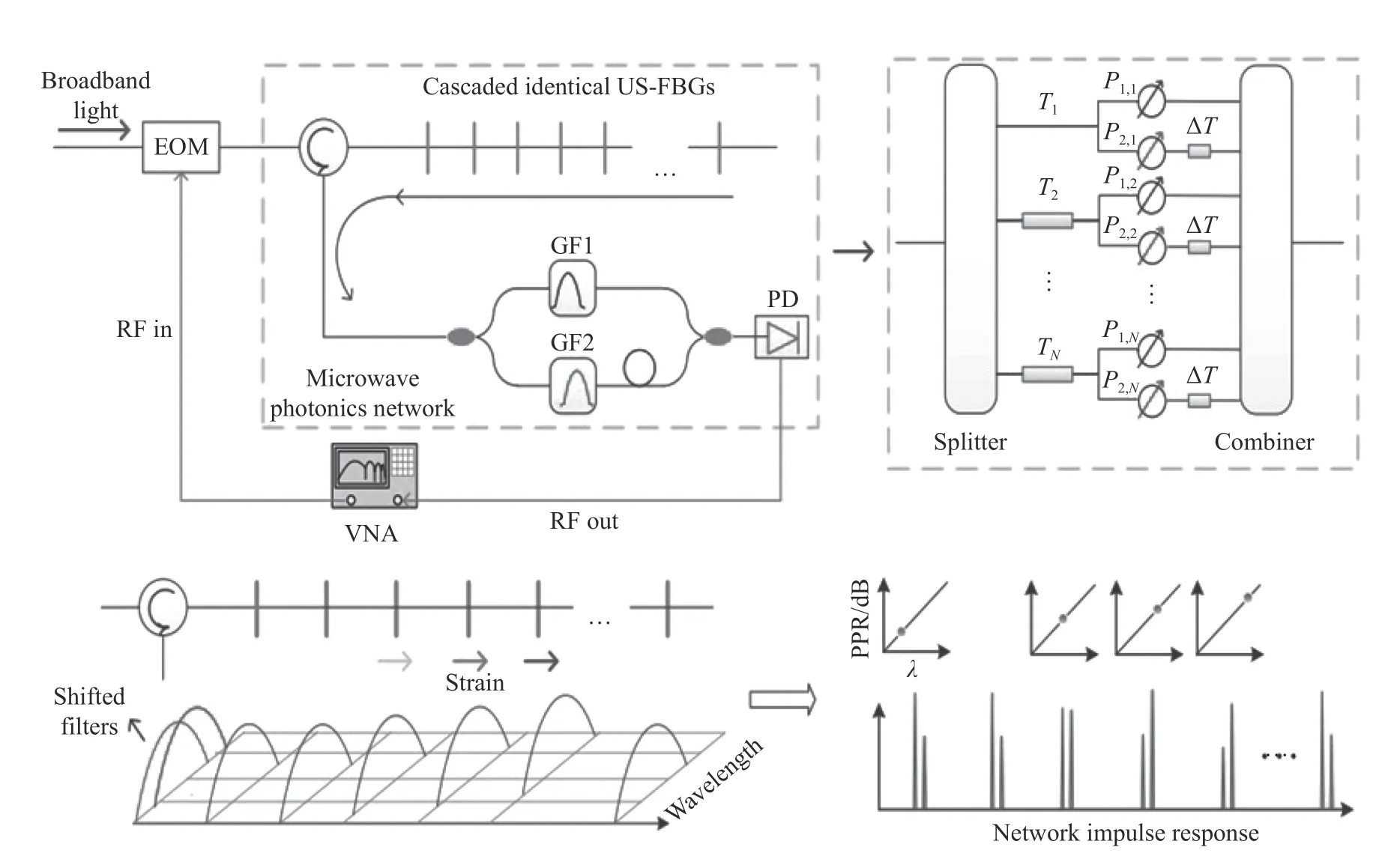
Fig.4 Basic structure and principle of ultra-short-FBG differential demodulation system based on multi-tap MPF[24]图4 基于多抽头MPF 的超短光栅差分解调系统及其基本原理示意图[24]
Although the above-mentioned microwave demodulation concepts have strong localization ability,high measurement accuracy and other advantages,they are only applicable to identical FBG network rather than a Wavelength Division Multiplexing(WDM)system composed of the gratings with different central wavelengths.To solve this problem,the researchers firstly proposed a solution of wavelength-RF delay mapping,introducing different time delays to the reflected light with different wavelengths through fiber dispersion to finally achieve the goal of distinguishing the sensing information of different gratings[25-26].However,the system raised the requirements for the length and type of the fiber to which the time delay was introduced and for the sweep range and sampling number of VNA.Moreover,the system was susceptible to the cross sensitivity of sensors.
To minimize the error of demodulation result caused by the cross sensitivity of sensors and by the optical power fluctuation and transmission loss in optical fiber link,Wuet al.proposed the use of dual Sagnac loop to realize the simultaneous differential demodulation of WDM grating multiplexing system in 2019[27].As shown in Fig.5,a Sagnac filter based on“single-mode-polarization-maintaining-singlemode”is set up on either arm of the Mach-Zehnder interferometer,and the spectra of the two filters are misaligned by 0.48 nm.Since Sagnac loop is a wide-spectrum filter with Gaussian-like transmission spectrum in each channel,the simultaneous independent linear demodulation of multiple different gratings can be achieved through the one-to-one correspondence between the central wavelengths of different FBGs and the different channels of Sagnac transmission spectra.
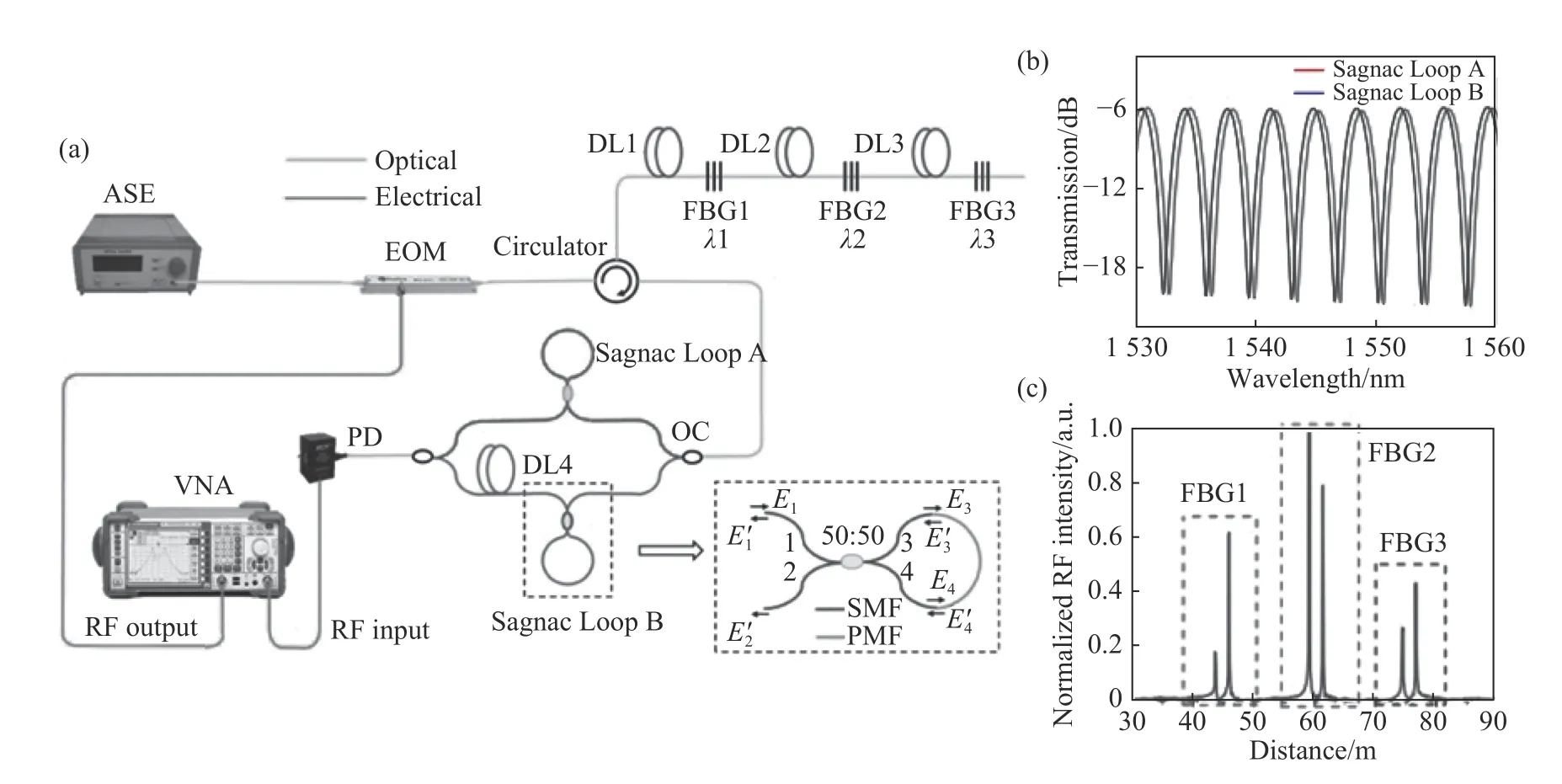
Fig.5 WDM quasi-distributed sensing microwave demodulation system based on double Sagnac loops and differential filtering.(a)System structure diagram;(b)Spectra of double Sagnac loops;(c)Time-domain response spectrum obtained from frequency response IFFT[27]图5 基于双Sagnac 环和差分滤波的WDM 准分布式传感微波解调系统。(a)系统结构示意图;(b)双Sagnac 环光谱图;(c)由频域响应逆傅里叶变换得到的时域响应谱[27]。
2.2 Microwave demodulation of FBG quasi-distributed system based on microwave photonic heterodyne
The FBG quasi-distributed microwave demodulation system based on microwave photon heterodyne also adopts the method of external modulation.That is to say,the microwave signal at high sweep frequency is loaded into the incoherent broadband light source.By detecting the heterodyne beat signal between grating reflection signal and original optical signal,the change of external environment applied to the grating is demodulated[28].In this process,the frequency change of beat signal is proportional to the change of grating wavelength and the total intra-fiber dispersion.
Based on the above principle,the researchers proposed diverse FBG microwave demodulation concepts,and obtained excellent demodulation accuracy and response rate[29-31].In 2018,Li Zhengying,a Professor in Wuhan University of Technology,and his research group combined microwave photonics with dispersion to build a quasi-distributed FBG microwave demodulation system based on microwave photon heterodyne(see the Fig.6),and realized the high-speed demodulation of weakreflection quasi-distributed FBG system[32].In this system,a 14.7 km Dispersion Compensation Fiber(DCF)was used to provide high dispersion for wavelength-frequency conversion.Eventually,high demodulation accuracy(8 pm)was achieved,and the demodulation result was highly consistent with the direct measurement result given by spectrometer.In addition,the system demonstrated an excellent dynamic sensing capability,achieving a demodulation rate of 40 kHz in high-speed vibration experiment.
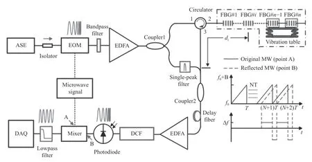
Fig.6 Microwave photon heterodyne quasi-distributed grating demodulation system based on DCF[32]图6 基于DCF 的微波光子外差准分布式光栅解调系统[32]
Although the above system has the advantages of high demodulation rate and high measurement accuracy,the thermo-optic effect and high-temperature ductility of dispersion compensation fiber at the varying environment temperature will seriously affect the beat frequency of the two optical signals,introduce an error to the demodulation result of grating wavelength and reduce the credibility of demodulation result during large-scale multiplexing.To solve this problem,Lianget al.in the research group proposed an improved concept based on DCF-SMF(Dispersion Compensation Fiber-Single Mode Fiber)dual channel in 2019[33].In the new concept,another 15.2 km SMF channel was added to the aforementioned system to eliminate the measurement error caused by environmental temperature drift and correct the demodulation wavelength value.While inheriting the advantages of singlechannel system such as high speed and low cost,the dual-channel system improves the accuracy and linearity of wavelength measurement results and eliminates the negative effect of temperature cross-sensitivity.
In addition to setting the reference link and utilizing the dispersion characteristics of DCF to realize the demodulation based on microwave photon heterodyne,the reflection technique of incoherent optical frequency domain based on chaotic source can also be used to realize the beat demodulation of quasi-distributed grating system[34-35].As shown in Fig.7,the incoherent light of the system is produced by DFB(distributed-feedback)laser,which generates chaotic oscillations under the action of optical feedback.This chaotic light source has the advantages of large line width,short coherence length and low interference noise,which can help improve the overall multiplexing capacity of the sensing demodulation network.This system experiment realized the localization and wavelength demodulation of 3 640 weak-reflection gratings,demonstrating an excellent demodulation capability of the IOFDR(Incoherent Optical Fourier-Domain Reflectometry)technique based on chaotic source in large-scale intensive multiplexing scenes.However,when demodulating the grating wavelength,the DFB laser needs to be thermo-tuned to change the wavelength of its laser beam.As a result,the demodulation speed of the system is significantly reduced and its application potential in dynamic parameter sensing is limited.
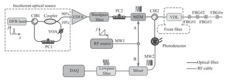
Fig.7 Schematic diagram of ultra-weak FBG quasi-distributed sensing demodulation system based on chaos source IOFDR[35]图7 基于混沌源IOFDR 的超弱光纤光栅准分布式传感解调系统示意图[35]
2.3 Microwave demodulation of FBG quasi-distributed system based on OEO
The FBG quasi-distributed microwave demodulation system based on optoelectronic oscillator(OEO)is built on the photoelectric-hybrid feedback loop structure shown in Fig.8.The modulated input optical signal is optically amplified and transmitted into the optical delay line and then converted by detector into an electrical signal.Most of the electrically amplified signals are input as feedback microwave signals to the modulator port,while the rest are output as the microwave signals for spectrum measurement.The OEO system will oscillate only when the closed-loop gain is large enough.As the oscillation frequency of OEO system mainly depends on the loop length,the key parameters such as the length of fiber ring cavity can be determined by measuring the output microwave spectrum[36-38].

Fig.8 Basic structure of OEO system图8 OEO 系统基本结构示意图
In 2020,Wanget al.from Nanjing University proposed a quasi-distributed FBG microwave sensing demodulation system based on the principle of OEO system[39].In this concept,the cascaded grating array is connected to the OEO oscillation loop through a circulator.By using the reflection characteristics of a grating,each grating in the multiplexing system is corresponding to a different loop length.By measuring and analyzing the oscillation peaks with different Free Spectral Ranges(FSRs),the information on the wavelength and spatial position of each grating can be demodulated.As a digital discrete location coding system,this system is strongly immune to interference.However,the theoretical multiplexing capacity of this concept is only 62,which still needs to be further improved in order to meet practical application requirements.
The above three different FBG quasi-distributed microwave demodulation concepts are compared in Table 1.It can be seen that the microwave demodulation concept based on MPF is more advantageous in high-precision spatial positioning.In addition,through the optimization methods such as wavelength-frequency delay mapping and differential filtering demodulation,the influence of power fluctuation on the accuracy of demodulation results can be eliminated and the demodulation requirements of WDM system can be met.However,due to the limitation of VNA scanning rate,the demodulation speed in the first concept still needs to be improved.In contrast,the demodulation concept based on microwave photon heterodyne has a much faster demodulation rate that can meet the requirements of high-speed demodulation and dynamic sensing.Its dual-channel balanced detection structure can also solve the problem of cross-sensitivity very well.However,its spatial resolution is sacrificed to some extent.The OEO-based demodulation concept has an excellent signal-to-noise ratio and stability,but its system capacity is relatively limited.Therefore,it is not suitable for the demodulation of a large-scale grating multiplexing system for the time being.
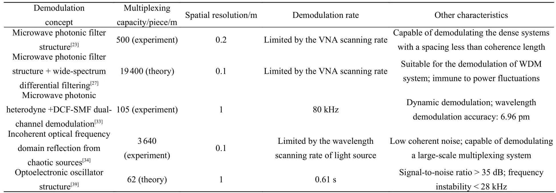
Tab.1 Comparison of different microwave demodulation concepts for FBG quasi-distributed system表 1 针对光栅光纤准分布式系统的不同微波解调方案比较
3 Microwave photonic demodulation technique of fiber FP quasi-distributed sensing system
The fiber interference structure represented by FP is another common sensing unit in the quasi-distributed fiber sensing network.Similar to the principle of FBG microwave demodulation,the optical carrier based microwave signal can also be used for auxiliary frequency domain measurement in the quasi-distributed sensing system based on fiber FP interferometer.Depending on the specific demodulation method,the microwave demodulation concepts of fiber FP quasi-distributed systems can be divided into Optical Carrier based Microwave Interferometry(OCMI)and Coherent Microwave-Photonic Interferometry(CMPI).
3.1 Microwave demodulation of fiber FP quasidistributed system based on OCMI
OCMI microwave demodulation technique is mainly based on low-coherence light source.When the light source in the system is incoherent,its coherence length will be short and its bandwidth will be far less than the optical path difference between any two reflection points.At this time,the cross product term of the responses in the complex frequency domain of the system is zero.The selfproduct term can be used to reconstruct the interference spectrum in the microwave domain,where the microwave phase shift can be used to calculate the change of optical path difference[40,44].
The above fiber quasi-distributed demodulation method using low coherence light and microwave photonics has been widely concerned by researchers since it was proposed[40-43].In 2013,the fiber FP quasi-distributed sensing demodulation concept based on OCMI was first experimentally implemented by the Xiao Research Group of Clemson University in the United States[40].As shown in Fig.9,the all-fiber FP cavity formed by single mode fiber and capillary tube through fusion is used as the cascaded sensing unit.By adjusting the central wavelength of tunable filter,the intensity of IFFT impulse signal in time domain under different wavelengths can be determined,and then the spectral information of each fiber FP can be recovered.The experimental results show that the spectrum obtained by microwave reconstruction is consistent with the direct measurement result on spectrometer.Therefore,the system has not only high accuracy but also the ability of sensor localization.
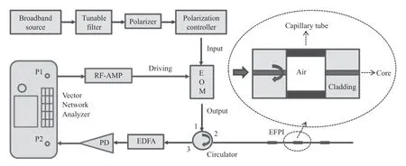
Fig.9 Fiber FP quasi-distributed sensing demodulation system based on OCMI technique[38]图9 基于OCMI 技术的光纤FP 准分布式传感解调系统[38]
The OCMI technology can demodulate the fiber FP sensing system with spatial continuity,in addition to the quasi-distributed sensing link composed of cascaded discrete fiber FP sensors.By means of hot fusion[39]or femtosecond laser inscription[41-42],a series of reflection points can be formed in the sensing fiber.Two adjacent weak-reflection points can be regarded as a pair of fiber FP structures.This FP quasi-distributed system has no dark measurement zone and applies to the measurement and monitoring of mechanical-structure surface deformation and other scenes.In addition,the OCMI technique can be applied to other types of waveguides or free-space interferometer systems,as well as the quasi-distributed measurement in a variety of physical,chemical and biological fields.
3.2 Microwave demodulation of fiber FP quasidistributed system based on CMPI
Different from OCMI technique,CMPI microwave demodulation technique is based on coherent light source.For a fiber withNweak-reflection points,when the light source is coherent light,the intensity of reflected light at the corresponding reflection points will be closely related to the change of optical path difference between reflection points due to the interference between adjacent reflection points.Therefore,the CMPI system can effectively convert the change of optical path difference between reflection points into the change of the intensity of time-domain pulses corresponding to specific reflection points.In 2017,Huaet al.built the CMPI microwave sensing demodulation system as shown in Fig.10,and verified the conclusions of their theoretical analysis through experiments[44].The experimental results showed that the system achieved a strain resolution of 0.6μεfor the fiber FPI with a cavity length of 1.5 cm.When the cavity length of FPI was increased to more than 1 m,the strain resolution could be further improved to the nε level.
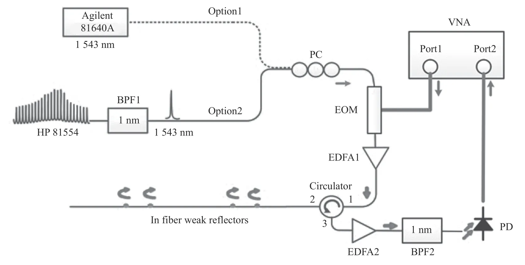
Fig.10 Fiber FP quasi-distributed sensing demodulation system based on CMPI technique[44]图10 基于CMPI 技术的光纤FP 准分布式传感解调系统示意图[44]
Due to the sensitivity of CMPI technique to the optical path difference of reflection points,this demodulation method also shows excellent performance in the measurement of dynamic parameters.For example,in the multi-point vibration sensing experiment,the researchers realized the vibration demodulation and vibration point location at the frequency up to 2.3 kHz with the help of a CMPI microwave demodulation system where the cascaded fiber FP was used as vibration sensing unit[45].The experimental results show that the CMPI-based fiber FP quasi-distributed sensing system is expected to be applied in the measurement of more complex physical quantities such as pressure wave.
4 Summary and outlook
Compared with the traditional fiber demodulation technique based on wavelength demodulation,the quasi-distributed fiber sensing demodulation technique based on microwave photonics has a high demodulation rate,high measurement accuracy,strong localization ability and other merits,which can help the system reduce the construction cost and improve the overall performance.With a long-distance high-precision sensing ability,this technique has a remarkable application potential in civil engineering,mechanics,aerospace and other fields.According to the type of sensing unit and the principle of demodulation,this paper reviews the research progress of domestic and overseas quasi-distributed microwave demodulation techniques used for FBG quasi-distributed sensing system and fiber FP quasidistributed sensing system,and compares the demodulation concepts such as microwave photonic filter,microwave photonic heterodyne and optoelectronic oscillator in terms of spatial positioning,demodulation rate,multiplexing capacity,system complexity and stability.
Although the microwave demodulation technique for quasi-distributed fiber sensing system has made great achievements in theoretical and experimental research,there are still some problems to be solved and broken through in the engineering approach of this technique.Firstly,limited by the response characteristics of sensor,the existing quasidistributed fiber-sensing microwave demodulation systems are mostly applied to the measurement of a single physical quantity(such as temperature or strain),and can’t cope with more and more diversified practical application scenarios.One of the future research directions of microwave demodulation technique is to realize the simultaneous accurate demodulation of different parameters in microwave system and to solve the problem of cross sensitivity among the parameters to be measured.To expand the types of sensed physical quantities,traditional FBG and fiber FP structures can be combined with special optical fiber[26],surface plasma effect[46]and other new technologies to improve the sensitivity of a multiplexing sensor to refractive index,air pressure,electric current,magnetic field and other parameters and to realize its application in special scenarios.To eliminate the cross-sensitivity between the parameters to be measured,the accurate and stable measurement of physical quantities can be achieved by optimizing the sensor package,adopting the double-channel differential demodulation[24,27],using Mach-Zehnder interferometer and other interference structures for heterodyne detection[32-33],and setting up a control link[33].
Secondly,due to the limitation of demodulation concept and device indicators(such as low sensitivity of sensor structure to high frequency parameters,low VNA scanning rate of core devices,contradiction between VNA frequency scanning accuracy and scanning range,and long wavelength tuning time for DFB laser source),most of the currently reported microwave demodulation techniques can achieve high accuracy in sensing static parameters or low frequency parameters but low accuracy in the measurement of high frequency parameters.To solve this problem,the OFS structures[47]for sensing dynamic parameters(such as sound wave)should be optimized.Meanwhile,the microwave photon technique without light source tuning(such as CMPI)[44-45]is adopted,and the vector network analyzer[31-33]is replaced by signal generator,photoelectric detector or high-speed acquisition card.In addition,Chirp-Z,Hanning window and other subsequent processing algorithms[32]are combined with fiber quasi-distributed sensing system to improve the system’s perception,response,measurement and demodulation towards the rapidly changing signals.
In addition,all the existing microwave demodulation systems are provided with discrete experimental devices.This increases the overall system volume and signal transmission loss,reduces the system stability,and adversely affects the application of this technique in the actual fiber quasidistributed system.Therefore,through the combination with silicon photonics and other emerging frontier domains,the miniaturization and integration of photoelectric and microwave devices has become an important research direction to promote the development of microwave demodulation technique towards low cost and high practicability.
——中文对照版——
1 引言
随着高速信息时代的到来,物联网技术已经逐渐成为人类获取外界信息、预测环境变化、提高生产生活质量的重要科技基础。其中,作为探测环节中不可或缺的关键组成部分,光纤传感器因其具有体积小、质量轻、精度高、耐腐蚀、抗电磁干扰、成本低廉、能够与现有光纤通信系统良好兼容等优势[1-2],已经在土木工程、生物、化工、机械、电气、航天等领域得到了广泛应用。
通过对分立的光纤传感器单元进行组网、排列和复用,可以在长距离范围内对温度、应变、振动等物理量进行感知和测量。有别于基于光纤瑞利、拉曼或布里渊散射效应的全分布式传感系统,这种准分布式光纤传感系统不需要激发光纤内的非线性效应,且易于建立传感光信号与待测参量之间的定量关系;可以按照实际需求灵活设计覆盖距离、测量精度等系统性能参数,有助于控制和降低系统搭建成本;能够对折射率、曲率等更为丰富多样的外界变化进行探测,并具备测量动态事件的能力。因此,目前准分布式光纤传感系统已经在油井勘探、火灾预警、大型建筑物结构健康监测等方面发挥了重要作用[3-6]。
按照复用的光纤传感器类型,可以将准分布式光纤传感系统大致分为光纤布拉格光栅(Fiber Bragg Grating,FBG)准分布式传感系统和光纤法布里-珀罗(Fabry-Pérot,FP)准分布式传感系统两大类。光纤光栅准分布式传感系统以波长调制传感器光纤布拉格光栅为传感单元,通过相位掩模、紫外照射等方法使光纤纤芯产生折射率周期性变化,反射满足布拉格波长的光,当环境变化引起光纤内的热光效应或弹光效应时,光栅中心波长发生变化,从而实现对待测量的传感[7-10]。而光纤法布里-珀罗准分布式传感系统则以相位调制传感器光纤FP 结构为传感单元,通过熔接、腐蚀、镀膜、激光微加工等方法在光纤结构中形成反射面,利用反射面间的双光束干涉光谱受外界物理量调制的现象,实现对目标参量的探测[11-12]。
准分布式光纤传感系统在众多领域得到大规模应用的同时,日益增长的应用需求也对搭建系统和维护成本、复用容量、覆盖范围、测量速率、定位能力等都提出了更高的要求,促使着研究人员不断探寻新的传感解调方案。近年来,微波光子学这种融合了光子技术和微波技术各自优势的新型技术的快速发展,以及其大带宽、低损耗、灵活可重构等优点[13-15],不仅在光载无线通信、宇宙空间探测、雷达系统等领域得到了广泛研究[16-18],还在光纤传感解调领域展现出引人注目的应用潜力。通过微波光子技术将微波信号调制到光信号上,借助微波测量手段,能够在提升系统解调速率的同时,获得高测量精度和强定位能力,并在一定程度上降低了系统的搭建和维护成本。
本文将针对微波光子学在准分布式光纤传感系统解调中的应用,从光纤光栅准分布式传感系统和光纤FP 准分布式传感系统两大类系统出发,对微波解调系统的基本原理、实验实现及解调性能等进行介绍,并在最后对现有方案存在的问题和未来研究发展方向进行分析讨论。
2 光纤光栅准分布式传感系统的微波光子解调技术
利用微波光子技术对光纤光栅准分布式传感系统进行解调的基本原理,是通过光载波调制,将传感光栅的光波长变化,转化为微波域上的强度或频率变化。借助微波检测手段来提高系统的解调精度和速率,并通过时-频域变换实现对传感单元的定位。按照解调系统的基本原理,可以将光纤光栅准分布式系统的微波解调方案大致分为微波光子滤波器(Microwave Photonic Filter,MPF)、微波光子外差和光电振荡器(OptoElectronic Oscillator,OEO)3 种。
2.1 基于MPF 的光纤光栅准分布式系统的微波解调
基于MPF 的光纤光栅准分布式传感解调系统的基本结构示意图如图1 所示。由光源输出的光信号首先通过电光调制器(Electronic Optic Modulator,EOM)与输入微波信号进行调制,之后作为载波在光纤传感系统中传输,经过传感区到达光电探测器(photodetector,PD),最终获得携带了待测参量变化信息的输出微波信号。
假设输入微波信号的频率为ω,光信号从调制器经过传感区域中第i个光栅反射到达探测器的总时间为ti,λi为第i个光栅的中心波长,Pi表示第i个光栅反射光功率的大小,N为传感区中光栅的总数目,则整个准分布式光栅传感网络的频率响应表示为:

对该系统的频率响应进行逆快速傅立叶变换(Inversed Fast Fourier Transform,IFFT),即可得到系统的时域响应:

从式(2)可以看出,不同光栅反射回的信号在时域上呈现出分立的冲激峰,冲激峰的强度包含了光栅反射光的光功率信息。因此,通过检测传感系统的输出微波信号,即可实现对光栅传感系统的解调和定位。
基于上述原理,在实际的解调过程中需要对调制到光载波上的输入微波信号和从光电探测器获取的输出进行同步扫描,在微波系统中常用的矢量网络分析仪(Vector Network Analyzer,VNA)能够实现同步扫描的要求。以VNA 为核心器件的MPF 微波解调系统的示意图如图2 所示,该方案结构简单,易于搭建,因此被广泛应用于准分布式光纤传感系统的解调[19-23]。
2013 年,西班牙巴仑西亚理工大学的Ricchiuti 等人在此前单长周期光纤光栅传感解调实验的基础上[19],利用矢量网络分析仪首次实现了对500 个串联长周期光纤光栅准分布式系统的解调[20]。但由于长周期光栅属于透射式光纤传感器,在级联系统中需要通过增设反射端面和参考抽头来提高传感区的光反射能力,因此增大了系统的复杂程度和使用难度。
为了使微波解调系统能够更好地适应实际光纤光栅传感网络的需求,2015 年,华中科技大学夏历教授课题组针对大规模长距离传感领域的应用,提出了如图3 所示的新方案[21]。该系统采用具有相同中心波长的全同弱反光栅作为传感单元,以提高系统的复用能力,使用光带通滤波器(Optical Bandpass Filter,OBPF)进行匹配滤波,将光栅中心波长变化转化为反射光强度变化,以解调出每个光栅的具体信息。当有外部应力作用在光栅上时,与该光栅对应的IFFT 峰的幅度将发生变化。该方案获得的解调结果具有良好的线性,且能够与现有的光纤光栅传感网络良好兼容。
由于基于MPF 的准分布式光栅微波解调系统均采用强度解调的方法,因此光源输出功率波动或光纤传感链路中存在弯曲、盘绕等损耗变化都会对解调结果的准确性产生负面影响。针对这一问题,Cheng 等人提出了一种结合了差分滤波和微波网络的准分布式超短光纤光栅的解调方案[24]。如图4 所示,系统在马赫-曾德干涉仪的上下两路设置了一对中心波长相差仅0.4 nm 的高斯滤波器,利用两臂的光程差将光栅反射的光信号转化为一对相邻的冲激信号。对两相邻冲激峰求取强度比,即可获得该光栅的波长漂移情况。该方案不仅对光源的功率波动免疫,还保证了解调结果不受传输光纤中弯曲损耗等的影响。
With the first breath of flame that swept over her when she ran with her friends Snowflake had melted away, and a little soft haze10 floating upwards11 was all that remained of her
前述的几种微波解调方案虽然具有定位能力强、测量精度高等优点,但是均只适用于全同光纤光栅网络,对于由不同中心波长的光栅组成的波分复用(Wavelength Division Multiplexing,WDM)系统则不能发挥准确定位和解调的功能。针对这一问题,研究人员提出了波长-射频延迟映射的解决方案,通过光纤色散对不同波长的反射光引入不同时延,最终达到区分不同光栅传感信息的目的[25-26]。但系统对引入时延的光纤长度和光纤种类,以及矢量网络分析仪的扫频范围、采样点数都提出了要求,并容易受到传感器交叉敏感的影响。
为了尽可能降低传感器交叉敏感以及光纤链路中光源功率波动、传输损耗等给解调结果带来的误差,2019 年,Wu 等人提出使用双Sagnac 环结构实现对WDM 光栅复用系统的同时差分解调[27]。如图5 所示,系统在马赫-曾德干涉仪的两臂分别设置了一个基于单模-保偏-单模结构的Sagnac 滤波器,两滤波器的光谱存在0.48 nm 的错位。由于Sagnac 环属于宽谱滤波器,且其透射谱在每个通道下都具有类高斯的线型,因此只需不同光纤光栅的中心波长与Sagnac 透射谱的不同通道一一对应,即可实现对多个不同光栅的同时、独立、线性解调。
2.2 基于微波光子外差的光纤光栅准分布式系统的微波解调
基于微波光子外差的光纤光栅准分布式微波解调系统同样采用外调制的方法,将高速扫频的微波信号加载到作为光源的非相干宽带光上,通过检测光栅反射信号与原始光信号之间的外差拍频信号信息,实现对施加在光栅上的外界环境变化进行解调[28],其中拍频信号的频率变化与光栅波长变化情况、纤内总色散量成正比。
基于上述原理,研究人员已经提出了形式多样的光纤光栅微波解调方案,并获得了出色的解调精度和响应速率[29-31]。2018 年,武汉理工大学李政颖教授课题组将微波光子技术与色散相结合,搭建了如图6 所示的基于微波光子外差的准分布式光纤光栅微波解调系统,实现了对弱反光纤光栅准分布式系统的高速解调[32]。其中,系统采用14.7 km 的色散补偿光纤(Dispersion Compensation Fiber,DCF)为波长-频率转换提供高色散值,最终获得8 pm 的高解调精度,且解调结果与光谱仪的直接测量结果具有高度一致性。此外,该系统还展现出优秀的动态传感能力,在高速振动实验中实现了40 kHz 的解调速率。
虽然上述系统具有高解调速率和高测量精度的优点,但当环境温度发生变化时,色散补偿光纤的热光效应和热延展效应会对两路光信号的拍频造成严重影响,给光栅波长解调结果带来误差,降低在大规模复用情况下解调结果的可信度。为了解决这一问题,2019 年,该课题组的Liang 等人又提出了基于DCF-SMF 双通道的改进方案[33]。新方案在前述系统的基础上增设了另一路15.2 km SMF 通道,用以消除环境温度漂移带来的测量误差,达到修正解调波长值的目的。双通道系统在保留了单通道系统的高速率、低成本优点的同时,提高了波长测量结果的准确性和线性度,消除了温度交叉敏感带来的负面影响。
除了通过设置参照链路、利用DCF 的色散特性实现微波光子外差法解调外,还可以利用基于混沌源的非相干光频域反射技术来实现准分布式光栅系统的拍频解调[34-35]。如图7 所示,系统的非相干光由在光反馈作用下产生混沌振荡的DFB(distributed-feedback)激光器产生,这种混沌光源具有线宽宽、相干长度短、干涉噪声低的优点,有助于提高传感解调网络的整体复用容量。该系统实验实现了对3 640 个弱反光栅的定位和波长解调,基于混沌源的IOFDR 技术在大规模密集复用场景下展现出了出色的解调能力。但该方案在进行光栅的波长解调时,需要对DFB 激光进行热调谐以改变其激射光的波长,显著降低了系统的解调速度,限制了其在动态参量传感方面的应用潜力。
2.3 基于OEO 的光纤光栅准分布式系统的微波解调
2020 年,南京大学的Wang 等人以OEO 系统原理为基础,提出了一种准分布式光纤光栅微波传感解调系统[39]。在该方案中,级联光栅阵列通过环行器连入到OEO 振荡环路中,借助光栅的反射特性,使复用系统中的每个光栅都与不同的环路长度对应。通过对具有不同FSR 的振荡峰进行测量和分析,即可解调出光栅的波长和空间位置信息。该系统作为一种数字离散位置编码系统,具有很强的抗干扰能力。但上述方案的理论复用容量仅为62,对于实际应用需求来说仍有待进一步提高。
对上述3 种不同的光纤光栅准分布式微波解调方案进行比较,通过表1 可以看到,基于MPF的微波解调方案在实现高精度空间定位方面更具有优势,并且通过波长-频率延迟映射、差分滤波解调等优化方法,能够消除功率波动等对解调结果准确性的影响,满足WDM 系统的解调需求;但受到VNA 扫描速率的限制,其在解调速度方面仍有待提高。基于微波光子外差法的解调方案则在解调速率方面具有显著优势,能够满足高速解调和动态传感的需要,且其双通道平衡探测的结构同样可以很好地解决交叉敏感的问题,但该方案在空间分辨率方面有所牺牲。而基于OEO 的解调方案虽然具有优秀的信号信噪比和稳定性,但其系统容量较为有限,目前不适于大规模光栅复用系统的解调。
3 光纤FP 准分布式传感系统的微波光子解调技术
以光纤FP 为代表的光纤干涉结构是准分布式光纤传感网络中另一种常见的传感单元。与光纤光栅微波解调原理类似,对于基于光纤FP 干涉仪的准分布式传感系统,同样可以使用光载微波信号的方法进行频域辅助测量。根据具体解调方法的不同,可以将光纤FP 准分布式系统的微波解调方案分为光载波微波干涉技术(Optical Carrier based Microwave Interferometry,OCMI)和相干微波光子干涉技术(Coherent Microwave-Photonic Interferometry,CMPI)两种。
3.1 基于OCMI 的光纤FP 准分布式系统的微波解调
OCMI 微波解调技术主要基于低相干光源实现。当系统光源为非相干光时,光源的相干长度较短,其带宽远小于任意两个反射点之间的光程差。此时,系统复频域响应的交叉积项为零,可以利用其自积项重构出微波域中的干涉谱,并通过微波相移求出光程差的变化[40,44]。
这种利用低相干光和微波光子技术的光纤准分布式解调方法自提出以来就得到了研究人员们的广泛关注[40-43]。2013 年,基于OCMI 技术的光纤FP 准分布式传感解调方案由美国克莱姆森大学Xiao 课题组率先实验实现[40]。系统结构如图9所示,系统使用单模光纤与毛细管(capillary tube)熔接而成的全光纤FP 腔作为级联传感单元,通过对可调谐滤波器的中心波长进行调整,可以获得不同波长下时域IFFT 冲激信号的强度值,进而分别还原出各个光纤FP 的光谱信息。实验结果表明,微波重构获得的光谱与光谱仪直接测量的结果相吻合,在保证了高准确性的同时,还兼具了传感器定位的能力。
除了由分立的光纤FP 传感器级联组成的准分布式传感链路外,OCMI 技术还可以对空间连续型的光纤FP 传感系统进行解调。通过热熔接[39]或者飞秒激光器刻写[41-42]的方法,可以在传感区光纤中得到一系列反射点,相邻弱反射点可视为一对光纤FP 结构。这种光纤FP 准分布式系统不存在测量暗区(dark zone),适用于机械结构表面形变等场景的测量和监控。此外,OCMI 技术还可以应用于其他类型的波导或自由空间干涉仪系统中,以及各种物理、化学和生物领域的准分布式测量。
3.2 基于CMPI 的光纤FP 准分布式系统的微波解调
有别于OCMI 技术,CMPI 微波解调技术是基于相干光源实现的。对于一个具有N个弱反射点的光纤来说,当系统光源为相干光时,由于相邻反射点间的干涉现象,使得反射点所对应的反射光强度值与反射点间光程差的变化密切相关。因此,CMPI 系统能有效地将反射点之间的光程差变化转化为与特定反射点对应的时域脉冲的强度变化。2017 年,Hua 等人搭建了如图10 所示的CMPI 微波传感解调系统,利用实验对理论分析的结论进行了验证[44]。实验结果表明,对于腔长为1.5 cm 的光纤FPI,该系统实现了0.6με 的应变分辨率;当FPI 的腔长增加到1 m 以上时,可以将应变分辨率进一步提高到nε 水平。
由于CMPI 技术对反射点光程差的灵敏性,该解调方法在动态参量的测量中也展现出优秀性能。例如在多点振动传感实验中,研究人员将级联光纤FP 作为振动传感单元,借助CMPI 微波解调系统,实现了最高2.3 kHz 的振动解调和振动点定位[45]。该实验结果表明,基于CMPI 的光纤FP 准分布式传感系统有望在压力波等更加复杂的物理量测量中得到应用。
4 总结与展望
基于微波光子学的准分布式光纤传感解调技术,相较于传统的基于波长解调的光纤解调技术,具有高解调速率、高测量精度、强定位能力等优秀特性,有助于降低系统搭建成本、提高系统整体性能,在长距离、高精度传感应用场景中具有巨大的应用潜力。本文根据传感单元类型和解调原理,从光纤光栅准分布式传感系统和光纤FP准分布式传感系统两大类系统出发,详细介绍了国内外准分布式微波解调技术的研究进展,对比分析了微波光子滤波器、微波光子外差、光电振荡器等解调方案在空间定位、解调速率、复用容量、系统复杂度和稳定性等方面的不同特点。
尽管目前针对准分布式光纤传感系统的微波解调技术在理论和实验室研究方面已经取得了丰硕成果,但其在系统工程化方面仍存在着一些亟待解决和突破的问题。首先,受到传感器自身响应特性的限制,现有的准分布式光纤传感微波解调系统仍多限于单一物理量,如温度、应变的测量,难以满足越来越多样化的实际应用场景。如何在微波系统中实现不同参量的同时准确解调、以及待测参量间存在的交叉敏感问题,为未来微波解调技术的研究方向之一。在拓展传感物理量类型方面,可以通过将传统光纤光栅、光纤FP 结构与特种光纤[26]、表面等离子体效应[46]等新技术相结合,以提高复用传感器在折射率、气压、电流、磁场等更多参量的灵敏度,实现其在特殊场景下的应用。在消除待测参量间的交叉敏感方面,可以通过优化传感器件封装、采用双通道差分解调[24,27]、利用马赫-曾德等干涉结构进行外差探测[32-33]、设置对照链路[33]等方法,实现物理量的准确、稳定测量。
其次,目前报道的微波解调技术受到解调方案、器件指标等的限制,如传感器结构对高频参量灵敏度不高、核心器件VNA 扫描速率较低、VNA频率扫描精度与扫描范围存在矛盾、DFB 激光光源波长调谐耗时较长等,大多仅能实现对静态参量或低频参量的高精度传感,在高频参量测量方面精度较低。针对这一问题,需要在优化声波等动态参量光纤传感器结构[47]的同时,采用CMPI等无需进行光源调谐的微波光子技术[44-45],使用信号发生器、光电探测器、高速采集卡等器件替代矢量网络分析仪[31,33],配合Chirp-Z、Hanning窗等后续处理算法[32],提高光纤准分布式传感系统对快速变化信号的感知、响应、测量和解调能力。
另外,现有的微波解调系统均采用分立的实验器件,增加了系统的整体体积和信号传输损耗,降低了系统的稳定性,不利于该技术在实际光纤准分布式系统中的应用。因此,通过与硅光子技术等新兴前沿技术相结合,探索光电器件及微波器件的小型化、集成化成为促进微波解调技术向低成本、高实用性发展的重要研究方向。
