双视角三维测量系统同时标定方法
2021-04-12赵涵卓孟召宗张宗华
赵涵卓,高 楠,孟召宗,张宗华
双视角三维测量系统同时标定方法
赵涵卓,高 楠*,孟召宗,张宗华
河北工业大学机械工程学院,天津 300130
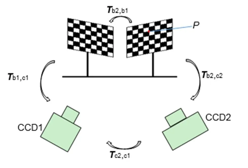
针对现有标定方法在相机无公共视场情况下的局限性,本文提出使用双平面标定板对双相机进行同时标定的方法。通过推导两个相机与两个标定板间的坐标变换,将待标定相机与参考相机的相对位姿关系的求解转换为较为成熟的手眼标定方程求解。通过实验验证:该方法可实现双相机的同时标定,且方法的绝对误差不超过0.089 mm,较为可靠;在双视角三维测量系统中,与相位-深度的累积误差不超过0.116 mm,可为进一步的数据融合提供可靠的初值。此外,由于本方法灵活方便,可适用于多视角三维测量系统的同时标定。
双视角测量;全局标定;系统标定;条纹投影
1 引 言
条纹投影测量法由于其结构简单、精度和分辨率高、可全场测量等突出的优点[1],被广泛应用在各个领域,其中单视角的条纹投影系统组成简单,能够快速、方便地测量被测目标物体的三维信息。目前关于单视角系统的研究已有很多[2-5],双视角系统是单视角系统的延伸,通过扩展相机的视场,获得更大范围的三维几何信息。在双视角三维测量系统中,两相机坐标系之间相互独立,所以需要确定两相机的相对位姿关系并将两相机坐标系统一到一个坐标系下,这一过程被称为全局标定,全局标定是实现双视角及多视角系统标定的关键[6]。
近些年来,国内外学者提出了许多双相机及多相机全局标定方法。例如,苏显渝等人[7]利用经纬仪或激光跟踪仪组成空间坐标系测量系统测得各个相机之间的角度及距离关系,求解出多相机之间的转换关系。鲁亚楠等人[8]提出了通过旋转台带动平面标靶旋转适当角度,即可求解出旋转台旋转角度与待标定相机坐标系之间的非线性关系,得到多相机之间的转换矩阵的方法。Liu Z等人[9]使用激光雷达扫描得到组成立体靶标的三个标板之间的位姿关系,然后利用该立体靶标完成三个相机的标定。以上方法简单有效,但是均需借助辅助设备,成本较高。Besl等人[10]基于ICP(iterative closest point)算法提出了多视角三维数据的融合方法,该方法及其改进算法后来也成为相机视角中应用最广泛的融合算法。但是,两相机相对位姿关系初值的准确性会直接决定ICP算法的速度和鲁棒性,对于多相机初值的确定有以下几个方法:楚圣辉等人[11]将一个大平面标定板置于4个待标定相机的公共视场内,以标定板为中介统一各个相机坐标系到一个坐标系来完成多相机的全局标定,但是该方法只适用于多相机视角方向一致的情况;潘华伟等人[12]对该类方法进行改进,采用平面标定板依次标定两个相邻相机的内外参数,最后逐个将各相机坐标系转换到一个相机坐标系,该方法虽然可完成无公共视场的多个相机的标定,但是操作复杂且无法实现多相机的同时标定。郎威等人[13]提出了通过旋转台带动平面标靶旋转适当角度,求解出旋转台旋转角度与待标定相机坐标系之间的转换关系,继而求得多相机之间的相对位姿关系,该方法性能稳定,但只能获取特定视角下三维数据的位置关系。
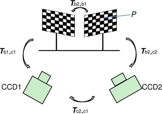
本文针对现有双视角及多视角三维测量系统中全局标定方法中存在的局限性,提出了一种利用两块平面标定板实现双视角全局标定的方法:将待标定相机坐标系与参考坐标系的转换矩阵的求解转换为机器人领域中研究较为成熟的手眼标定方程的求解问题。该方法无需额外的辅助设备,操作简单,且可满足大部分测量场景的精度要求。

图1 测量系统模型
2 标定原理
2.1 子系统标定原理
单视角相移条纹投影测量系统的数学模型如图1所示。经过一系列公式推导,相位和深度数据之间的关系可用一个多项式对其进行拟合[14]:

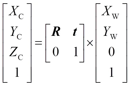
由于标定板中所有标识点的w和w是精确已知的,因此可以通过该标识点找到相机坐标系中所有特征点的位置。将标定板在相机和投影仪的公共市场内任意摆放若干个位置,并令中间的一个位置为参考面,则该参考面可描述为


一旦平面方程的参数确定,其他任何位置的标定板上的点对应参考面的高度便可表示为

这样标定板只要在相机和投影仪的公共视场内任意摆放若干个位置便可完成每个视角下相对深度值。相对相位值可通过相移法[15]及最佳条纹法相结合的方法获取。
2.2 双视角全局标定原理

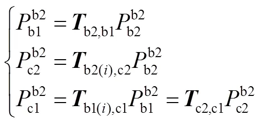

考虑双平面标靶的第次和次这两个摆放位置,结合两个标定板之间位置关系不变、两个相机之间位置关系也不变这两个约束条件,则可将式(6)整理得:
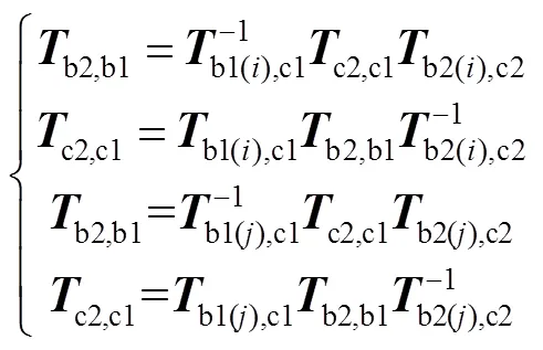
进一步的整理合并可得:

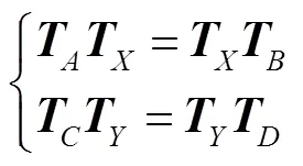


3 实验验证及结果
为了验证本文提出的标定方法的准确性,根据条纹投影三维测量技术的原理,研制了一套如图3所示的双视角三维测量系统固定于光学平台上,作为该课题所需的硬件系统。选用精度高、可靠性强且输出稳定的BenQCP270的数字投影仪一台,物理分辨率是1024 pixels×768 pixels;选用具有高速传输、信噪比高、实用性强等优点的SVS-eco655CVGE相机两台,其分辨率为1280 pixels×1024 pixels,搭配的镜头的变焦焦距为12 mm~36 mm。
首先完成两个视角的相机标定及全局标定,标定用的双棋盘格标定板如图4,其中每个标定板上的棋盘格数量为13×12,每个棋盘格的边长为6 mm,两个标定板之间的位置灵活可调,当两个相机均可拍摄到较高质量的图像时,对两个标定板分别进行固定,使两个标定板固定连接为一体。具体标定流程如下:
步骤1:将如图5所示的双平面标定板摆放于相机视场中20个位置,使每个位置与相机光轴有较大的夹角并尽量使其与光轴对称;
步骤2:相机1拍摄标定板1,相机2拍摄标定板2,两相机分别将采集到的标定板图像传输到计算机;
步骤3:分别载入两个相机采集的图像,输入特征点物理间距,提取特征点角点坐标,使用张正友法完成两相机的内参及畸变系数的标定;
步骤4:利用标定出的畸变系数对两个棋盘格标定板的图像坐标进行畸变校正,并重复步骤3,更精确求解出相机的内参。
步骤5:利用本文提出的多相机全局标定方法和已修正畸变的双平面标定板上的特征点的像素及相机坐标,进行全局标定。


为了验证全局标定精度,将一个较大的高精度陶瓷平面标定板摆放在两个相机前,如图5所示,该标定板棋盘格的标准间距为20 mm。假设相机1拍摄的特征点在相机1坐标系下的三维坐标为b1,其相邻特征点在相机2坐标系下的三维坐标为b2。根据全局标定结果将b2转换到相机1坐标系下得到b1。计算b1与b1之间的距离,将计算距离与真实距离之间的误差作为全局标定的绝对误差。本文将验证标定板摆放了三个位置,每个图验证位置处选择如图6中标红的44个距离,计算得到的最大误差、最小误差和平均误差如表1所示。
由全局标定的验证结果可知,本文确定的全局标定方法标定误差最高为0.089 mm,标定结果较为可靠。
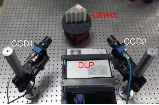
图3 双视角三维测量系统
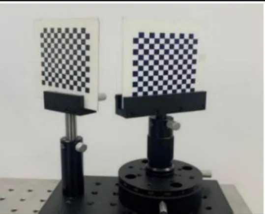
图4 双棋盘格标定板
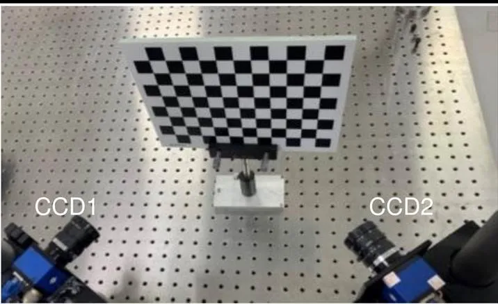
图5 全局标定精度验证
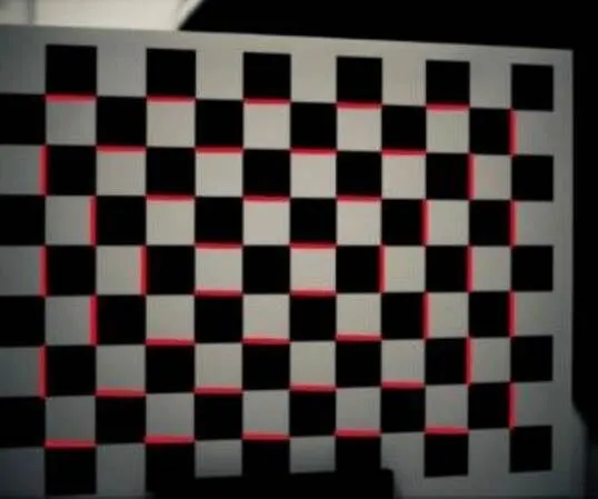
图6 选取的验证距离
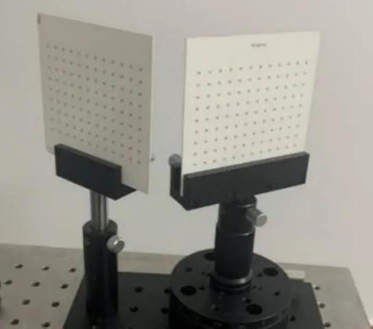
图7 双圆环标定板

表1 全局标定精度验证结果
由于条纹投影三维测量中需要向标定板投射高对比度的条纹以完成相位的提取,但由于标定板上黑色棋盘格部分对条纹具有低反射率,解算得到的绝对相位会缺失一部分的相位数据,导致最终标定精度的下降。故在两个子系统的同时标定中采用如图7的两个等间距圆环标定板完成,其中每个标定板上的圆环数量为9×12,每两个相邻圆环中心的间距为7.5 mm。这样每个视角都使用的是对应的圆环标定板进行标定,从而既可以实现无重叠视场节点间的同时标定,还可以避免圆环由于倾斜角度过大而导致的圆心偏差。本系统选择的相移条纹数为100、99及90,每组条纹图之间的相位差为π/2,即每组条纹图都符合四步相移法。
系统标定完成之后,使用具有平行面的台阶来验证系统精度,该台阶面之间的真实间距由精度为1 μm的三坐标测量仪测得。与系统标定实验相同,利用相移法及最佳条纹相结合的方法获得台阶表面的绝对相位信息,由已标定的系统参数和得到的台阶的展开相位可算出每个台阶面上所有点的相对深度,恢复出台阶的三维形貌。如图8为视角1恢复的实验结果,图9为视角2恢复的实验结果。在每个台阶面上选择靠台阶面中间的大部分点拟合出5个相互平行的平面,然后在每个台阶面上均匀地取一定量的点,利用Geomagic 11中的工具测量它们到相邻台阶面的距离,再对其进行平均,就可比较准确地得到相邻台阶面的测量间距。
由于两个视角恢复出的三维点云在两个相机坐标系中,而两个相机坐标系之间的转换关系已通过全局标定得到,于是我们将两片点云转换到一个坐标系下进行融合,融合结果如图10所示,可见无明显的分层和错位的现象。然后同样对融合的台阶面之间的距离进行拟合计算,便可得到融合台阶的测量结果。视角1、视角2恢复出的台阶以及两视角融合台阶的测量距离和测量误差见表2,由实验结果可知,本文采用的全局标定方法和子系统标定方法的累计误差不超过0.116 mm。
4 结 论
本文针对双视角三维测量系统同时标定方法进行了研究。针对现有标定方法中存在的局限性,采用一种新的方法,以双平面标定板为中介,求解出待标定相机坐标系与参考坐标系的转换矩阵。该方法无需辅助设备便可以实现无公共视场的双视角系统的同时标定,增强了标定的灵活性。此外,本文确定的全局标定方法适用于多视角三维测量系统,当相机数量多于两个时,增加对应相机数量的标定板,便可实现多个相机的同时标定。
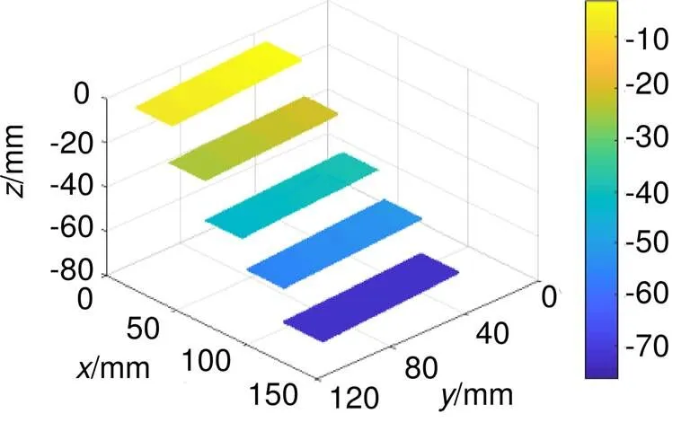
图8 视角1恢复的台阶三维形貌
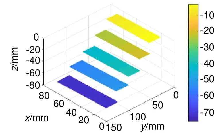
图9 相机2视角恢复的台阶三维形貌
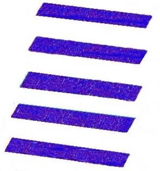
图10 两视角融合效果图

表2 双视角测量结果(单位:mm)
[1] Bai X F, Zhang Z H. 3D shape measurement based on colour fringe projection techniques[J]., 2017, 38(8): 1912–1925. 白雪飞, 张宗华. 基于彩色条纹投影术的三维形貌测量[J]. 仪器仪表学报, 2017, 38(8): 1912–1925.
[2] Tang Y, Chen W J, Zhang Q,. BP neural network applied to 3D object measurement based on fringe pattern projection[J]., 2007, 34(12): 61–65. 唐燕, 陈文静, 张强, 等. 神经网络获取三维面形研究[J]. 光电工程, 2007, 34(12): 61–65.
[3] Li B W, Zhang S. Superfast high-resolution absolute 3D recovery of a stabilized flapping flight process[J]., 2017, 25(22): 27270–27282.
[4] Fan S H, Liu C R, Qi X T,. Accuracy analysis and verification of structured light 3D measurement system[J]., 2014, 41(5): 52–56. 范生宏, 刘昌儒, 亓晓彤, 等. 结构光三维测量系统精度分析及验证[J]. 光电工程, 2014, 41(5): 52–56.
[5] Luo J, Yuan J H. Geometric calibration method of 3D photogrammetric instruments using grating projection[J]., 2005, 32(11): 43–48, 67. 罗剑, 袁家虎. 光栅投影式三维摄影测量仪的几何标定方法[J]. 光电工程, 2005, 32(11): 43–48, 67.
[6] Chen M Y, Tang Y C, Zhou X J,. High-accuracy multi-camera reconstruction enhanced by adaptive point cloud correction algorithm[J]., 2019, 122: 170–183.
[7] Su X Y, Cheng X X, Guo L R. An automated method for 360° surface measurement of 3-D objects[J]., 1989, 9(7): 670–672. 苏显渝, 程晓雪, 郭履容. 三维物体360°面形自动测量方法[J]. 光学学报, 1989, 9(7): 670–672.
[8] Lu Y N, Wan Z J, Wang X J. Solution to relative position of cameras without public FOV[J]., 2017, 38(3): 400–405. 鲁亚楠, 万子敬, 王向军. 一种无公共视场相机位置关系的求解方法[J]. 应用光学, 2017, 38(3): 400–405.
[9] Liu Z, Meng Z Z, Gao N,. Calibration of the relative orientation between multiple depth cameras based on a three-dimensional target[J]., 2019, 19(13): 3008.
[10] Besl P J, McKay N D. A method for registration of 3-D shapes[J]., 1992, 14(2): 239–256.
[11] Chu S H, Zhang H M, Chen S,. Research on the calibration method of multi eye stereo vision in large scenes[J]., 2017(15): 33–38. 楚圣辉, 张慧萌, 陈硕, 等. 大场景下多目立体视觉标定方法的研究[J]. 现代计算机(专业版), 2017(15): 33–38.
[12] Pan H W, Yang Z X, Gao C M,. Multi-camera calibration method using planar patterns[J]., 2011, 28(11): 4357–4360. 潘华伟, 杨振先, 高春鸣, 等. 一种基于平面模板的多摄像机标定方法[J]. 计算机应用研究, 2011, 28(11): 4357–4360.
[13] Lang W, Xue J P, Li C H,. Splicing of multi-view point clouds based on calibrated parameters of turntable[J]., 2019, 46(11): 1104003. 郎威, 薛俊鹏, 李承杭, 等. 基于旋转台参数标定实现多视角点云拼接[J]. 中国激光, 2019, 46(11): 1104003.
[14] Zhang Z, Zhang D, Peng X. Performance analysis of a 3D full-field sensor based on fringe projection[J]., 2004, 42(3): 341–353.
[15] Zhou C L, Si S C, Gao C Y,. Two-step phase-shifting profilometry based on Gram-Schmidt orthonormalization[J]., 2013, 40(6): 37–42. 周灿林, 司书春, 高成勇, 等. 基于格莱姆-施密特正交化两步相移轮廓术[J]. 光电工程, 2013, 40(6): 37–42.
[16] Tsai R Y, Lenz R K. A new technique for fully autonomous and efficient 3D robotics hand/eye calibration[J]., 1989, 5(3): 345–358.
[17] Mao J F, Shao H F, Jiang L,. Quaternion geometrical analysis on solving equationRR=RR[J]., 2010, 15(6): 951–957. 毛剑飞, 邵黄芳, 蒋莉, 等. 求解方程RR=RR的四元数几何研究[J]. 中国图象图形学报, 2010, 15(6): 951–957.
[18] Wang C Y, Li L J. Hand-eye calibration algorithm for robot based on quaternion[J]., 2019, 38(12): 133–135. 王昌云, 李立君. 基于四元数的机器人手眼标定算法[J]. 传感器与微系统, 2019, 38(12): 133–135.
[19] Hu W, Liu C, Fu L,. An algorithm for robot hand eye calibration with high accuracy[J]., 2018, 43(9): 19–24. 胡为, 刘冲, 傅莉, 等. 一种高精度的机器人手眼标定算法[J]. 火力与指挥控制, 2018, 43(9): 19–24.
[20] Wei Z Z, Gao M, Zhou F Q,. Robot extended eye-in-hand calibration method based on an assistant camera[J]., 2008, 35(9): 76–80, 121. 魏振忠, 高明, 周富强, 等. 基于辅助摄像机的机器人延伸手眼标定方法[J]. 光电工程, 2008, 35(9): 76–80, 121.
Method of simultaneous calibration of dual view 3D measurement system
Zhao Hanzhuo, Gao Nan*, Meng Zhaozong, Zhang Zonghua
College of Mechanical Engineering, Hebei University of Technology, Tianjin 300130, China
Global calibration diagram
Overview:The fringe projection measurement method is widely used in various fields due to its simple structure, high precision, and resolution, full field measurement, etc. The research on the single-view system of the fringe projection measurement method has been relatively mature. The dual-view fringe projection measurement system is an extension of the single-view fringe projection measurement system, a larger range of three-dimensional geometric information can be obtained by expanding the camera's field of view. In the dual-view fringe projection measurement system, the three-dimensional measurement results of the subsystem are always restored in the camera coordinate system, while the two camera coordinate systems are independent of each other in the dual-view fringe projection measurement system. Therefore, it is necessary to solve the transformation relationship between the two camera coordinate systems, the process of solving the transformation relationship between the two camera coordinate systems is called global calibration. Global calibration is the most important task in the calibration of dual and multi view systems. However, the existing global calibration methods require expensive auxiliary equipment when the two cameras have no common field of view, which adds a certain cost to the calibration, and when the viewing angle of the system is more than two, the method of relying on the auxiliary equipment is limited. Aiming at the limitations of the existing global calibration methods, this paper proposes a method to achieve dual-view global calibration by using two plane calibration boards: Firstly, through a series of derivation, the problem of solving the transformation matrix between the two camera coordinate systems is transformed into the problem of solving the hand-eye calibration equation which is more mature in the field of robot; Secondly, adjust the two calibration boards to the appropriate position according to the placement of the camera, and fix the two calibration boards; Thirdly, place the two calibration boards at several positions in the field of view of the two cameras at the same time to obtain several equations; Finally, the conversion matrix between the two cameras is obtained by using the quaternion method, least square method, and nonlinear optimization. The method identified in this paper does not require additional auxiliary equipment, and it is proved by quantitative experiments: this method can realize the calibration of dual cameras simultaneously and the absolute error of the method does not exceed 0.089 mm, which is relatively reliable; in the dual-view 3D measurement system, the cumulative error of global calibration and phase-depth does not exceed 0.116 mm, which can provide a reliable initial value for further data fusion. In addition, the global calibration method determined in this paper is suitable for multi-view 3D measurement systems. When the number of cameras is more than two, the calibration board corresponding to the number of cameras can be added to achieve simultaneous calibration of multiple cameras.
Zhao H Z, Gao N, Meng Z Z,Method of simultaneous calibration of dual view 3D measurement system[J]., 2021, 48(3): 200127; DOI:10.12086/oee.2021.200127
Method of simultaneous calibration of dual view 3D measurement system
Zhao Hanzhuo, Gao Nan*, Meng Zhaozong, Zhang Zonghua
College of Mechanical Engineering, Hebei University of Technology, Tianjin 300130, China
In view of the limitations of the existing methods when the camera has no common field of view, this paper proposes a method of using two plane calibration plates to calibrate two cameras at the same time. By deriving the coordinate transformation between the two cameras and two calibration plates, the solution of the relative pose relationship between any camera and the reference camera is transformed into a more mature hand-eye calibration equation. The experimental results show that this method can achieve simultaneous calibration of two cameras, and the absolute error is less than 0.089 mm. In the dual vision 3D measurement system, the cumulative error with phase height is less than 0.116 mm, which can provide a reliable initial value for the next step of data fusion.
dual vision measurement; global calibration; system calibration; fringe projection
Major Project of the Scientific Equipment Development of China (2017YFF0106404), National Natural Science Foundation of China (51675160), and Major Basic Research Projects of Hebei Applied Basic Research Program (15961701D)
10.12086/oee.2021.200127
TH741
A
* E-mail: ngao@hebut.edu.cn
赵涵卓,高楠,孟召宗,等. 双视角三维测量系统同时标定方法[J]. 光电工程,2021,48(3): 200127
Zhao H Z, Gao N, Meng Z Z,Method of simultaneous calibration of dual view 3D measurement system[J]., 2021, 48(3): 200127
2020-04-18;
2020-09-14
国家重大科学仪器设备开发重点专项(2017YFF0106404);国家自然科学基金资助项目(51675160);河北省应用基础研究计划重点基础研究资助项目(15961701D)
赵涵卓(1992-),女,硕士研究生,主要从事光学三维测量的研究。E-mail:972466185@qq.com
高楠(1982-),男,博士研究生,副教授,主要从事光学测量与光谱检测方面的研究。E-mail:ngao@hebut.edu.cn
版权所有©2021中国科学院光电技术研究所
