A novel launch dynamics measurement system for multiple launch rocket system and comparative analysis with numerical simulations
2021-03-23LilinGuXiotingRuiGuopingWngYiAnFufengYngMinWei
Li-lin Gu ,Xio-ting Rui ,*,Guo-ping Wng ,Yi An ,Fu-feng Yng ,Min Wei
a Institute of Launch Dynamics,Nanjing University of Science and Technology,Nanjing 210094,PR China
b School of Physical and Mathematical Science,Nanjing Tech University,Nanjing 211816,PR China
Keywords:Multiple launch rocket system Photoelectric sensor Launch dynamics measurement system Model verification Transfer matrix method for multibody systems
ABSTRACT In this paper,a novel launch dynamics measurement system based on the photoelectric sensor pair is built.The actual muzzle time(i.e.a time duration that originates from the initial movement to the rocket’s departure from the muzzle)and the muzzle velocity are measured.Compared with the classical methods,the actual muzzle time is obtained by eliminating the ignition delay.The comparative analysis method is proposed with numerical simulations established by the transfer matrix method for multibody systems.The experiment results indicate that the proposed measurement system can effectively measure the actual muzzle time and reduce the error of classical methods,which match well with the simulation results showing the launch dynamics model is reliable and helpful for further analysis and design of the MLRS.
1.Introduction
Multiple Launch Rocket System(MLRS)has been continuously developed and diffusely employed in recent years,which has attracted many researchers focusing on improving its performance[1-4].An accurate model helps analyze and design the MLRS to improve its performance.However,the dynamics modeling problem is very complicated.The MLRS itself is a complex rigid-flexible coupled multibody system and the motion of rockets in the tubes influence its response during the launching process.The launch dynamics of rockets should also be taken into consideration when studying the dynamics modeling issue of the MLRS.Many scholars have made efforts to improve the accuracy of the model.Cochran et al.[5,6]established a mechanical model of two rigid bodies including barrels and rockets and simulated the launch process of MLRS.Weeks et al.[7]studied the coupled-interaction between the flexible launch tube and the rocket,then proposed an effective numerical solution.Bi et al.[8]built the model of the MLRS based on the Kane-Huston method,considering the interaction between the tube and the rocket as numerical terms.Rui et al.[9,10]deduced the general launch dynamics equations of an asymmetric rocket and established the multi-rigid-flexible-body model of MLRS based on the transfer matrix method for multibody systems(MSTMM),which provided a more accurate way to simulate the launch dynamics of the MLRS.
However,the effectiveness of the model is eventually validated by experimental results[11-13].The validation should be focused on the muzzle time and muzzle velocity of the rocket,as well as the vibration of the MLRS.As shown in Fig.1,the rocket’s muzzle time is the instant when the rear bourrelet leaves the muzzle.The muzzle time plays a vital role in the analysis of the dynamics of the MLRS.The precise muzzle time helps obtain accurate initial disturbance,which has an essential effect on the impact dispersion of rockets[14-16].The muzzle velocity is the rocket’s velocity at the muzzle time and it is an important parameter for evaluating the rocket’s ballistic performance.The vibration of the elevation part(especially the angular velocities)significantly influence the initial disturbances of rockets.
Currently,the measurement devices[17-22]of the muzzle velocity mainly include radars,pressure sensors,high-speed cameras,and region truncation devices.Due to the rocket being a slender body,the above methods’results are the velocities of the rockets flying a distance away from the muzzle,not the actual muzzle velocity.The techniques for measuring the muzzle time[23-25]mainly include radar wave,high-speed camera photography,on-off target,and recoil displacement methods.The muzzle time measured in classical studies(called overall muzzle time in the paper)is a time duration form the rocket’s ignition to the departure from the muzzle.However,the actual time the rocket start moving is later than the ignition in the physical world,because there is a random ignition delay.Hence,the measured time by classical methods is not the actual muzzle time from the rocket’s initial movement to the departure from the muzzle(called actual muzzle time in the paper).This brings error for the internal ballistics analysis and makes it challenging to validate the numerical modeling.It also brings troubles for some advanced control methods of the MLRS using thrusters[26-28],because these control systems are active during the rocket’s launching process and the acquisition of the actual muzzle time has a considerable impact on the system design.

Fig.1.The schematic diagram of a rocket in the launch tube.
Therefore,in the sequel in this paper,a novel photoelectric sensor pair is first designed in Section 2 to obtain the actual muzzle time and the muzzle velocity of the rocket.Then,in section 3,a measurement system is built and a comparative analysis with numerical simulations based on the MSTMM is proposed.Finally,in Section 4,engineering applications are successfully carried out using the measurement system.Compared with the numerical simulation results,the proposed system can successfully measure the actual muzzle time and the MLRS’s launch dynamics model is validated.The conclusion is drawn in Section 5.
2.The photoelectric sensor pair
The rocket’s launching process in the tube is very complex and involved with combustion,collision,and friction.The muzzle time is very short,often only approximately 100 ms.So,the measurement for muzzle time and muzzle velocity is required to be antiinterference to the fire and smoke,respond rapidly,and with high precision.The photoelectric sensor measures the object’s movement by diode using a binary mechanism receiving the laser or not.Since the diode’s rising time and falling time are less than 100 ns,the photoelectric sensor can respond rapidly to the measured motion with high precision,which is suitable for measuring the launch dynamics of the MLRS.The photoelectric sensor pair is designed to measure the actual muzzle time and muzzle velocity.
2.1.The photoelectric sensor
The structure of the photoelectric sensor is depicted in Fig.2,which consists of a support setting,a laser emitting diode(SFH4547)and a laser receiving diode(OPL810).
Fig.2.The structure of the photoelectric sensor.
Fig.3 shows the measuring principle of the photoelectric sensor and Fig.4 shows the corresponding output signal.The photoelectric sensor is mounted perpendicular to the moving direction of the measured object.The emitting diode continuously emits the 940 nm laser under the charge.The receiving diode produces a high-level signal UHwhen receiving the laser from the emitting diode.The measured object approaches the photoelectric sensor in the moving direction.When the measured object reaches the photoelectric sensor at the configuration plotted in solid line in Fig.3,the laser generated by the emitting diode will be blocked by the measured object.At the same time,the receiving diode will produce a low-level signal ULat td,indicating the time that measured object reaches the photoelectric sensor,as shown in Fig.4.When the measured object leaves the photoelectric sensor at the configuration plotted dashed line in Fig.3,the output signal of receiving diode returns to the high-level signal UHat tu,indicating the time that the measured object leaves the photoelectric sensor,as shown in Fig.4.In summary,the object reaches the photoelectric sensor at tdand leaves at tu.The velocity that the measured object passes through the photoelectric sensor is defined as

Fig.3.The measuring principle of the photoelectric sensor.
Fig.4.The output signal of the photoelectric sensor.
where l is the width of the receiving area and L is the length of the measured object in the moving direction perpendicular to the photoelectric sensor.
2.2.The photoelectric sensor pair
Because the rocket is a slender body,its motion is difficult to measure directly.As shown in Fig.1,the guide button is fixed on the rocket’s rear bourrelet.Hence,the photoelectric sensor pair is designed to measure the actual muzzle time and muzzle velocity by measuring the guide button’s motion.
As shown in Fig.5(a),a pair of photoelectric sensors are installed at the tail and muzzle of one single launch tube,respectively.The tail photoelectric sensor is mounted on the through hole of the guide groove in Fig.5(b),which also coincides with the front of the rocket’s guide button when the rocket remains static before ignition.The muzzle photoelectric sensor is mounted on the muzzle of the guide trough and aligned with the front section surface of the launch tube in Fig.5(c).
Fig.5.The schematic diagram of the photoelectric sensor pair:a)The location;b)The tail photoelectric sensor;c)The muzzle photoelectric sensor.
Fig.6 shows the output signal of the photoelectric sensor pair.The output signal is at the high level UHat first.The tail photoelectric sensor is installed at the front of the rocket’s guide button when it is still.Once the rocket starts to move,the guide button blocks the laser emitted by the emitting diode of the tail photoelectric sensor,and the receiving diode generates a low-level signal ULat time t1.When the guide button leaves the tail photoelectric sensor,the output signal of the receiving diode returns to high level UHand the time is recorded as t2.When the rocket leaves the muzzle,the guide button blocks the laser emitted from the emitting diode of the muzzle photoelectric sensor leading to a low-level signal ULgenerated by the receiving diode at time instant t3.When the guide button leaves the muzzle photoelectric sensor,the receiving diode recovers the high-level signal UHand the time is recorded as t4.

Fig.6.The output signal of the photoelectric sensor pair.
In summary,the rocket starts to move at t1and leaves the muzzle at t4.The actual muzzle time is

The measured object in Fig.3 is now substituted by the guide button of a rocket shown in Fig.7.This yields the muzzle velocity yields to
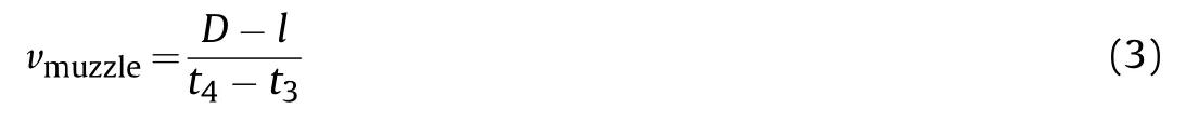
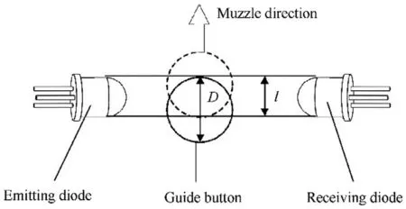
Fig.7.The measuring principle of muzzle velocity.
where l is the width of the receiving area and D is the diameter of the rocket’s guide button.
Cinderella went immediately to gather the finest she could get, and brought it to her godmother, not being able to imagine how this pumpkin could make her go to the ball. Her godmother scooped24 out all the inside of it, having left nothing but the rind; which done, she struck it with her wand,30 and the pumpkin was instantly turned into a fine coach,31 gilded25 all over with gold.32
3.The launch dynamics measurement system and comparative analysis with numerical simulation
Based on the proposed photoelectric sensor pair,a launch dynamics measurement system is set up in this section.Further,a comparative analysis method with simulation is proposed.
3.1.The launch dynamics measurement system
As shown in Fig.8,the launch dynamics measurement system is composed of an ignition controller,sensors,the photoelectric sensor pairs for each tube,and a data acquisition system.The rockets are fired within a determined time interval and sequence by the ignition controller.The sensors mounted on proper positions of the MLRS measure the concerned dynamics response.The signal sampled from the ignition controller,the photoelectric sensor pairs,and the dynamics response signal of the MLRS from sensors are received and saved by the data acquisition system.

Fig.8.The composition of the measurement system.
3.2.The comparative analysis method
Fig.9 shows the working flow of comparative analysis between experimental results and numerical simulations.Based on the time signal measured by the photoelectric sensor pairs and the ignition controller,the actual firing time of each rocket is calculated in the firing time processing.And the firing time is input to the numerical system.Finally,the experiment results,including the actual muzzle time,the muzzle velocity,and the dynamics response,are compared and analyzed with the simulation results.

Fig.9.The working flow of comparative analysis based on the measurement system.
3.3.Launch dynamics simulation of a MLRS
The general idea of the MSTMM[9,10,29-33]is to broken up a complex multibody system into elements,including bodies and hinges.The dynamics properties of these elements are summarized in a matrix form yielding the element transfer matrix,that are considered as building blocks for the assembly of the overall transfer equation of the system.The MSTMM has the advantages of a low order of matrix involved independently from the system degrees of freedom,flexible modeling,stylized programming,and high precision.
As shown in Fig.10,a MLRS can be divided into several components,including the wheels,the rear mechanical jacks,the vehicle chassis,the azimuth part,the elevation part,and the launch tubes.Therein,the rear mechanical jacks,the wheels,the vehicle,the azimuth,and the elevation part are modeled as rigid bodies with spatial motion.Launch tubes are divided into three segments,where one segment is considered as a rigid body undergoing spatial motion and while other two segments are uniformly considered as an elastic beam transversely vibrating in space.The elastic and damping effects between body elements are modeled as linear and rotary springs in parallel with dampers,respectively.
The launch dynamics modeling and simulation of a MLRS have been accomplished and published in Refs.[9,10],and[26].Fig.11 shows the flowchart of the numerical simulation.The dynamics model and topology of the MLRS are firstly established in Fig.12 according to Refs.[9,10,26,32].Mechanical elements are uniformly numbered.The state vector Zi,jis determined where the subscript denotes elements number and 0 boundary.Each element’s transfer matrix and transfer equation can be obtained with the library of transfer matrices.Based on the automatic deduction theorem,the overall transfer matrix of MLRS can be deduced.Applying the boundary conditions,the eigenequations and thus eigenvalues of the system can be obtained.Once the eigenvalues of the system and the boundary state vectors are computed,the internal state vectors of the system can be then obtained by successive use of element transfer matrices,thus eigenvectors of the MLRS can be extracted.With orthogonality conditions of augmented eigenvectors,the body dynamics equations of the MLRS in physical domain are then transformed into modal space,leading to the ordinary differential equations regarding the modal coordinates qk(t)which describe the dynamic response of the MLRS.Together with the equation of motion of the in-bore rocket,the launch dynamics of the entire system comprising the MLRS and the in-bore rockets can be established.Finally,the dynamics response can be calculated in combination with a numerical integration method e.g.the Runge-Kutta method.
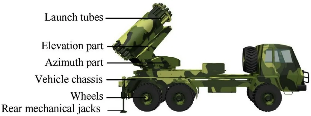
Fig.10.The mechanical structure of a MLRS.
With the established launch dynamics simulation system,the MLRS’s dynamics response,the rocket’s actual muzzle time,and muzzle velocity can be computed,which can be further validated by experimental results obtained with the proposed measurement system.
4.Experiment results and discussions
Engineering applications of the proposed launch dynamics measurement system are carried out on a certain type of MLRS with 18 tubes.Several groups of experiments have been carried out and 3 salvos of 18 rockets are showed as representative results.
4.1.The experiment setup
The experimental setup is shown in Fig.13.The firing interval between any two successive rockets is set as 1 s by the ignition controller(SOM-TL6748).The IMU(SDI-GC7050C,1000 Hz)is mounted on the elevation part platform,measuring the elevation part’s angular motions.Velocity sensors(MEAS 8011-06-500)are mounted on the elevation part and the right side of the azimuth part,respectively,measuring the elevation and azimuth parts’velocities.Due to the rise time and fall time of the diodes being less than 100 ns,the data acquisition system’s sampling rate is set as 100 M/s for every photoelectric sensor.
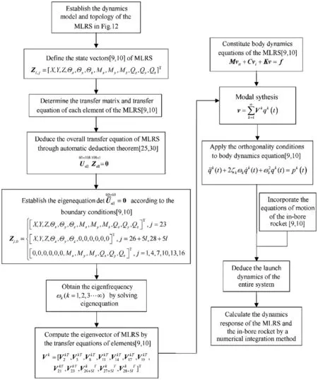
Fig.11.The flowchart of the launch dynamics simulation of a MLRS.
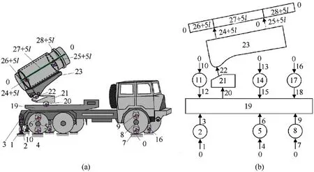
Fig.12.The model of the MLRS:a)The dynamics model;b)The topology.

Fig.13.The experimental setup.
4.2.Experiment results of the photoelectric sensor pairs
Fig.14 exhibits the testing results of the photoelectric sensor pair corresponding to one shot of the rocket to show the data processing.The falling edge of the tail photoelectric sensor signal corresponds to the rocket’s actual firing time,so the time interval between the falling edge of the ignition signal and that of the tail photoelectric sensor signal is the rocket’s ignition delay.The time interval between the falling edge of the ignition signal and the rising edge of the muzzle photoelectric sensor signal is the overall muzzle time obtained by classical testing methods.The time interval between the falling edge of the tail photoelectric sensor signal and the rising edge of the muzzle photoelectric sensor signal is the actual muzzle time of the rocket.Then,the muzzle velocity can be obtained using Eq.(3)in combination with the time interval between the falling and rising edge of the muzzle photoelectric sensor signal.
The testing results obtained by the photoelectric sensor pair corresponding to each rocket are processed under the above process.Fig.15 and Fig.16 show the experiment results of muzzle velocity and muzzle time of the 3 salvos of 18 rockets.From Fig.15,the muzzle velocity varies from 37.15 m/s to 45.96 m/s and the average velocity is 42.10 m/s.It can be seen in Fig.16 that the actual muzzle time is from 112.17 ms to 120.98 ms and the average value is 116.48 ms.However,the overall muzzle time is from 156.77 ms to 208 ms whose variation range is much larger.Fig.17 shows the ignition delay for each rocket.The rocket’s ignition delay varies stochastically in a relatively broad range,from 41.05 ms to 89.93 ms.The ignition delay shows no specific relationship with the firing order or loading position.It can be concluded that the rocket’s ignition delay is a random quantity,which cannot be predicted and must be measured in the experiments.Fig.18 gives the ratio of the ignition delay in the overall muzzle time,it varies from 25.71% to 43.47% with the average value of 34.14%.The ignition delay is the reason for the considerable variation of the overall muzzle time,which leads to inaccurate results.The proposed photoelectric sensor pair eliminates the random ignition delays in the overall muzzle time and dramatically reduces the test errors.Thus the proposed measurement system helps obtain precise initial disturbance to analyze the performance of the MLRS and benefits the vibration control during the launching process.
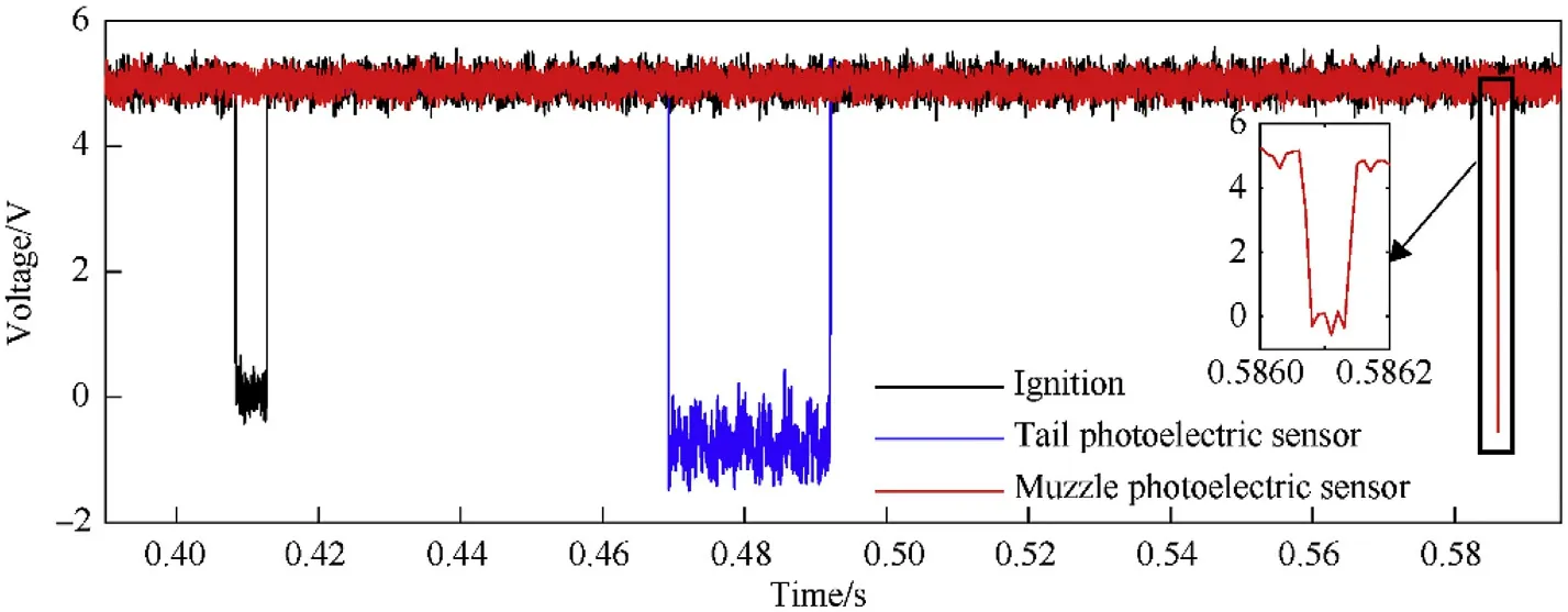
Fig.14.Experiment results of photoelectric sensor pair of a single shot.
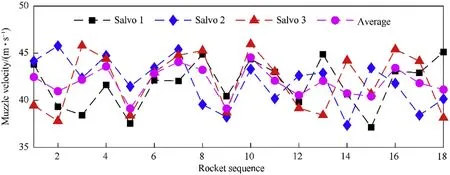
Fig.15.Experiment results of the rocket’s muzzle velocity of the 3 salvos of 18 rockets.

Fig.16.Experiment results of the rocket’s muzzle time of the 3 salvos of 18 rockets.
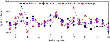
Fig.17.Experiment results of the rocket’s ignition delay of the 3 salvos of 18 rockets.
Fig.18.Ratio of the rocket’s ignition delay in overall muzzle time of the 3 salvos of 18 rockets.
4.3.Comparative analysis of dynamics response
The second salvo of 18 rockets is chosen as an example to carry out the dynamics response comparative analysis.Based on the tested ignition delay of each rocket,the firing interval for the numerical system is calculated as 1 s plus the ignition delay of each rocket,which is listed in Table 1.Simulation of launch dynamics of a salvo of rockets with the actual firing time of MLRS is carried outand the dynamics response is computed.The simulation time in the physical world is set as 19 s.
Table 1The actual firing time of MLRS.
Fig.19.The comparison results between experiment and simulation of the elevation part’s angular velocity in the x-direction.
Fig.20.The comparison results between experiment and simulation of the elevation part’s angular velocity in the y-direction.
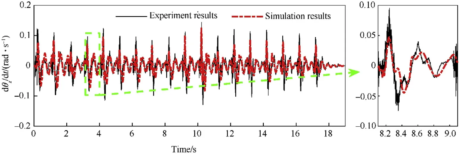
Fig.21.The comparison results between experiment and simulation of the elevation part’s angular velocity in the z-direction.
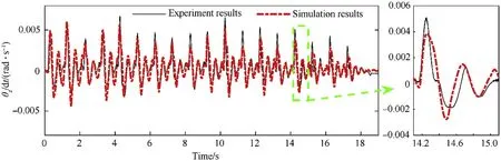
Fig.22.The comparison results between experiment and simulation of the elevation part’s angular displacement in the z-direction.
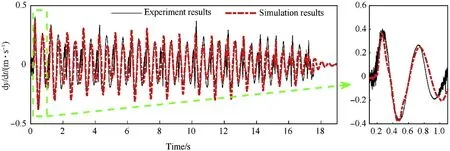
Fig.23.The comparison results between experiment and simulation of the elevation part’s velocity in the y-direction.
Fig.19 thru Fig.21 show the comparative results of the elevation part’s angular velocities.Fig.22 shows the comparative results of the elevation part’s angular displacement in the z-direction.Fig.23 shows the comparative results of the elevation part’s velocity in ydirection and Fig.24 shows the comparative results of the azimuth part’s velocity in the x-direction.It can be concluded from the figures that the tested dynamics response of the MLRS agrees well with the simulation results.However,in Fig.20,the maximum angular velocity results of the elevation part in the y-direction show differences in the phase between experiment and simulation.That is because the large gear size of the slewing mechanism results in the large random gear clearance and backlash in the physical system.These factors have not been considered in the numerical simulation,causing that the elevation part’s angular velocity in the y-direction do not match well.The average muzzle time and velocity obtained by the simulation are 117.5 ms and 41.43 m/s,respectively.The error is 0.87% and-1.59% compared with the average experiment value of 116.48 ms and 42.10 m/s,respectively.
5.Conclusion
In this paper,a novel launch dynamics measurement system based on the photoelectric sensor pair is designed,built,and manufactured.The actual muzzle time is first measured.The comparative analysis between experimental results and numerical simulations based on the MSTMM is proposed,which validates the launch dynamics model of a MLRS.The main conclusions are as follows:
1.The ignition delay is a random quantity and varies in a broad range,which has a significant impact on the overall muzzle time.The ratio of the ignition delay in the overall muzzle time ranges from 25.71% to 43.47%.It can be eliminated using the measurement system proposed in this paper.
2.The launch dynamic simulation system of MLRS is validated by the experiment results.It is useful for the analysis and design of the MLRS.
3.The proposed measurement system is easy to implement.Only with minor techniques for installation of the photoelectric sensor pairs on the launcher structure,the measurement system proposed can be employed for launch dynamic measurement of various weapon systems with launchers,not limited to the MLRS.
4.The proposed measurement system can also be employed as a sensor for the vibration control system of MLRS which is active during the launching process.The time instant corresponding to the initial movement of a rocket is vital in engineering applications and the muzzle time has a significant effect on the control design.
Funding sources
This work was supported by the National Natural Science Foundation of China Government(No.11972193).
Declaration of competing interest
The authors declare that they have no known competing financial interests or personal relationships that could have appeared to influence the work reported in this paper.
Acknowledgments
We owe special thanks to Dr.Jianshu Zhang,and Dr.Qinbo Zhou for their constructive suggestions to improve this paper.
杂志排行

Defence Technology的其它文章
- Ricochet quantification using a multiple sensor approach☆
- Reaction degree of composition B explosive with multi-layered compound structure protection subjected to detonation loading
- Effects of nano-sized aluminum on detonation characteristics and metal acceleration for RDX-based aluminized explosive
- Increasing of photostability of HNS explosive in the presence of UV photostabilizers
- Numerical investigation on cooling performance of filter in a pyrotechnic gas generator
- Decision support model for effects estimation and proportionality assessment for targeting in cyber operations