Quasi-steady aerodynamic characteristics of Terminal Sensitive Bullets with short cylindrical portion
2021-03-23YonglingYngRuiGuoRongzhongLiuLingChenBoyngXingBoZho
Yong-ling Yng ,Rui Guo ,*,Rong-zhong Liu ,Ling Chen ,Bo-yng Xing ,Bo-o Zho
a School of Mechanical Engineering,Nanjing University of Science and Technology,Xiaolingwei 200,210094,Nanjing,China
b The Seventh Design Department,Aerospace Science and Technology Corporation,The Seventh Research Institute,610100,Chengdu,China
c Unit 31102 of PLA,210000,Nanjing,China
Keywords:Turbulent flows around bluff body Critical regime Flow-induced structural vibration
ABSTRACT
1.Introduction
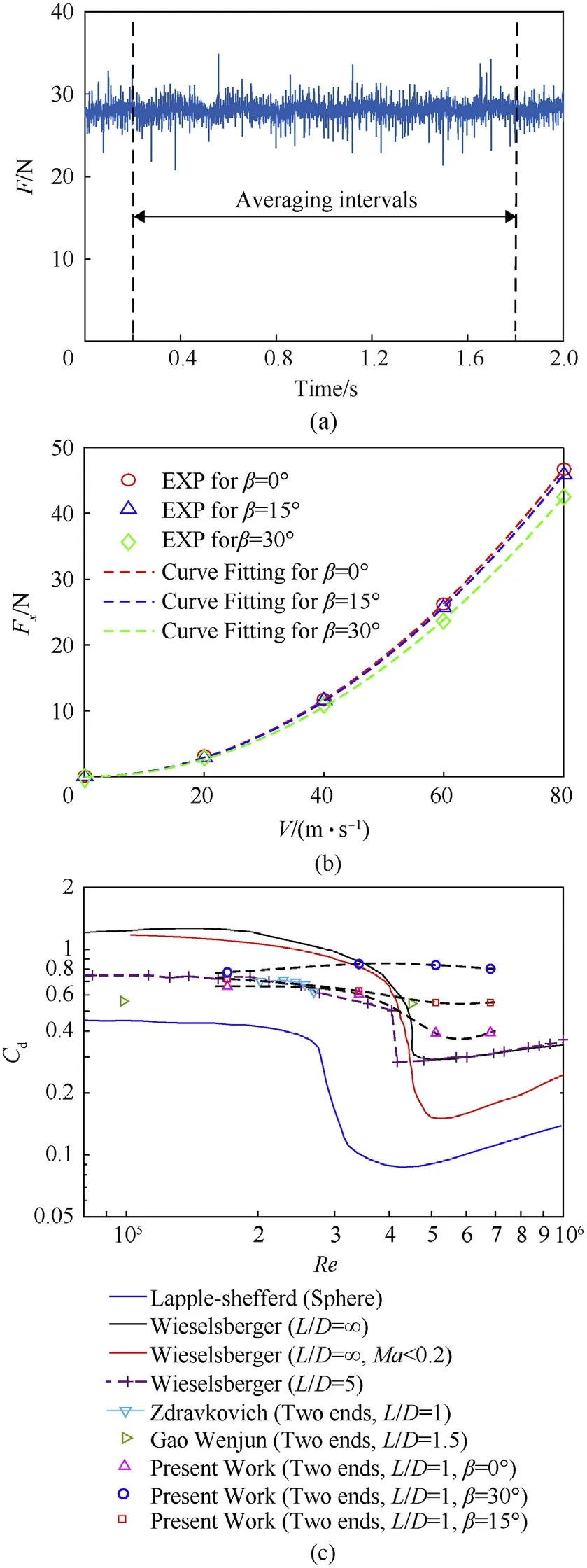
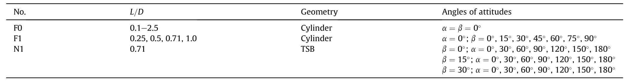
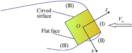
The short cylindrical Terminal Sensitive Bullets(TSB)consists a short cylindrical warhead and a millimeter wave detector(whose geometry is a cuboid).And the working processes[1](P1,P2,P3 and P4)of TSB and the definitions of coordinate system are shown in Fig.1.Where,C is the geometric center of the cylindrical warhead.For the wind axis coordinate system CXNYNZN(N),the CZNaxis is vertically upward,the CXNaxis is parallel to the freestream velocity and the direction is opposite,and the CYNaxis is determined by the right-hand rule to be perpendicular to the freestream velocity.The body axis coordinate system Cξ2ηZ1(B)can be obtained by rotating CXNYNZNtwice.For the first time,the CXNYNZNis positively rotated byαaround the CZNaxis to the position Cξ1ηZN.The second time is that the Cξ1ηZNis positively rotated byβaround the Cηaxis to reach the position Cξ2ηZ1.Among them,αis the roll angle andβis the pitching angle.In the field of TSB,an important angle between the cylinder axis and the plumb line is called scanning angle,which is determined by the pitch and yaw motion.And there is no yaw motion in present research,so angleβis also called the scanning angle in the following statements.These two angles determine the spatial attitude of the TSB during steady-state scanning motion[1].The details of the bullet’s geometric parameters are shown in the submap at the bottom right corner of Fig.1.
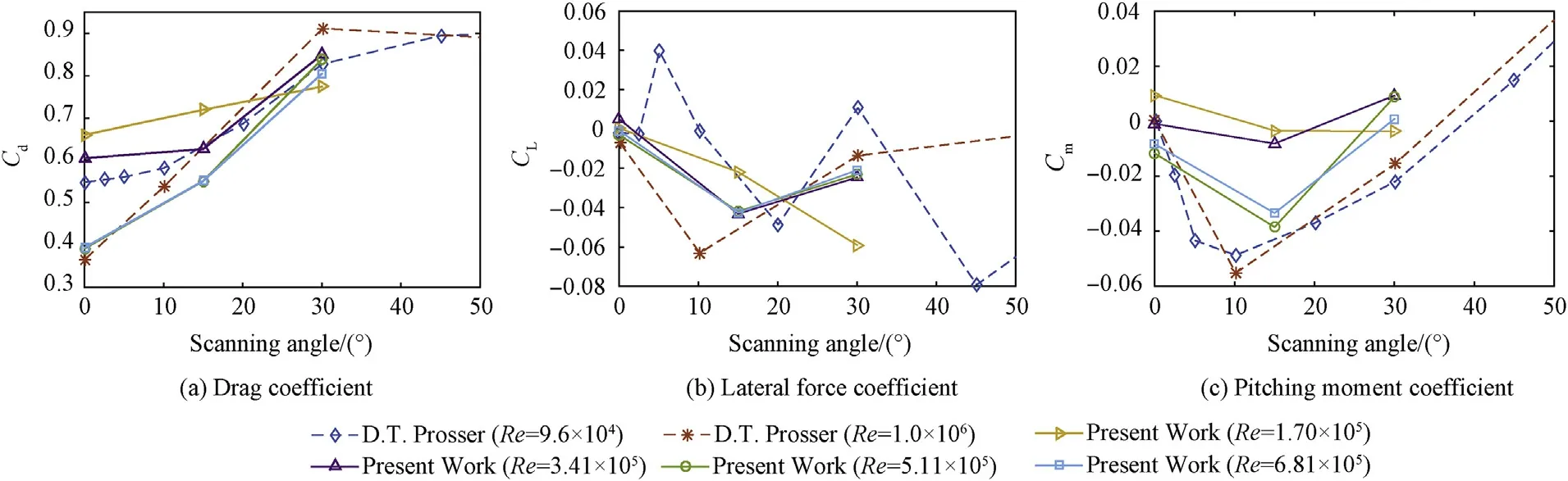
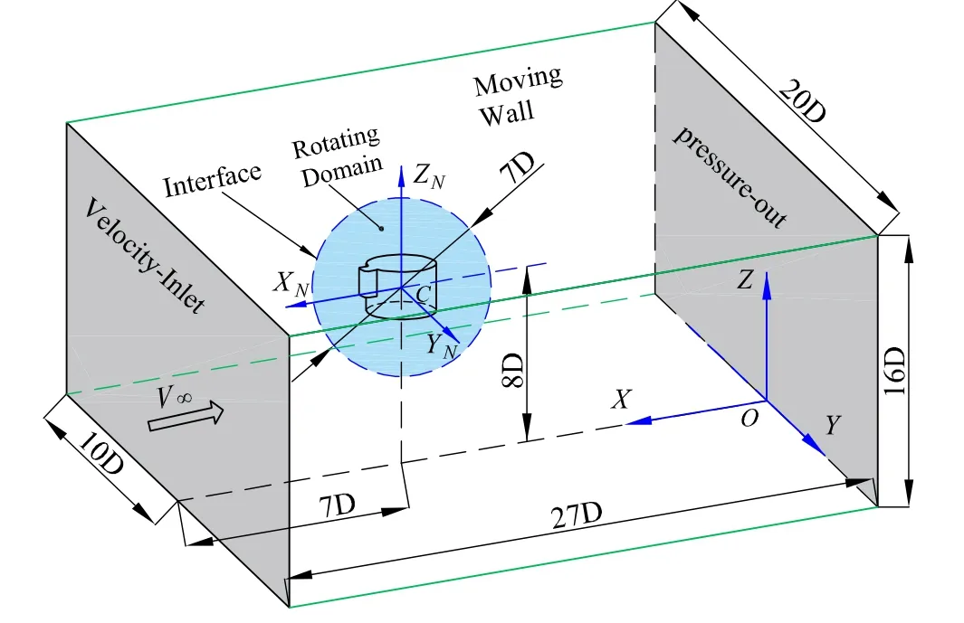
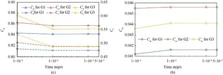
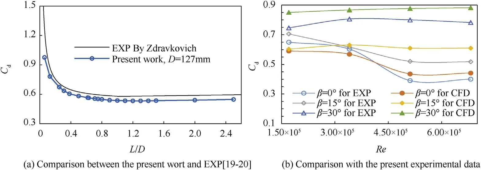
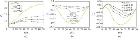
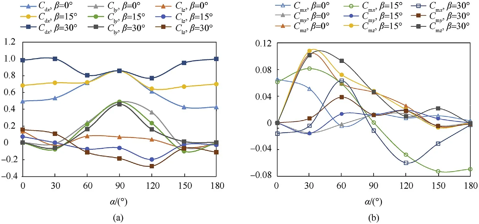
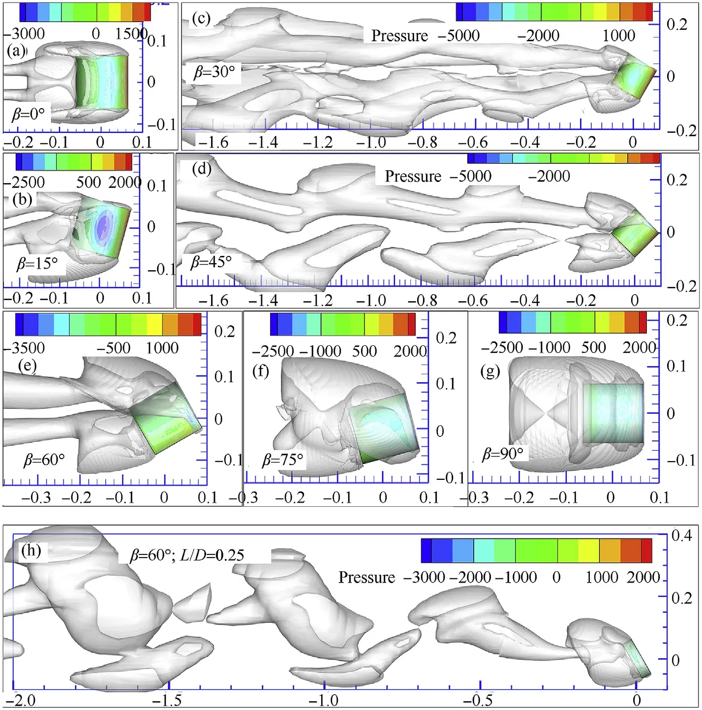
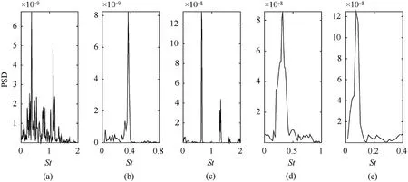
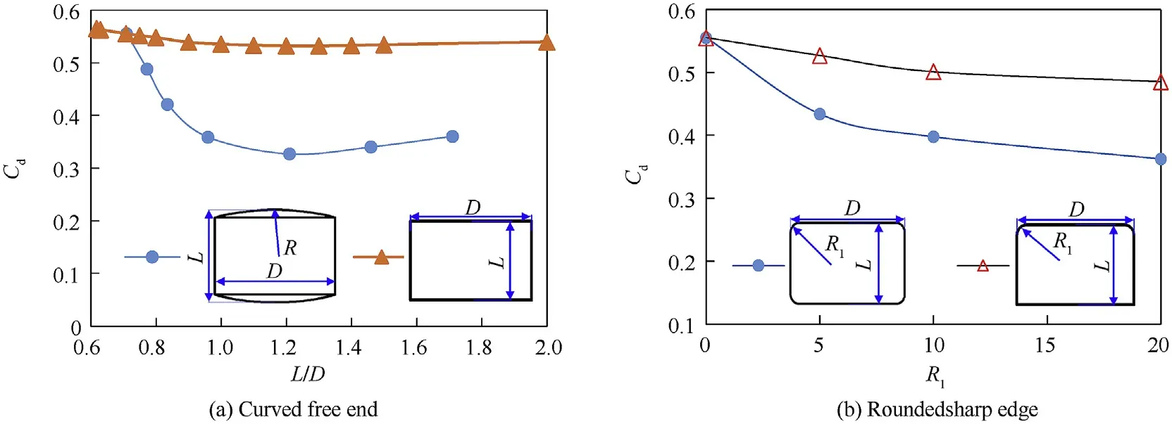
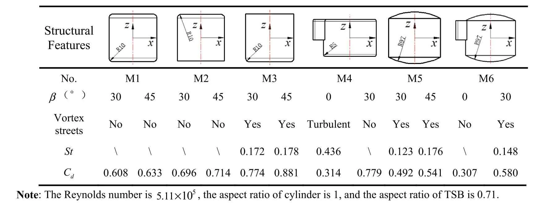
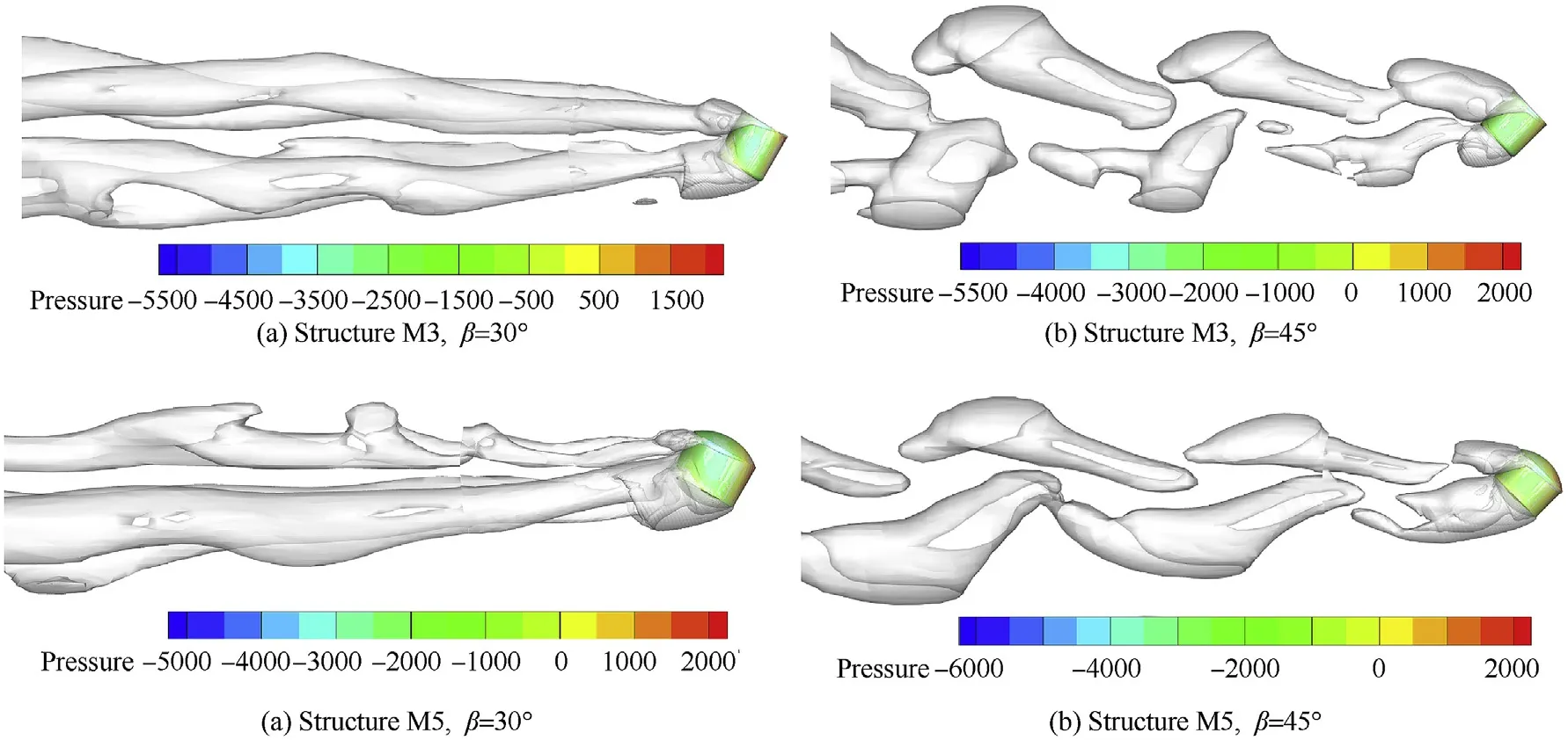
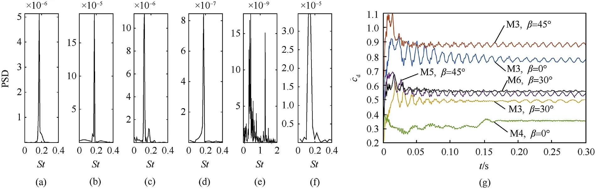
When switching from process P2 to P3,the TSB is thrown by the carrier at a horizontal velocity VC0,at this time,the aerodynamic characteristics of the TSB are similar to the flow around a short cylinder with two free ends.According to the classical boundary layer theory[2],when Reynolds number is 47 Fig.1.The working process of TSB and the definition of the coordinate system and the angles of attitude. At present,most of research works focus on the flow around infinite cylinder[3-8].However,the majority of practical applications are finite cylinder with one free end(chimneys,cylindrical tall buildings,etc.)or the cylinder with two free ends(submarines,torpedoes,wheels[9],the short cylindrical TSB in present works,etc.).As for the finite cylinder with one free end,the aspect ratio(L/D)of the cylinder becomes an important factor affecting the flow.At the aspect ratio of 2 There are relatively fewer studies on the flow around the finite cylinder with two free ends.Through the oil shadow experiment,Zdravkovich(1989)[19]found that the periodical vortex can be observed at the aspect ratio of 2 Till now,for the short cylindrical bluff body,there is a lack of detailed analysis about the influence of aerodynamic shape,Reynolds number and flight attitudes on aerodynamic characteristics and shear layer behavior,especially in the critical regime.However,there are a wide range of engineering requirements for this blunt body structure,such as discus,disc-shaped radar on AEW(Air Early Warning),low speed UAV(Unmanned Aerial Vehicle),samarashaped projectile and so on.Wind tunnel experiment is one of the most commonly used methods in the study of bullet aerodynamics,which has the advantages of high efficiency and accuracy.To obtain the relationships between Re,L/D and Cdin a larger range,the cylinders with two different diameter were used by Zdravkovich(1989)[19]in experiment,which is due to the limitation of maximum wind speed in the wind tunnel test section.Surprisingly,compared with the cylinder with D=68mm,the drag coefficient of cylinders with D=127mm decreases in the step-like way under the same Reynolds number and aspect ratio.Therefore,in order to accurately obtain the aerodynamic parameters,the wind tunnel experiments are carried out under the critical regime 1.7×10⁵ The aerodynamic force test of TSB is carried out in large-scale low-speed wind tunnel NH-2[33]in NUAA.The NH-2 is a closedend single-reflux low-speed wind tunnel with two test sections in series.The experiment is carried out in the small test section of NH-2 wind tunnel.The installation diagram of the model in test section is shown in Fig.2,and note that the diagram is not to scale.The two sides of the test section are equipped with optical glass observation windows,which can be used for model attitude observation and schlieren photography.In this test section,the corrected equivalent diffusion of the boundary layer is 0.25°,the cross section is rectangle 3m×2.5m,and the test length is 6 m.The maximum windward area of short cylinder is D2=1272mm2and the corresponding blockage rate is 0.22%.That is,this test section meets the requirement of flow field size with blockage rate less than 3%.Using the adjusting mechanism,the short cylinder can be connected with the balance,and the scanning angle can be changed in range of 0~30°. Fig.2.Sketch of wind tunnel experiment method.1).Cylindrical portion.2).Millimeter wave detector.3).Supporting rod.4).Adjusting mechanism for angleβ.5).The wall of the wind tunnel.6).Balance. A six-component mechanical strain balance is adopted in the experiment.The rated load of the balance is 4 times the estimated maximum aerodynamic force,which guarantees a high degree of safety in the experiment.The corresponding measurement precision is 0.12%.The sampling frequency of the balance is 100 KHz.The mechanical balance is calibrated before test.The rotation axis Oy of the adjusting mechanism is taken as the reference axis.The center of the cylinder is the reference point for the three moments.The aerodynamic parameters based on the geometric center of the cylinder are obtained by coordinate transformation.And according to the calibration results of each channel of the amplifier,a test system is available.In order to reduce the time taken for the installation and replacement of the experimental model,the modular design is adopted for the wind tunnel experimental model.That is,some feature components of the experimental model are designed to be removable and assembled.Combining the adjusting mechanism,different experimental conditions can be realized by replacing the feature components and adjusting freestream velocity V∞.Experimental model is mounted in wind tunnel test section as shown in Fig.3. At present,no one has conducted a wind tunnel experiment about the aerodynamic parameters of short cylinder with L/D≤1 under different scanning angles.Therefore,this paper firstly takes a short cylinder as the research object,and evaluates whether there is a drag crisis phenomenon[2](For the flow around an infinite cylinder and sphere,in the interval of 1×105 During each test,the balance continuously collects aerodynamic forces and moments for 2 s.The original experimental data are shown in Fig.4(a).When normalized,the data points within 0.2s-1.8s are selected for averaging to obtain the average aerodynamic coefficients.Support interference correction tests are carried out for all experiment cases.As shown by the dotted line in Fig.4(b),when theβis fixed,the drag and the incoming flow velocity have a quadratic function relationship.The results obtained by the fitting are F=aV2,where aβ=0°=0.7299,aβ=15°=0.7159,aβ=30°=0.6628,and the coefficients of determination are all higher than 0.999.And the same is true for the test results for lift and pitch moments.Then,the smoothing spline method is used to fit the experimental data as shown in Fig.4(c).For angleβ=0°and β=15°in the critical regime,the relationship between Cdand Re is similar to those observed by the infinite cylinder[2],the sphere[2]and the short cylinder[19].And in the interval of 2×10⁵ Fig.3.Experimental model mounted in wind tunnel test section:(a)front view,(b)side view,(c)text for correcting support interference. Table 1Wind tunnel experiment scheme(Cylinder,L/D=1) The relationship betweenβand time-averaged aerodynamic forces and moments is illustrated in Fig.5 under different Reynolds numbers.βhas a very large influence on Cdat 0°<β<30°.And Cdincreases linearly with the increase ofβat the Re=1.7×10⁵.These characteristics are similar to the simulation results of Prosser[22](L/D=1).However,when theβis large enough,the sensitivity of the Cdto the Re decreases.Whenβ>30°,there is little difference in Cdat different Reynolds numbers.This behavior shows that in the process from medium to highβ,the separation from the sharp edge becomes the main factor determining the total drag,and this behavior is relatively independent of the Reynolds number.However,it should be noted that since the reference area LD is used for normalization,at higher scanning angles,the difference in drag is practically not as large as the drag coefficient.Except at very low scanning angles,the Reynolds number has little effect on lateral force,whose direction is normal to the cylindrical axis,and pitching moment.Lateral force is insensitive to small flow changes,which also results in the smaller scales of change caused by Re than by the β.There is a turning point of pitching moment atβ=15°.This transition is related to a change in the shear layer behavior on both sides of the cylinder.However,the change of the pitching moment caused by the Re to becomes smaller as theβincreases. Structured and embedded grid is used to simulate the flow around short cylindrical TSB at different attitudes.Without any surface defects or wind tunnel supporting devices,the size of computational domain and boundary conditions are shown in Fig.6.The entire computational domain is divided into inner rotating domain and far-field static zones.By giving the specific rotational angles to the inner rotating domain,the attitudes of TSB at different scanning angles and roll angles can be realized.The center of rotation is located at the geometric center of the cylindrical portion,whose coordinate value is(0,0,0).The boundary interface is used to connect these two zones,and an interpolation method is used to transfer the flow field information at the interface.The upstream entrance of the far-field static zone adopts the velocity-inlet boundary,the downstream exit adopts the pressureoutlet.Usually,the extension distance of the computational domain from the origin to the upstream and the span is 5-20D[7,13,26,31,32].The extension distance 6D,7D,8D,and 10D are used to analyze the effect of wall boundary on the flow.After the distance is greater than 8D,the velocity near the wall boundary is approximately equal to V∞,that is,the wall boundary has almost no effect on the flow.Similarly,when the distance from the downstream outlet to the origin is greater than 20D,the pressureoutlet also has no effect on the aerodynamic coefficient.In summary,the far-field static zone is a cuboid with 16D×20D×27D.The inner rotating domain is a sphere with diameter 7D.The distance between the origin and pressure-out boundary is 20D,and the distances from the other five boundaries are 7D,8D,10D,respectively.In addition,the four planes of the cuboid are far enough from the cylinder,the fluid near the four planes is very close to the V∞.According to the law of Newton inner frictionτ=μ·du/dy,if there is no velocity gradient at four planes,there is no shear stress.So,moving wall boundary condition,with the velocity equal to V∞,is used at the other four planes to reduce the influence of far-field wall friction on flow.The surface of the bullet body adopts the no-slip shear condition stationary wall.The detector is a quadratic prism of a×b×c=30mm×25mm×50mm,and the outside edge has an inverted arc r=5mm.In addition,the aero coefficients described below are based on the wind axis coordinate system CXNYNZN(N). Fig.4.Measurement results from wind tunnel tests.(a)Original experimental data measured by the balance,(b)The time-averaged drag of supporting rod.(c)The comparison of time-averaged values with others data. Because the trajectory of TSB is in the critical regime,there are laminar separation,turbulent reattachment,turbulent separation and turbulent wake.These flow characteristics cause random variations in the quantities such as the velocity and pressure.Therefore,a suitable turbulence model is very important for accurately obtaining the aerodynamic characteristics of the short-cylindrical TSB.Shear-stress transport(SST)k-ωmodel[34,35]combines the advantages of Wilcox and k-εmodels.By increasing a limiter to the formulation of the eddy-viscosity,SST k-ωcorrectly describes the turbulent shear stress transport behavior,and includes all the improvements of Menter’s baseline model(BSL).The SST kωis also well applied in aerodynamics[36],which is sufficient to study the quasi-steady flow around a short-cylindrical TSB in acceptable CPU time.Specifically,IDDES is used in the Shielding Function.And Pressure-Based solver and SIMPLEC algorithm are used to solve the low velocity flow.Gradient is Least Squares Cell Based.Second Order Upwind is used for spatial discretization.And the algorithms and models used in this paper are all from the commercial solver Fluent. In this paper,three sets of grids with different sizes are used for the sensitivity analysis of time step and cells’number.The Reynolds number in the sensitivity analysis is Re=6.8×10⁵,which is the upper limit of the Reynolds number investigated in parent paper.This will make the results of sensitivity analysis applicable to working conditions with Re≤6.8×10⁵.The hexahedral structure grid is used to divide the entire computational domain,which includes the far-field static zone and rotating domain shown in Fig.6.For far-field static zone,the nodes number from the interface to the V-Inlet is 12,from the interface to the pressure-out is 50,from the interface to the Moving wall is 21,and on the circumference of the interface is 240.The grid quality is directly related to the accuracy of the solution results.And there is complicated three-dimensional shear separation flow in the boundary layer around the TSB and may be a K´arm´an vortex in the trail.So,to accurately describe the changes of physical quantities within the boundary layer,it is necessary to place enough nodes in the viscous sublayer.When the sensitivity analysis is carried out,the thickness of the first layer of cell near the surface of TSB in inner rotating domain is taken as a variableΔy,In this paper,formula(2)is used to determine the variableΔy.Where the skin friction coefficient Cfis estimated by the empirical formula in the Refs[2,37],the feature size of boundary layer is the diameter D,Re is the Reynolds number,y+is a dimensionless distance from the wall,μis dynamic viscosity. To verify the grid independence,the values ofΔy are 8×10⁻⁶m,4×10-6m and 2×10⁻⁶m,respectively,corresponding to coarse grid G1,medium grid G2 and fine grid G3.Along the normal direction of the bullet wall,the growth rate of cell thickness is less than 1.2 in the boundary layer,which ensures that the high spatial resolution can be obtained in the zone where the gradient of physical variables is large.To accurately analyze grid independence and obtain a higher quality orthogonal hexahedral cell in boundary layer and wake zone,the grid of G1,G2 and G3 are identical in the static zone,the difference is the number and resolution of grid in the inner rotating domain.The detailed parameters of G1,G2 and G3 are shown in Table 2.Nbis the number of nodes in the boundary layer.Nris the number of nodes from the edge of the boundary layer to the interface between the static zone and the rotaing domain.Nlis the number of nodes on the arc line where the interface intersects the plane OXY.The corresponding positions of Nrand Nlare shown in Fig.7. Fig.5.The effect of Re andβon the time-averaged aerodynamic parameters of short cylinder. Fig.6.The diagram of computational domain and boundary conditions. Fig.7.The topology of grid in inner rotaing domain. Table 2The parameters of the grid. As shown in Fig.8,the cloud maps of y+for grid G1,G2 and G3 are extracted at the same time.For those three sets of grids,the features of distribution cloud map are highly similar.The maximum value of y+is located on the outer edge of the detector.And asΔy decreases,y+decreases linearly.WhenΔy≤4×10⁻⁶m,y+<1 is satisfied,that is,the grids G2 and G3 are qualified. The results of sensitivity analysis are shown in Fig.9.The CPU time to reach convergence is different in different cases.In general,convergence can be achieved within 40D/V∞,and the converged aerodynamic coefficient is selected for averaging in this paper.If the flow is steady,that is,the aerodynamic coefficient does not fluctuate,the converged data are taken as the average value.If the aerodynamic coefficient is a periodic or multi-periodic vibration,the maximum period is used as the criterion,and data of more than 10 periods are used for averaging.Generally speaking,the more cells,the larger value of aerodynamic parameters.Increasing the number of cells has the greatest influence on lift.For time-averaged drag coefficient Cd(in the direction-CXN),lift coefficients Cl(in the directionCYN)and rolling moment coefficient Cm(in the direction CZN),the maximum change amplitude caused by cells number are 3.7%,9.9%and 9.5%,respectively.After the time step is less than 10-3,as the time step continues to decrease,the variation amplitude of the aerodynamic parameters is less than 0.05% for each type of grid. When time stepΔt≤10-3,the Clcurves of G2 and G3 almost coincide.Also,for Cdand Cm,the difference between G3 and G2 is smaller.Quantitatively,for Cd,Cland Cm,the difference between G3 and G2 are 0.7%,0.1%and 3.3%,respectively.Based on the sensitivity analysis,Δt=10-4and gird G2 are appropriate for bluff body with two free ends,considering the calculation accuracy and the cost of CPU time.When the geometry of the model changes,the number of cells changes slightly,but the total number of cells is more than 3±0.02 million.In summary,the number of cells in inner rotating domain accounts for more than 74% of the total number of cells. Fig.8.The distribution of y+on the wall of the TSB. Fig.9.The results of sensitivity study for time step and cell number. In engineering applications,it is necessary to consider the L/D,Re,and the attitude angleβandα.The design of the TSB’s submunition-type warhead results in a very small aspect ratio,with L/D=0.1~2.5 of the cylindrical portion.The Reynolds number selected in the simulation scheme is within a wide range of 1.7×10⁵~6.8×10⁵,which corresponds to a freestream velocity of 20-80 m/s.So,the flow around TSB is approximately treated as incompressible in the simulation.The summary of the simulation scheme is given in Table 3.Firstly,keep Re=2×10⁵andα=β=0°unchanged,the twenty sets of simulation experiments were carried out on short cylinder with aspect ratio of 0.1-2.5,and compared with previous experimental data[19,20].Then,for the short cylinders with the aspect ratio of 0.25,0.5,0.71,1,the boundary layer behavior atβ=0°~90°is studied,respectively.Finally,the aerodynamic characteristics of TSB in 3×7 attitudes were studied in the range ofβ=0°~30°andα=0°~180°,with the aspect ratio of 0.71.In the schemes F0,F1 and N1,the Re is equal to 2×105,5.1×105and 5.1×10⁵,respectively. Table 3Simulation experiment schemes. Before studying the aerodynamic characteristics of TSB,the simulation results are compared with the experimental data of Zdravkovic to verify the accuracy of the simulation model.In the front of two flat faces,reflux vortex and secondary separation are formed as shown in Fig.10.On the curved-face of cylinder,there is a clear separation line.Different from the flow field structure of short cylinder(L/D<1)with one free end,there is no horseshoe vortex[13]for short cylinder with two free ends.Therefore,the flow field of a short cylinder with two free ends cannot simply be equivalent to the symmetry of the flow field for a short cylinder with one free end. Fig.10.Flow field structure of the short cylinder atα=0°,β=0°. As shown in Fig.11(a),the simulation data is slightly smaller than the experimental data of Zdravkovic in general.But,the relation between Cdand L/D is in good agreement with the experimental results of Zdravkovic in the range of 0.06≤L/D≤2.5.Here,the Re remains unchanged at 2×10⁵,and the drag coefficient is normalized by the projected area LD.The Cdis insensitive to aspect ratio in the range of 0.6≤L/D≤2.5,which is consistent with the conclusion of Zdravkovich as well.Therefore,this simulation model is accurate enough to investigate the flow around bluff body with two free ends in the range of 0.06≤L/D≤2.5. To further illustrate the accuracy of the simulation model when the attitude angles and Reynolds number are changed,the simulation results are compared with the wind tunnel experimental data mentioned above in Fig.11(b).In the experiment,the Reynolds number is changed by changing the V∞.Because the trajectory of TSB usually involves a high Reynolds number,the focus of current work is critical regime.Whenβ=0°,the simulation and wind tunnel experiment show the same phenomenon,and a drag crisis zone appears at the same location.However,comparison with the experimental results,the reduction of the Cdobtained by the simulation is smaller.Consistent with the test results,the Cdis not sensitive to the Re atβ=30°,and the simulation value is slightly larger than the experimental value.This result may not be surprising,because as theβbecomes larger,the flow state transitions from normal flow to axial flow.During this process,the separation flow on the curved surface of the cylinder gradually disappears,and the sharp edge separates from the flat face of free end gradually dominates.And this forced separation has little relationship with the characteristics of boundary layer and wake turbulence.Therefore,when theβis large enough,the Cdis not sensitive to the Re,at least in the range of Reynolds number and aspect ratio studied in this paper.Near L/D=1,the Cddrops significantly atβ=0°,which corresponds to the change in the reattachment behavior of the shear layer.The CFD case forβ=15°does not show the“drag crisis zone”seen in the experiment.In particular,when TSB attacks the target,theβis the complement of the impact angle of the bullet.On the one hand,in order to improve the bullet’s ability to pierce the armor,the impact angle should be as large as possible.On the other hand,the detector needs a scanning angle to scan the target.Therefore,theβof TSB is relatively small throughout the flight.Whenβis small,Cland Cmare 1-2 orders of magnitude smaller than Cd.And in the critical region,the RMS fluctuations of cland cmare larger than the time-averaged value in many cases.In the Refs[22,23,38],there is also exists this phenomenon for finite cylinder flow.So,the similarity of Cland Cmbetween experiments and simulations is not presented. Fig.11.Comparison between simulation results and wind tunnel experiments. Firstly,the time-average drag,lift,and moment of the simulation scheme F1 in Table 3 are extracted.When the aerodynamic parameters are normalized,the reference area of the drag and lift is LD,and the reference area and reference length of the pitch moment are LD and D,respectively.Fig.12 depicts the effect of theβ on the aerodynamic parameters in the range of 0.25≤L/D≤1.Generally speaking,for short cylinders with different aspect ratios,the variation law of aerodynamic coefficients withβis similar,but the sensitivity is different.From the time-average drag coefficient Cdcurves described in Fig.12(a),it can be seen that when the Re andβare the same,the smaller the L/D is,the larger the Cdis.However,at the same Re,whenβ=0°,the Cdis insensitive to the L/D.With the increase ofβ,the difference of Cdbetween cylinders with different aspect ratios becomes larger.Whenβ≥45°,the sensitivity of Cdtoβdecreases except for the short cylinder with L/D=0.25.That is,whenβcontinues to increase,the variation amplitude of Cddecrease,and the Cdcurve of the short cylinder with L/D=0.71 is the almost level.For the cylinder with L/D=0.25,the change ofβhas a significant effect on its Cd.This is related to the shear layer behavior and the method of normalization.The effect ofβon shear layer behavior of bluff body is described in the next section.Similarly,the smaller the L/D,the more sensitive the lift coefficient and the pitch moment coefficient are to theβ.The lift coefficient and the pitch moment coefficient are not monotonic functions ofβ.The bigger the aspect ratio is,the more lagging the inflection point is,that is,the bigger the scanning angle corresponding to the inflection point is. Based on the above research results of the short cylinder,the TSB with the aspect ratio of cylindrical portion L/D=0.71 is selected to analyze the influence of roll angle and scanning angle on the time-averaged aerodynamic parameters.In addition,the subscript x,y & z of the aero coefficients below indicates the direction in the wind axis coordinate system CXNYNZN(N).On the one hand,when L/D=0.71 and 1,the Cdxis not so sensitive to theβ.On the other hand,for the purpose of engineering application,we pay more attention to L/D=0.71,so that more bullets can be loaded into the carrier,which improves the combat effectiveness of the ammunition.The simulation results of the time-average drag,lift and moment of the scheme N1 in Table 3 are shown in Fig.13.Similarly,the dimensionless reference area of lift and drag is LD,and the dimensionless reference area and length of moment are LD and D,respectively.Generally speaking,the aerodynamic coefficient curve Cdx-αand Cly-αof the TSB are symmetric with respect toα=90°under the three scanning angles.Whenβ=15°,the variation amplitude of the curve Cdx-αis the smallest.Therefore,when the TSB is projected in the attitude ofβ=15°,it is beneficial to reduce the dispersion of the TSB.Forβ=15°andβ=30°,the curve Clz-αof the TSB has similar variation law.Whenβ=0°,the lift coefficient Clzhas the lowest sensitivity to roll angle.Fig.13(b)shows that the rolling moment coefficient Cmzis relatively insensitive to the scanning angle,and the curves Cmz-α corresponding to the three scanning angles have similar trends.The yaw moment coefficient Cmxis sensitive to both theβandα,so the curves Cmx-αcorresponding to the three scanning angles do not have a uniform trend.The value and fluctuation of pitching moment coefficient Cmyare the smallest.Whenα≥90°,the curves Cmy-αcorresponding to the three scanning angles almost overlap.Therefore,the pitch moment Cmyhas the least influence on the trajectory stability of the TSB. Fig.12.Relationship between aerodynamic parameters and scanning angle for short cylinder. Fig.13.Relationship between aerodynamic parameters and attitude angles for TSB. Firstly,the three typical shear layer behaviors that may exist are summarized for all attitudes.The schematic diagram takes the turbulent structure of Fig.16(f)as an example to classify and illustrate the behavior of the shear layer.As shown in Fig.14,according to Prosser’s findings[24],the three typical shear layer behaviors are(I)fully attached shear layer,(II)reattached shear layer,and(III)fully separated shear layer.Where,O is the geometric center of the cylinder,and OZ axis is the rotation axis of the cylinder. Fig.14.Schematic diagrams of three typical shear layer behaviors. As shown in Fig.15,for cylinders with four different aspect ratios,the boundary layer behaviors of the axial flow and the radial flow are extracted,and the roll angleαis not considered.The graph is a description of the pressure contour cloud and the streamline profile in the Oxz plane.When the scanning angleβ=0°,the reattachment distance of the shear layer on the flat face is sensitive to L/D.Unlike the other three aspect ratios,on the flat face,the shear layer behavior of the cylinder with L/D=0.25 is(II)reattachment.For the other three aspect ratios,the shear layer behavior on the flat face is(III)full separation.This difference results in a Cdof 11% higher for the cylinders with L/D=0.25,compared to the other three atβ=0°.As the L/D decreases,the size of leeward recirculation zone gradually decreases in the flow direction and the vertical direction,and the center of the separation bubble on the flat face gradually moves upstream,and the size of the separation bubble becomes smaller.It can be seen from the insensitivity of the Cdto the L/D in Fig.12(a)that the change in the flow pattern of the boundary layer on the flat face caused by aspect ratio has less influence on the Cdthan the scanning angle. In Fig.15(b),the scanning angleβ=90°,and as the L/D decreases,the size of the leeward return vortex gradually increases in the flow direction.When L/D is large enough,there is a distinct low-pressure vortex bubble on the side of the curved surface.The sharp edge of the short cylinder on the flat face forces the boundary layer to separate,resulting in a low-pressure vortex bubbles that push the external air back to the cylindrical surface.When L/D=1,because the Lof the short cylinder is insufficient to achieve the full reattachment for the low-pressure bubbles,a part of the vortex bubbles merges with the leeward recirculating vortices.As L/D continues to decrease,the low-pressure vortex on the curved surface merges completely with the leeward return vortex,and the shear layer on the curved surface is completely separated.The reattachment behavior of the shear layer results in a significant recovery of the pressure in the leeward recirculation zone.Therefore,when the aspect ratio decreases,the reattachment behavior of the shear layer on the curved surface is significantly weakened,so that the Cdis gradually increased(as shown in Fig.12(a)). Fig.15.The contours of pressure and streamlines in Oxz plane,(a)normal flow,(b)axial flow. There are significant unsteady and complex turbulent structures in the flow fields of short cylinder,which present challenges in characterizing the shear layer.Fig.16(a)-(f)illustrate these features in the Oxz plane,and the instantaneous vortex structure of the cylinder with L/D=1 is given at theβ=0-90°.The surface of the cylinder is colored by a pressure contour.The vorticity contours of wake and shear layer are plotted by Q-criterion.The definition of Q is as follows: whereWis the vorticity amplitude tensor,S is the strain rate amplitude tensor[39]. At theβ=0°,the shear layer behaviors of two ends are full separation(III)in the flat face.Whenβ=15°,the reattachment behavior(II)of shear layer begins to occur in the flat face of upper end.As theβincreases,the reattachment shear layer(II)gradually transforms into a fully attached shear layer(I)in the flat face of upper end,and nearβ=45°,the transition is completed.Nearβ=60°,the reattached shear layer(II)begins to appear on the lower side of the curved surface.And as theβcontinues to increase,the reattachment behavior of the shear layer becomes more pronounced,eventually develops into full separation.The turbulent structure ofβ=75°is shown in Fig.14,and there are obviously three typical shear layer behaviors at the same time.Unexpectedly,whenβ=30°,45°,the alternately shedding vortices appears in the wake,exhibiting significant unsteady characteristics,which corresponds to large fluctuations in the time history curve of the aerodynamic parameters.The FFT(Fast Fourier Transformation)is performed on the aerodynamic coefficient,and the unsteady characteristics of the flow are measured by the PSD,which is obtained in Fig.17(a)and Fig.17(b).The shedding frequency of the vortex is normalized by the Strouhal numbers St,which is normally more sensitive to numerical dissipation than friction coefficients[40].In this paper,the frequency fmaxof global maximum peak is defined as the shedding frequency of main vortex and the corresponding St is defined as the St number of main vortex.Thus,the corresponding Stβ=30°=0.180 and Stβ=45°=0.181,and the frequency of vortex shedding is single-peak.Among them,the periodicity of aerodynamic force is most significant at theβ=30°.In the design of short cylindrical TSB,this phenomenon should be paid more attention.This type of periodic aerodynamic force may cause the resonance of the bullet,leading to an instability of the trajectory and the irregularity of the scanning helix on the ground,ultimately reducing the recognition and hit probability for the target. At the same time,the flow field structures of the other cylinders with three different aspect ratios are extracted,and no obvious unsteady characteristics are found,except for the short cylinder with L/D=0.25.As shown in Fig.16(h),whenβ=60°,there is also a significant K´arm´an vortex street in the wake.At this point,the PSD(Power Spectral Density)of the aerodynamic coefficient curve is shown in Fig.17(c).It can be seen that the vortex shedding is single periodic,and the corresponding Strouhal number is Stβ=60°=0.174. Fig.18 shows the instantaneous flow field structure of the TSB with L/D=0.71 at the scanning angleβ=0°,15°,30°and roll angleα=0°~180°.Whenβ=α=0°,the boundary layer of the Terminal Sensitive Bullets exhibits a complex unsteady state,and alternating vortexes appear in the wake.Similar to the short cylinder in Fig.16(a),the shear layer behavior on the flat face of lower end is full separation(III).Moreover,a turbulent horseshoe vortex is formed at the flat face of lower end of the detector,and the horseshoe vortex is also found in the flow field of the short cylinder with one free end[16].The reattached shear layer emitted from the two sides of the detector interacts with the fully separated shear layer at the upper end of the cylindrical portion,so that the boundary layer on the upper end of TSB also exhibits complex turbulence characteristics.Whenα=0°,in the process of increasing theβfrom 0°to 30°,the degree of turbulence of shear layer on the upper end is weakened and gradually transforms into a fully attached shear layer(I).Moreover,since the separated shear flow from the lower end of the detector gradually merges into the fully separated shear layer on the lower end of the cylindrical portion,the boundary layer on the lower end of the TSB body gradually exhibits complex turbulence characteristics.When theβ is increased to 15°,the alternately shedding vortices in the wake disappears,and the flow becomes quasi-static.When theβis increased to 30°,the alternately shedding vortices in the wake is reestablished,but this phenomenon disappears again until theαincreases to 60°.This finding also requires caution when designing the trajectory of short cylindrical TSB.Overall,as theαincreases,the flow field changes from unsteady to quasi-steady state,and only a small-scale turbulent boundary layer exists around the detector.Meanwhile,the shear layer behavior on the upper and lower of TSB switches between full separation(III)and reattachment(II). Fig.16.Unsteady and quasi-steady characteristics at differentβfor short cylinder. The FFT is performed on the aerodynamic coefficients of all attitudes in the scheme N1,and the PSD analysis of TSB at different attitudes is shown in Fig.19.The PSD of aerodynamic coefficients time histories for the attitudes in Fig.19(b),(d)and(e)are single peaks,respectively 172,302 and 150HZ.There are many obvious peaks in the power spectra density of aerodynamic coefficients time histories for the attitudes in Fig.19(a)and(c).That is,the energy of vortex shedding is not gathered at one frequency,but concentrated in a frequency band.The frequencies of these vortexes are very different,indicating that there are at least two forms of main vortices shedding from TSB.The vortex shedding frequency for the attitudes in Fig.19(a)is multiple and more dispersed than the others four attitudes in Fig.19.It also can be seen in Fig.18(a)that the vortices shedding from the upper and lower ends of the TSB are broken into more and smaller vortices by the vortex system generated by the detector.Therefore,it is difficult to cause the flow induced structural vibrations for the attitudes in Fig.19(a).When α=0°,with the increase ofβ,the horseshoe-shaped vortex system at the bottom of the detector disappeared,and gradually lost its effect on the wake.So,whenβ=30°,the vortexes shedding from the top and bottom ends of TSB are larger and complete.And the interaction of these two vortex systems is very weak,the wake is dominated by them.As shown in Fig.19(c),the two peaks are very noticeable,and there are almost no sub-peaks nearby.For the PSD of the attitudes in Fig.19,there are also many small peaks,which are obviously lower than the shedding frequency of main vortex and probably also the frequency of vortex shedding from the detector.Then,when the scanning angleβ=0°,Strouhal number is Stα=0°=0.370,1.12.At theβ=15°,the Stα=0°=0.363.And at the β=30°,the Stα=0°=0.639,Stα=30°=0.320 and Stα=180°=0.073.In general,the Strouhal number of TSB is larger than that of the infinite cylinder and the short cylinder with two free ends.Considering the ballistic stability of TSB,the flow around the bullet in an unsteady state should be avoided,especially avoiding the cause of the K´arm´an vortex street in wake.Specifically,it is not advisable to throw the TSB in the attitudes shown in Fig.19,especially Fig.19(b),(d)and(e). Fig.18.Flow field structure of TSB at different attitudes,(a)β=0°,(b)β=15°,(c)β=30°. Fig.19.The power spectral density(PSD)of TSB at different attitudes,(a)α=β=0°,(b)α=0°,β=15°,(c)α=0°,β=30°,(d)α=30°,β=30°,(e)α=180°,β=30°. Referring to the work of Prosser[24],the pressure coefficient distribution along the intersection line between the Oxz plane and the flat face on upper end of short cylinder is shown in Fig.20.It can be seen from the above research results that the flow field is quasisteady in most attitudes.Also,the most important characteristics of turbulence,that the periodic K´arm´an vortex interacts with the horseshoe vortex in the wake,are exhibited in some attitudes.Therefore,in order to easily and qualitatively compare the pressure distribution characteristics of different shear layer behaviors,a time-averaging method is used to obtain the smooth curve of pressure distribution.Five parameters cpb,cpM,cps,xMand x0are defined in Fig.20,and their specific names are shown in the Nomenclature.When the scanning angleβ=0°,the reattachment behavior also occurs on the flat face for the cylinder with the aspect ratio L/D=0.25.It can be more clearly seen from the pressure distribution curve that the reattachment distance xMof shear layer is positively correlated with the L/D under the sameβ.At the same L/D,the reattachment distance xMof the shear layer is negatively correlated with theβ,and the maximum pressure coefficient cpMat reattachment is positively correlated with theβ.Atβ=45°,for each short cylinder,the stagnation point appears at the corner of the flat face,and the separated bubbles disappear completely.When the angleβ>45°,the behavior of shear layer on the flat face changes from reattachment to complete attachment.The pressure distribution curve of the fully attached shear layer is simpler than the reattached shear layer.Because the maximum pressure remains the same,there is no separation bubble,and only the stagnation distance x0changes with theβ.As theβcontinues to increase,the stagnation distance x0increases,and the stagnation distance x0is independent of the aspect ratio.Similar to the simulation results of Prosser[23]for the cylinder with L/D=1,2,the pressure in the separated bubbles does not change much at a lowerβwhen x/D is small,but increases rapidly at a certain interval with the increase of x/D.And the larger the ratio L/D of the cylinder,the more significant this characteristic of the pressure distribution curve is. Fig.20.Pressure distribution curves on the flat faces of cylinder at different scanning angles. From the behavior of the shear layer,it is known that the separation from sharp edge has a great influence on the drag characteristics and the wake flow pattern,so the curved free end and the rounded sharp edge are used to analyze the effect of end’s shape on aerodynamic characteristics in this section. 4.4.1.The effect on drag The shape of the free end is shown in Fig.21.The first type is the curved free end,and the velocity zero line is the reference for the design of curved end face.The aspect ratio of the model is adjusted by changing the radius R of the arc.The range of R is 63-509 in this paper.The relationship between L/D and Cdis shown in Fig.21(a),and the reference area for normalization is A=LD+2R2arcsin(0.5D/R)-.The second and third structures are rounded sharp edge on free ends.The effect of radius R1on drag characteristics is shown in Fig.21(b).The reference area for normalization is maximum cross section A=(D-2R1)L++2R1(L-2R1).It can be seen that the drag reduction effect of the curved free end is very obvious.With the increase of R,the Cddecreases rapidly and then increases slightly.At R=79.4,the Cddecreases by 38.5%.Under the same R1,the drag reduction effect of the rounded sharp edge at both ends is more than twice that of the rounded sharp edge at one end.When R1is small,the difference in drag reduction between rounding at both ends and rounding at one end is larger.With the increase of R1,the increase rate of drag reduction decreases. Fig.21.Effect of end’s shape on drag. Comparing the flow field structure of Fig.22(a)and Fig.22(b),the rounded sharp edge causes the separation bubble at the free end to disappear,the size of the leeward recirculation zone is significantly reduced,and the maximum pressure on the windward side is significantly reduced.There is a significant decrease for maximum pressure on the windward side of cylinder with the curved free end.The size of the separation bubble on the free end is significantly reduced,and gradually decreases as the radius of the arc decreases,and disappears completely at R=135mm.After passing through the curved free end,the fluid obtains a large vertical velocity,so that the recirculation zone is compressed toward the symmetry plane of the short cylinder,and its size becomes significantly smaller.Actually,the effect of the curved free end on the wake is similar to the effect of adding a“boattail”to a bullet or other bluff body. Fig.22.Effect of end shape on flow field structure of short cylinder. (a)Rounded edge at one end,R1=10mm(b)Rounded edges at both ends,R1=10mm(c)Curved end,R=135mm 4.4.2.The characteristics of wake flow Similarly,the curved free end and the rounded sharp edge is used to analyze the effect of end’s shape on wake flow in this section.As shown in Table 4,M1~M4 are models with rounded sharp edge,and M5~M6 are models with curved free end.According to the results of the flow characteristics study in Section 4.2,there are obvious K´arm´an vortex streets for the short cylinders at the attitudes ofβ=30°&β=45°and TSB at the attitudes ofβ=30°&β=45°,respectively.Therefore,this section analyzes the wake flow characteristics under these attitudes. Firstly,the positive direction of Z axis is defined as upper,and the negative direction is lower.For the structures M1 and M2,in the attitudes ofβ=30°&β=45°,there is no K´arm´an vortex street in the wake,and the flow field is a steady flow.It can be seen that the rounded sharp edge can effectively avoid the K´arm´an vortex in the wake.However,as shown in Fig.23(a)and Fig.23(b),at the attitudesβ=30°&β=45°,there are still significant K´arm´an vortex streets in the wake of structure M3.It can be seen that the separation from sharp edge of upper free end is the main cause of the K´arm´an vortex street.At the same time,K´arm´an vortex street increased the Cdof structure M3 compared with M1 and M2 by 27.3%,39.2%,11.2%,and 23.4% at the attitudesβ=30°&β=45°,respectively.As shown in Fig.25(c)and(d),the curved free end does not eliminate the pulsating aerodynamic forces caused by K´arm´an vortex street.However,compared to the standard short cylinder,the Cdis significantly reduced by 44%,43%.Therefore,the structure M5 and M6 can be used as a reference for drag reduction design. According to the influence of end shape on the flow characteristics of short cylinder,similarly,the wake flow characteristics of TSB are compared and analyzed by means of curved free end and the rounded sharp edge.As shown in Fig.24(a),horseshoe vortices emitted from the lower end of the detector to the curved surfaces still exist,and there are complex turbulences in the boundary layer and wake.The various vortices falling off the projectile interact in the wake,so that the FFT results of the aerodynamic time history curve show a wide range of peak frequency bands,as shown in Fig.25(e).The St number listed in Table 4 is the Strouhal number obtained by the frequency corresponding to the maximum value of the power spectral density.Whenβ=30°,the wake is quasisteady,and the turbulence intensity of the boundary layer is significantly weaker than that in Fig.18(c). For structure M6,the flow characteristics of the boundary layer are shown in Fig.24(c)and(d).Whenβ=0°,the turbulence characteristics of the boundary layer are similar to those in Fig.18(a).But the curved free end effectively suppresses the generation of the K´arm´an vortex street,and the wake is in a steady state.Whenβ=30°,the characteristics of the boundary layer and wake are similar to those in Fig.18(c).The curved free end cannot suppress the generation of the K´arm´an vortex street.However,it can be seen from the vorticity contours and the drag coefficient time history curve that the turbulence intensity in the boundary layer and the wake is significantly reduced by application of curved free end.The PSD curve is shown in Fig.25(f).There are two approached Strouhal number,0.123 and 0.148 respectively,whose vortex shedding frequency are significantly lower than the TSB in Fig.19(c). Table 4Effect of end shapes on wakes. Fig.23.The influence of end shape on the flow characteristics of short cylinder. Fig.25.Power spectral density curve,(a)Structure M3,β=30°,(b)Structure M3,β=45°,(c)Structure M5,β=30°,(d)Structure M5,β=45°,(e)Structure M4,β=0°,(f)Structure M6,β=30°,(g)Time history curve of cd. Through wind tunnel experiments and three-dimensional numerical simulation,the quasi-steady and unsteady flows aerodynamic characteristics of short cylinder and TSB(L/D≤1)are investigated in critical regime,while particularly the scanning angle and roll angle both vary over a broad range.Aspect ratio,scanning angle,roll angle and Reynolds number in present work range from 0.25≤L/D≤1,0°≤β≤30°,0°≤α≤180°,1.7×105≤Re≤6.8×105,respectively.The main conclusions are as follows: (1)The results of wind tunnel experiment show that,for the short cylinder with L/D=1,the drag crisis phenomenon still exists in the critical regime atβ=0°,15°.The simulation results confirm this phenomenon as well,but the reduction of Cdis not as large.In order to reduce the ballistic dispersion of blunt TSB,this phenomenon should be paid more attention in engineering applications. (2)In the cases of L/D=1,β=30°,45°and L/D=0.25,β=60°,there is an obvious K´arm´an vortex street in the wake of short cylinder,and the shedding frequencies of vortex are relatively concentrated.Meanwhile,for the TSB with the cylindrical portion L/D=0.71,in some attitudes,the obvious K´arm´an vortex street also appears in the wake,and there are complex turbulent characteristics in the boundary layer.However,the PSD curves of TSB are not all single peaks.These phenomena should be taken into account when considering the flow-induced structural resonance of TSB. (3)The pressure distribution characteristics of the short cylinder corresponds to the turbulent characteristics of the shear layer.The pressure distribution curve of short cylinder(L/D≤1)is similar to that of Prosser[23](L/D=1,2).However,at the angleβ=0°,unlike the shear layer behavior of cylinders with the other three aspect ratios,when the aspect ratio L/D is reduced to 0.25,the behavior of the shear layer on the flat face of the free end is the reattachment. (4)The curved free end and the rounded sharp edge can significantly reduce the drag characteristics,and the drop of drag caused by those two shapes is 5.4%-38.5%.Within a certain interval,the drop of drag is positively correlated with the radii of the sharp edge rounding and the curved free end.Comparing the flow field structures of short cylinder with different free end shapes,it is found that the separation from the sharp edge on upper end is the main cause of the K´arm´an vortex street.The curved free end does not completely inhibit the generation of the K´arm´an vortex.For the TSB,these two free-end shapes can effectively reduce the turbulence intensity of the boundary layer,but cannot completely suppress the K´arm´an vortex in some attitude.And compared with the curved free end,the rounded sharp edge can more effectively reduce the turbulence intensity of the shear layer and suppress the unsteady vortex in the wake. Declaration of competing interest The authors declare that they have no known competing financial interests or personal relationships that could have appeared to influence the work reported in this paper. Acknowledgements The authors would like to acknowledge the financial supports from the National Natural Science Foundation of China(Grant No.11372136),the Special fund for basic scientific research of Central University(Grant No.30916011306)and the Postgraduate Research& Practice Innovation Program of Jiangsu Province(Grant No.KYCX17_0386).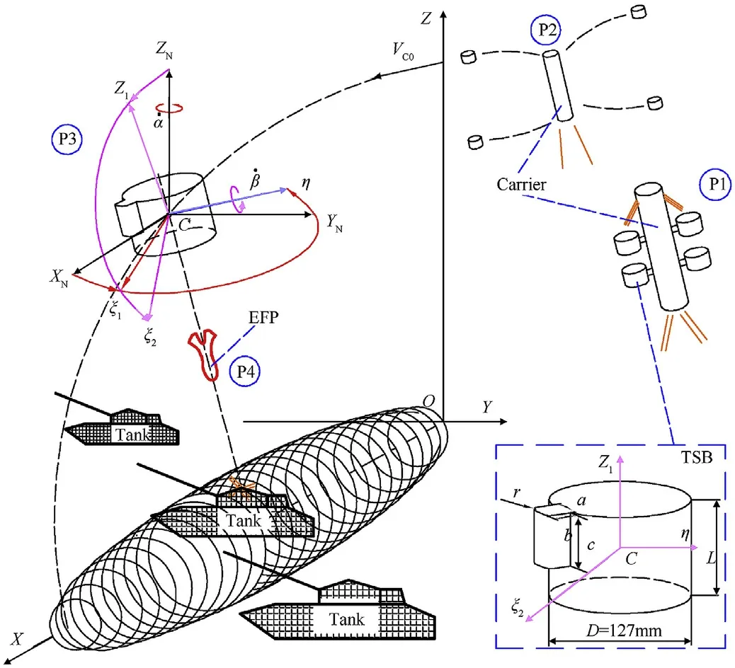
2.The investigation by wind tunnel experiment
2.1.Experiment configurations

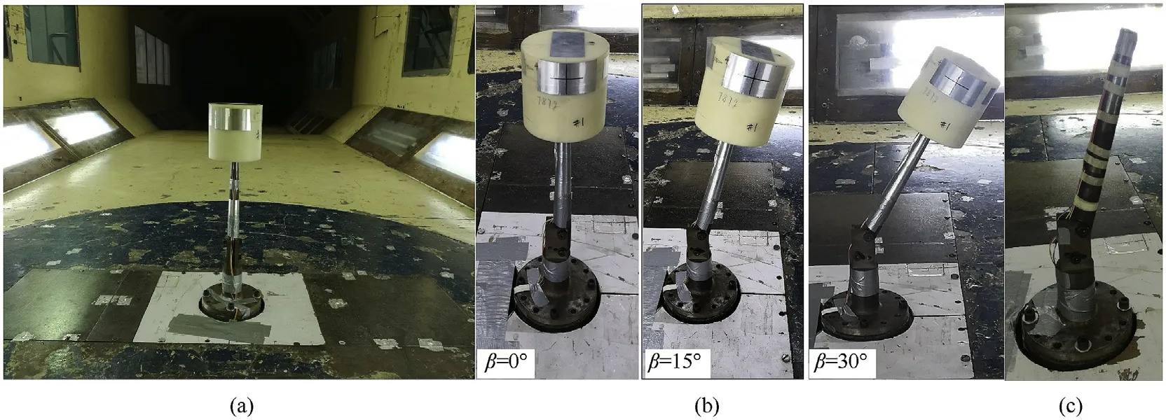
2.2.Results of aerodynamic parameters

3.Numerical research
3.1.Numerical methods
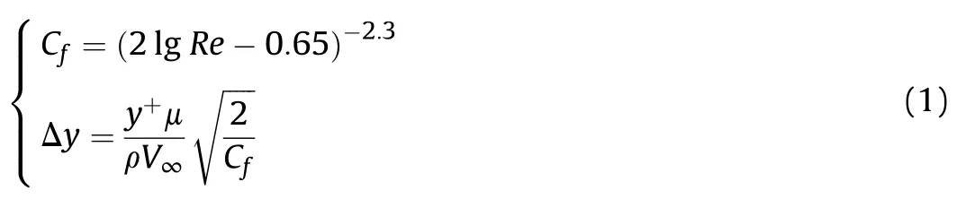
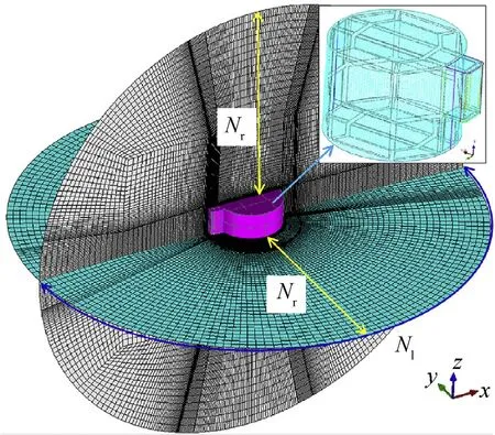
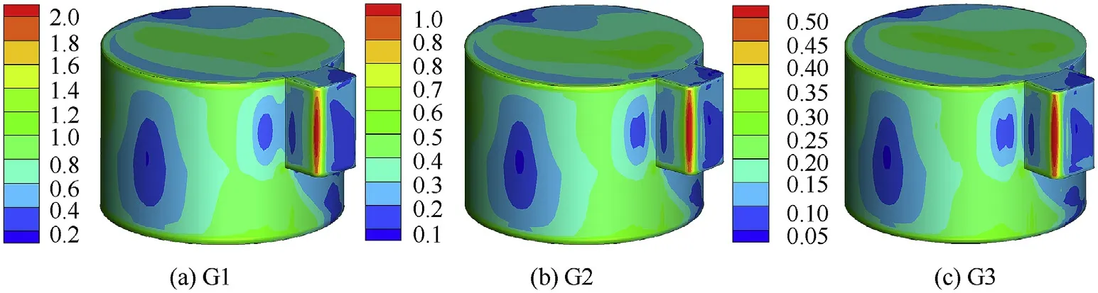
3.2.Sensitivity analysis of grid and time step

3.3.Numerical Experiment configurations
3.4.Numerical verification
4.Results and discussion
4.1.Time-averaged aerodynamic parameters
4.2.Shear layer behavior


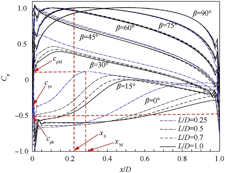
4.3.Quasi-steady time-averaged pressure
4.4.Effect of end’s shape on aerodynamic characteristics

5.Conclusion
杂志排行

Defence Technology的其它文章
- Ricochet quantification using a multiple sensor approach☆
- Reaction degree of composition B explosive with multi-layered compound structure protection subjected to detonation loading
- Effects of nano-sized aluminum on detonation characteristics and metal acceleration for RDX-based aluminized explosive
- Increasing of photostability of HNS explosive in the presence of UV photostabilizers
- Numerical investigation on cooling performance of filter in a pyrotechnic gas generator
- Decision support model for effects estimation and proportionality assessment for targeting in cyber operations