Hierarchical Magnetic Network Constructed by CoFe Nanoparticles Suspended Within “Tubes on Rods” Matrix Toward Enhanced Microwave Absorption
2021-03-08ChunyangXuLeiWangXiaoLiXiangQianZhengchenWuWenbinYouKePeiGangQinQingwenZengZiqiYangChenJinRenchaoChe
Chunyang Xu, Lei Wang, Xiao Li, Xiang Qian, Zhengchen Wu, Wenbin You, Ke Pei, Gang Qin, Qingwen Zeng, Ziqi Yang, Chen Jin, Renchao Che
ABSTRACT Hierarchical magnetic‑dielectric composites are prom‑ising functional materials with prospective applications in microwave absorption (MA) field. Herein, a three‑dimension hierarchical “nanotubes on microrods,” core-shell magnetic metal-carbon composite is ration‑ally constructed for the first time via a fast metal-organic frameworks‑based ligand exchange strategy followed by a carbonization treatment with melamine. Abundant magnetic CoFe nanoparticles are embedded within one‑dimensional graphitized carbon/carbon nanotubes supported on micro‑scale Mo2N rod (Mo2N@CoFe@C/CNT), constructing a spe‑cial multi‑dimension hierarchical MA material. Ligand exchange reaction is found to determine the formation of hierarchical magnetic‑dielectric composite, which is assembled by dielectric Mo2N as core and spatially dispersed CoFe nanoparticles within C/CNTs as shell. Mo2N@CoFe@C/CNT composites exhibit superior MA performance with maximum reflection loss of − 53.5 dB at 2 mm thickness and show a broad effective absorption bandwidth of 5.0 GHz. The Mo2N@CoFe@C/CNT composites hold the following advantages: (1) hierarchical core-shell structure offers plentiful of heterojunction interfaces and triggers interfacial polarization, (2) unique electronic migration/hop paths in the graphitized C/CNTs and Mo2N rod facilitate conduc‑tive loss, (3) highly dispersed magnetic CoFe nanoparticles within “tubes on rods” matrix build multi‑scale magnetic coupling network and reinforce magnetic response capability, confirmed by the off‑axis electron holography.
KEYWORDS Hierarchical core-shell MOF‑based composites; CoFe nanoparticles; Magnetic network; Microwave absorption
1 Introduction
Coming into the fifth‑generation (5G) wireless communi‑cation systems, the increasing usage of diverse electronic productions has caused severe electromagnetic radiation pollution, which results in an urgent pursuit for high‑per‑formance microwave absorption (MA) materials [1-9]. Magnetic materials, including metals (Co, Ni, Fe) and metallic alloys (FeCo, NiCo, etc.), are generally used as microwave absorbents due to strong magnetic loss abil‑ity [10-18]. However, practical applications of magnetic materials suffer from their inherent drawbacks: undesir‑able chemical stability, severe aggregation and inferior impedance matching [19-21]. To tackle these obstacles, two typical strategies have been commonly employed to shape MA properties. One is to decorate magnetic compo‑nent with carbon materials to develop magnetic‑dielectric system and thereby boost the MA performance by enhanc‑ing dielectric loss and improving impedance matching [22-31]. For example, Cao et al. designed Fe@NCNTs composite and showed MA performance of − 30.43 dB [32]. Shui et al. prepared CoFe/carbon fiber composite with high MA properties [13]. Tong et al. designed Co/C/Fe/C composite which exhibited significantly improved MA abilities [11]. The other is to construct hierarchical‑structured materials with well‑designed nano‑units, thus achieving high dispersion of magnetic particles and pro‑ducing heterogeneous interface in multicomponent mate‑rials [33-37]. Among various hierarchical structures, the core-shell structures have attracted growing attention in the MA field [38-40] such as Co@C microspheres [10], Fe3O4/C [41], Co@CoO [42], Co20Ni80@TiO2core-shell structure [43]. The delicately designed core-shell com‑posites can satisfy magnetic and dielectric loss simul‑taneously resulting from synergistic effects of different components within both core and shell [44, 45]. Besides, large interspace and heterogeneous interface created by core-shell structure can further enhance polarization loss and strengthen multi‑reflection process [37, 44, 46]. Particularly, hierarchical 1D units assembled core-shell composites exhibit remarkable performance in MA appli‑cation [14, 47, 48]. For example, Che et al. designed hierarchically tubular C/Co composite with abundant 1D nanotubes and achieved highly uniform distribution of Co nanoparticles and outstanding MA performance [49]. Therefore, it is highly desirable to develop a facile and effective preparation strategy to construct magnetic metal-carbon composites with hierarchical core-shell structure.
Metal-organic frameworks (MOFs), with diverse micro‑structure and adjustable composition, have been widely utilized to construct various hierarchical composites [50-54]. MOF‑derived materials demonstrate inherent advantages of abundant metal/carbon components, which endows them with great potential in MA application [40, 55-60]. For example, Ji et al. developed MOF‑derived one‑dimensional sponge‑like metallic Co and Co/C com‑posites with strong magnetic loss [61]. Du et al. presented a MOFs‑derived method to construct hollow Co/C micro‑spheres as microwave absorbents [62]. Zhao et al. pre‑pared hierarchical Fe-Co/N‑doped carbon/rGO compos‑ites derived from Fe‑doped Co‑MOF [63]. However, direct transforming MOFs into microwave absorbents leads to a much lower ratio of metal nanoparticles and poor graphiti‑zation degree of carbon or CNTs, which is unfavorable to the attenuation of microwave. To tackle these problems, the MOF precursor can be further extended by trans‑forming one kind of MOF into another via ion exchange reactions or ligand exchange reactions, introducing more magnetic metals and carbon components. For example, Hu et al. constructed hierarchical bimetallic Co2[Fe(CN)6] hollow structure from a Co‑MOF through ion exchange reactions [64]. This MOF‑to‑MOF strategy inspires us to construct bimetallic MOF‑derived carbon‑based absor‑bents with favorable hierarchical structure, which has rarely been reported in MA field.
Recently, transition metal molybdenum‑based materials, such as MoO2, Mo2C, MoS2and Mo2N, have emerged as effective candidates in the field of electrocatalysis, lithium batteries and supercapacitors due to its low cost, high con‑ductivity and chemical stability [65-72]. Such superior properties also make molybdenum compounds promising microwave absorbents. For example, owing to metallic‑like conductivity of MoO2materials, Huang et al. con‑structed C@MoO2/G composites for efficient MA [73]. Du et al. fabricated ternary Mo2C/Co/C composites for MA [74] and Jin et al. prepared MoS2‑NS with high dielectric properties and MA performances [75]. However, the work of employing Mo2N as microwave absorbent has not been studied so far, although Mo2N materials exhibit satisfied electrical conductivity displaying excellent performance in electrocatalysis and supercapacitors [66, 69]. Therefore, compositing molybdenum compounds into metal-carbon absorbents with designed hierarchical structure is expected to achieve first‑rate MA performance.
Herein, for the first time, a 3D hierarchical “nanotubes on microrods” core-shell composite of magnetic CoFe nan‑oparticles suspended within one‑dimensional graphitized C/CNTs supported on Mo2N rod (Mo2N@CoFe@C/CNT) is successfully achieved through a fast MOF‑based ligand exchange strategy. The intermediate product of MoO3@hollow‑CoFe‑PBA composite plays an important role in not only providing Fe source for the growth of CoFe alloy and C/CNTs but also constructing hierarchical core-shell structure in final composite, thus achieving highly disper‑sive distribution of magnetic particles. The unique Mo2N@CoFe@C/CNT composite holds the dielectric Mo2N as core and magnetic CoFe nanoparticles embedded C/CNTs as shell. Such 3D hierarchical magnetic network assem‑bled by CoFe nanoparticles suspended within “tubes on rods” matrix demonstrates strong magnetic loss capabil‑ity, which can be verified by off‑axis electron holography. Besides, numerous Mo2N rods and graphitized CNTs in the composite constitute dual conductive network to facilitate conductive loss. Moreover, large interfaces in hierarchical core-shell structure can trigger intensive polarization loss. Our hierarchical Mo2N@CoFe@C/CNT composite dem‑onstrates superior MA performance with maximum reflec‑tion loss value of − 53.5 dB at the thickness of only 2 mm thickness and the effective absorption bandwidth can reach 5.0 GHz. Therefore, the presented fast MOF‑based ligand exchange strategy provides an effective method to fabricate multicomponent absorbents with well‑controlled hierarchi‑cal structure for achieving excellent MA properties.
2 Experimental Section
2.1 Materials
All chemicals used were of analytical grade and were used directly without further purification. All chemicals were purchased from Sinopharm Chemical Reagent Co., Ltd.
2.2 Synthesis of MoO3
In a typical synthesis, 0.5793 g ammonium molybdate tet‑rahydrate was dissolved in 30 mL of deionized (DI) water; then, 2.5 mL of HNO3was added. The solution was kept stirring for 10 min, then transferred into a Teflon‑lined stainless autoclave (50 mL) and kept at 180 °C for 12 h. When the temperature of Teflon‑lined stainless autoclave was cooled naturally, the precipitate was collected and washed repeatedly with DI water for at least three times before drying at 70 °C.
2.3 Synthesis of MoO3@Co‑MOF
First, the solution A was prepared by 50 mg of MoO3and 0.582 g CoNO3·6H2O were dissolved in 20 mL of metha‑nol. Then solution B was prepared by dispersing 1.3132 g of 2‑methylimidazole in 20 mL of methanol. The solution B was added into solution A under stirring and kept stir‑ring for 5 min then aged for 20 min at room temperature. The precipitate was collected and washed with ethanol for at least three times and dried at 70 °C.
2.4 Synthesis of MoO3@hollow‑CoFe‑PBA
40 mg of MoO3@Co‑MOF was dissolved in 10 mL ethanol to get solution C. 40 mg of K3[Fe(CN)6] was dissolved in 20 mL DI water and 20 mL ethanol to get solution D. Then solution D was poured into solution C under stirring and kept stirring for 5 min. The precipitate was collected and washed with DI water and dried at 70 °C.
2.5 Synthesis of Mo2N@CoFe@C/CNT
In a typical synthesis, 0.1 g of as‑prepared MoO3@hollow‑CoFe‑PBA and 0.5 g of melamine were placed separately in a quartz boat where the melamine was placed at upstream side of the furnace. The furnace was heated to 600 °C at a rate of 2 °C min−1for 4 h under a hydrogen/argon atmos‑phere. Finally, Mo2N@CoFe@C/CNT composite was obtained after cooling down to ambient temperature.
2.6 Synthesis of Mo2N and Mo2N@Co/CNT
For comparison, Mo2N and Mo2N@Co/CNT were synthe‑sized by calcining the MoO3and MoO3@Co‑MOF with melamine, respectively.
2.7 Microwave Absorption Measurements
The measured samples were first prepared by adding the absorbents (20 wt%) into molten paraffin and uniformly mix‑ing them, followed by modeling into a coaxial ring with the outer diameter of 7.0 mm and inner diameter of 3.0 mm. Electromagnetic parameters (complex permittivity and complex permeability) were measured by a N5230C vector network analyzer over the range of 2-18 GHz. The reflec‑tion loss values were calculated based on the transmission line theory:
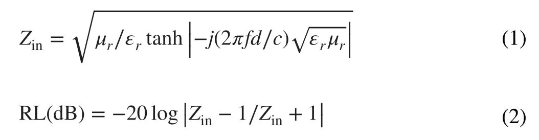
whereεrandµrare the complex permittivity (εr=ε′−jε′′) and permeability (µr=µ′−jµ′′), respectively,fis the fre‑quency of microwave,cis the velocity of light,dis the thickness, andZinis the normalized input impedance of the sample.
2.8 Characterizations
The crystalline phase and purity of the products was analyzed by powder X‑ray diffraction (XRD, Bruker, D8‑Advance X‑ray diffractometer, Germany) using Ni‑filtered Cu Ka radiation. The morphology and structure of the products were examined by a field‑emission scan‑ning electron microscopy (SEM) on a Hitachi S‑4800 with an accelerating voltage of 5 kV and a field‑emission trans‑mission electron microscope (TEM, JEOL, JEM‑2100F, 200 kV). The Raman spectra were acquired with a Renishaw Invia spectrometer using a 514 nm laser excitation. X‑ray photoelectron spectroscopy (XPS) spectra were obtained on an ESCALab MKII X‑ray photoelectron spectrometer using Al Kα X‑ray as the excitation source. The hysteresis loops were performed with a superconducting quantum interfer‑ence device (MPMS(SQUID) VSM) magnetometer (Quan‑tum Design Company).
3 Results and Discussion
3.1 Fabrication and Characterization of Mo2N@CoFe@C/CNT Composites
The synthesis of the hierarchical Mo2N@CoFe@C/CNT core-shell structure is illustrated in Fig. 1. First, the Co‑MOF is uniformly grown on MoO3rod to form MoO3@Co‑MOF structure. Second, through a fast ligand exchange reaction with K3[Fe(CN)6] in 5 min at room tempera‑ture, MoO3@Co‑MOF structure is in situ converted into MoO3@hollow‑CoFe‑PBA core-shell composite. Followed by the carbonization of MoO3@hollow‑CoFe‑PBA with melamine, the inner MoO3is transformed into Mo2N rod and the outer hollow‑CoFe‑PBA turn into the CoFe@C/CNTs architecture, where thermally reduced CoFe nano‑particles could catalyze the growth of graphitic carbon and CNTs with melamine as carbon source. Finally, the hier‑archical Mo2N@CoFe@C/CNT composite with “tubes on rods” structure is successfully obtained. Moreover, through fast ligand exchange reaction, the intermediate product of MoO3@hollow‑CoFe‑PBA core-shell structure plays a critical role in the formation of hierarchical Mo2N@CoFe@C/CNT composite, which will be explained in the following discussion.

Fig. 1 Schematic process of the fast MOF‑based ligand exchange strategy for construction of 3D hierarchical Mo2N@CoFe@C/CNT compos‑ites
As displayed in Fig. S1, as‑prepared uniform MoO3rods demonstrate smooth surface and high phase purity. Then MoO3rods are covered with Co‑MOF to form MoO3@Co‑MOF structure. The SEM images reveal that the sur‑face of MoO3rods becomes rough (Fig. 2a). The core of MoO3and shell of Co‑MOF can be clearly observed in TEM images (Fig. 2b, c). And both diffraction peaks of MoO3and Co‑MOF are well detected in XRD pattern (Fig. S2), indicating that Co‑MOF is successfully grown on the MoO3rods. To construct hollow CoFe‑PBA on the MoO3rods, the MoO3@Co‑MOF samples are kept in K3[Fe(CN)6] solution and stirred for just 5 min at room temperature to allow the ligand exchange reaction to pre‑pare MoO3@hollow‑CoFe‑PBA structure. Firstly, the MoO3@Co‑MOF will slowly decompose in water/etha‑nol to release Co2+ions. Then the [Fe(CN)6]3−ions are injected into the reaction solution. The released Co2+ions can interact with [Fe(CN)6]3−ions to generate CoFe‑PBA shell around the framework of the precursors (Co‑MOF). Finally, the solid Co‑MOF shell is completely converted into hollow CoFe‑PBA, and MoO3@hollow‑CoFe‑PBA core-shell composites are obtained. As displayed in Fig. 2d, the rather rough CoFe‑PBA is grown on the MoO3rods and some holes can be seen on the surface (as dis‑played in the yellow circles of Fig. 2d). Such unique shell of hollow CoFe‑PBA can be further confirmed by TEM images. In Fig. 2e, f, the as‑prepared MoO3@hollow‑CoFe‑PBA structure is consisted of the nanocage‑assem‑bled CoFe‑PBA shell and the MoO3core. XRD result also demonstrates that the sample is composed of MoO3and Co2[Fe(CN)6] (Fig. S3) [64]. Such core-shell of MoO3@hollow‑CoFe‑PBA composite plays a significant role not only in providing the Fe source for the growth of CoFe alloys and CNTs but also in constructing the core-shell structure in the final multicomponent products. Subse‑quently, the MoO3@hollow‑CoFe‑PBA composite is converted into Mo2N@CoFe@C/CNT core-shell struc‑ture through the carbonization with melamine. For com‑parison, Mo2N rod and Mo2N@Co/CNT samples are also synthesized by calcining the MoO3and MoO3@Co‑MOF composite with melamine, respectively.
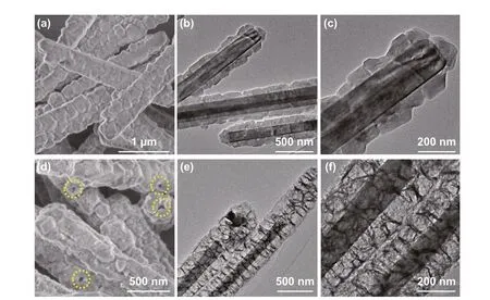
Fig. 2 a SEM, b, c TEM images of MoO3@Co‑MOF, d SEM, e, f TEM images of MoO3@hollow‑CoFe‑PBA composites
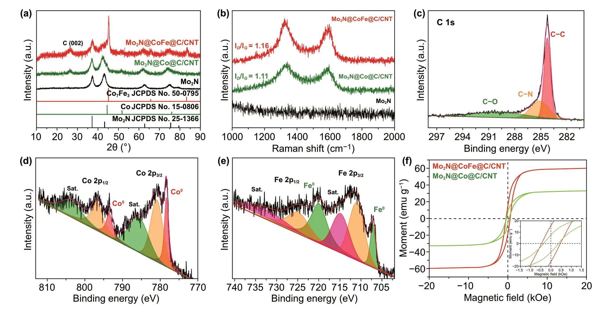
Fig. 3 a XRD patterns, b Raman spectra of as‑prepared Mo2N, Mo2N@Co/CNT and Mo2N@CoFe@C/CNT. High resolution XPS spectra of c C 1s, d Co 2p, and e Fe 2p for Mo2N@CoFe@C/CNT composite. f hysteresis loops of Mo2N@Co/CNT and Mo2N@CoFe@C/CNT composites
The chemical compositions of Mo2N rod, Mo2N@Co/CNT, and Mo2N@CoFe@C/CNT composites are measured by XRD, Raman and XPS techniques. As dis‑played in Fig. 3a, the diffraction peaks of Mo2N rods are in accordance with reflections of molybdenum nitride (Mo2N, JCPDS No. 25‑1366) while the Mo2N@Co/CNT samples exhibit diffraction peaks of both Mo2N and cubic cobalt (JPCDS No. 15‑0806). In the XRD pattern of Mo2N@CoFe@C/CNT composites, apart from char‑acteristic peaks of Mo2N, a diffraction peak at 26.1ocan be observed clearly, attributing to the (002) plane of the graphitic carbon. Other peaks at around 45.2o, 65.8o, and 83.3omatch well with diffractions of the cubic cobalt iron (JPCDS No. 50‑0795). Above‑mentioned XRD results demonstrate that the Mo2N@CoFe@C/CNT composite is consisted of Mo2N, CoFe alloy and graphitic carbon. To reveal the graphitic feature and structural defects of as‑prepared samples, Raman spectra are conducted. In Fig. 3b, the Mo2N@CoFe@C/CNT composite exhibits the highestID/IGvalue of 1.16 because a great number of defects are produced in such core-shell structure. The value ofID/IGis increased with more CNTs catalyzed by the CoFe alloy compared with less graphitic carbon by single metal Co in Mo2N@Co/CNT sample, which could promote the electronic transportation ability. Chemical valence states of Mo2N@CoFe@C/CNT are examined via XPS technique. In Fig. 3c, three peaks of C 1sspectrum correspond to the C-C (284.28 eV), C-N (285.16 eV) and C-O (189.73 eV) [76]. In the Co 2pspectrum, peaks at 778.32 and 793.44 eV are ascribed to Co0in Co 2p3/2and Co 2p1/2and peaks at 780.82 and 796.67 eV belong to Co2+species. In Fig. 3e, the Fe 2pspectrum can be decomposed into two peaks of 707.22 eV for Fe02p3/2and 719.97 eV for Fe02p1/2and other two peaks of 711.06 and 724.85 eV for Fe2+2p3/2and 2p1/2, respectively [63, 77-79]. The bimetal CoFe with multiple valency in Mo2N@CoFe@C/CNT sample could result in higher saturation magnetization. As shown in Fig. 3f, the saturation magnetization (Ms) value of Mo2N@CoFe@C/CNT is 59.6 emu g−1, which is higher than that of Mo2N@Co/CNT sample. And the coercivity value is 449.6 Oe for Mo2N@CoFe@C/CNT composite. Such high saturation magnetization and low coercivity of Mo2N@CoFe@C/CNT hierarchical structure could boost magnetic storage and reinforce magnetic loss, further pro‑moting MA performance [57, 80].

Fig. 4 a–c SEM, d–f TEM images of Mo2N@CoFe@C/CNT composites
The morphology and structure of Mo2N rod, Mo2N@Co/CNT and Mo2N@CoFe@C/CNT core-shell compos‑ites are further performed with SEM and TEM images. As displayed in Fig. 4, a large number of CNTs are produced and deposited on the core of Mo2N rod which can be clearly observed in Fig. 4a-c with yellow arrows. In the follow‑ing TEM images, the rod‑like core is seen and wrapped by outer shell of numerous CNTs. Particularly, the obvious void exists between the shell and core (Fig. 4d-f) and the CNTs are not directly grown on the Mo2N rod but supported by the shell of CoFe alloy embedded graphitic carbon layers. Such uniquely hierarchical Mo2N@CoFe@C/CNT core-shell structure is reported for the first time and can be further confirmed by the magnified TEM and HRTEM images. Abundant CNTs can be seen and on the top of each CNT is encapsulated metal nanoparticles, which are wrapped by numbers of graphitic carbon layers (Fig. 5a-d). In Fig. 5e, the HRTEM image obtained from the shell of such Mo2N@CoFe@C/CNT structure (as marked in Fig. 5a with yellow square) demonstrates that the interplanar spacing of 0.20 nm can correspond to the (110) plane of CoFe alloy and 0.34 nm to the (002) plane of graphitic carbon, which convincingly confirms such unique shell of CoFe nanoparticles embedded graphitic carbon. The corresponding selected area electron diffraction pattern displays a series of diffraction rings which can be well indexed to diffraction planes of crystalline Mo2N and CoFe alloy (Fig. 5f). Clearly, based on the above results of morphology and composition, hierarchical Mo2N@CoFe@C/CNT “tubes on rods” architecture is successfully synthesized through a fast MOF‑based ligand exchange strat‑egy. In the calcinating process of MoO3@hollow‑CoFe‑PBA composite with melamine, the MoO3is converted into the core of Mo2N rod and hollow‑CoFe‑PBA is transformed into the shell of CoFe alloy embedded C/CNTs with thermally reduced CoFe nanoparticles as catalysts and melamine as carbon source. For comparison, Mo2N@Co/CNT sample is obtained by directly annealing MoO3@Co‑MOF composite with melamine. As shown in Fig. S4, the Mo2N@Co/CNT composites maintain the rod structure but only few of CNTs are observed on the surface of Mo2N rod without the shell of metal‑embedded graphitic carbon framework. This evidence suggests that single Co nanoparticles could not effectively catalyze the growth of CNTs. Obviously, MoO3@hollow‑CoFe‑PBA structure constructed by ligand exchange reac‑tion critically determines the formation of CoFe nanoparti‑cles, graphitic C/CNTs and hierarchical core-shell structure. Rod‑like Mo2N are prepared through annealing MoO3rods with melamine, which displays uniformly smooth rod struc‑ture (Fig. S5). Remarkably, as‑prepared hierarchical Mo2N@CoFe@C/CNT can be considered as both distinct conductive structure and magnetic network, which hold great potential to achieve superior MA ability.
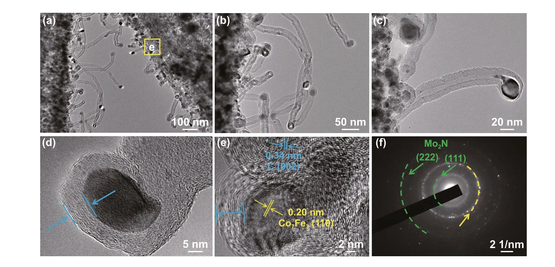
Fig. 5 a–c The magnified TEM, d–e HRTEM images and f corresponding selected area electron diffraction of Mo2N@CoFe@C/CNT compos‑ites
3.2 Electromagnetic Parameters Analysis and Microwave Absorption Ability
Related electromagnetic parameters of as‑prepared Mo2N@CoFe@C/CNT, Mo2N@Co/CNT and Mo2N samples are investigated to reveal the impacts of structure and composi‑tion on the MA performance. Generally, MA properties are highly determined by the complex permittivity and complex permeability of materials. It is acknowledged that the real parts of complex permittivity (ε′) and complex permeabil‑ity (μ′) indicate the capability of storing electromagnetic energy, while the imaginary parts (ε″, μ″) imply the ability to loss electromagnetic energy. As shown in Fig. S8, the pure Mo2N sample displays real permittivity (ε′) ranging from 12.06 to 10.92, suggesting the Mo2N is a better dielectric material. And the ε′ values of Mo2N@Co/CNT samples rise obviously from 19.40 to 12.76 due to the introduction of conductive CNTs. When more CoFe alloy embedded CNTs and graphitic carbon layers are introduced, the ε′ values of Mo2N@CoFe@C/CNT sample range from 10.2 to 5.6 with the increase in frequency, demonstrating Mo2N@CoFe@C/CNT materials gain strong capability of energy storage and high dielectric polarization. And the ε″ values of Mo2N@CoFe@C/CNT also remain high from 3.78 to 2.56, which means a powerful dielectric loss ability. This can be ascribed to the hierarchical conductive network and enhanced interfa‑cial polarization resulting from unique core-shell structure of dielectric Mo2N and conductive C/CNTs components. To further evaluate the dielectric loss property, the dielectric loss tangentδε(tanδε=ε″/ε′) was calculated. It is believed that higher tanδεvalue means more electric energy of inci‑dent microwaves would be dissipated. As shown in Fig. S9a, the tanδεvalues of Mo2N@CoFe@C/CNT remain high, which offers the convincing evidence that the design of hierarchically core-shell structure with the combination of dielectric Mo2N and graphitic C/CNTs components is an effective way to enhance the dielectric loss capacity. As for the real (µ′) and imaginary (µ″) parts of permeability, theµ′ andµ″ values of Mo2N remain close to 1 and 0 due to its nonmagnetic property. Compared with Mo2N@Co/CNT samples, theµ′ andµ″ of Mo2N@CoFe@C/CNT are higher because of its enhanced magnetic CoFe alloy component and hierarchical 3D magnetic network. Therefore, the Mo2N@CoFe@C/CNT material is prone to generate favorable mag‑netic loss capability. Based on above discussion, as‑prepared Mo2N@CoFe@C/CNT composite is expected to exhibit superior MA capability originating from its both synergetic strong dielectric dissipation and magnetic loss.
The MA performance of absorbents is generally evalu‑ated with the maximum reflection loss (RL) value and effec‑tive absorption bandwidth. Figure 6 displays the 3D plots ofRLvalues on different thickness of Mo2N, Mo2N@Co/CNT and Mo2N@CoFe@C/CNT samples. The Mo2N rods exhibit good MA performance with the maximumRLvalue of − 25.9 dB at the thickness of 4.5 mm (Fig. 6a) due to its high dielectric property. With the introduction of Co/CNTs components, the Mo2N@Co/CNT materials exhibit MA with the maximumRLvalue of − 34.8 dB. Significantly, as displayed in Fig. 6c, the Mo2N@CoFe@C/CNT demon‑strates the best MA performance with highest maximumRLvalue of − 53.5 dB at the thickness of only 2 mm thickness, and the effective absorption bandwidth can reach 5 GHz (from 12 to 17 GHz). Moreover, while tuning the thickness from 1.5 to 5.0 mm, Mo2N@CoFe@C/CNT samples still exhibit impressive MA performance with the maximumRLvalues all less than − 10 dB, revealing its tunable MA abil‑ity. These encouraging results demonstrate that as‑prepared Mo2N@CoFe@C/CNT composites hold excellent MA per‑formance owing to its strong microwave energy absorption, broad effective absorption bandwidth, lower thickness and tunable absorption frequency, which is superior to those reported metal/carbon microwave absorbents (Table S1).
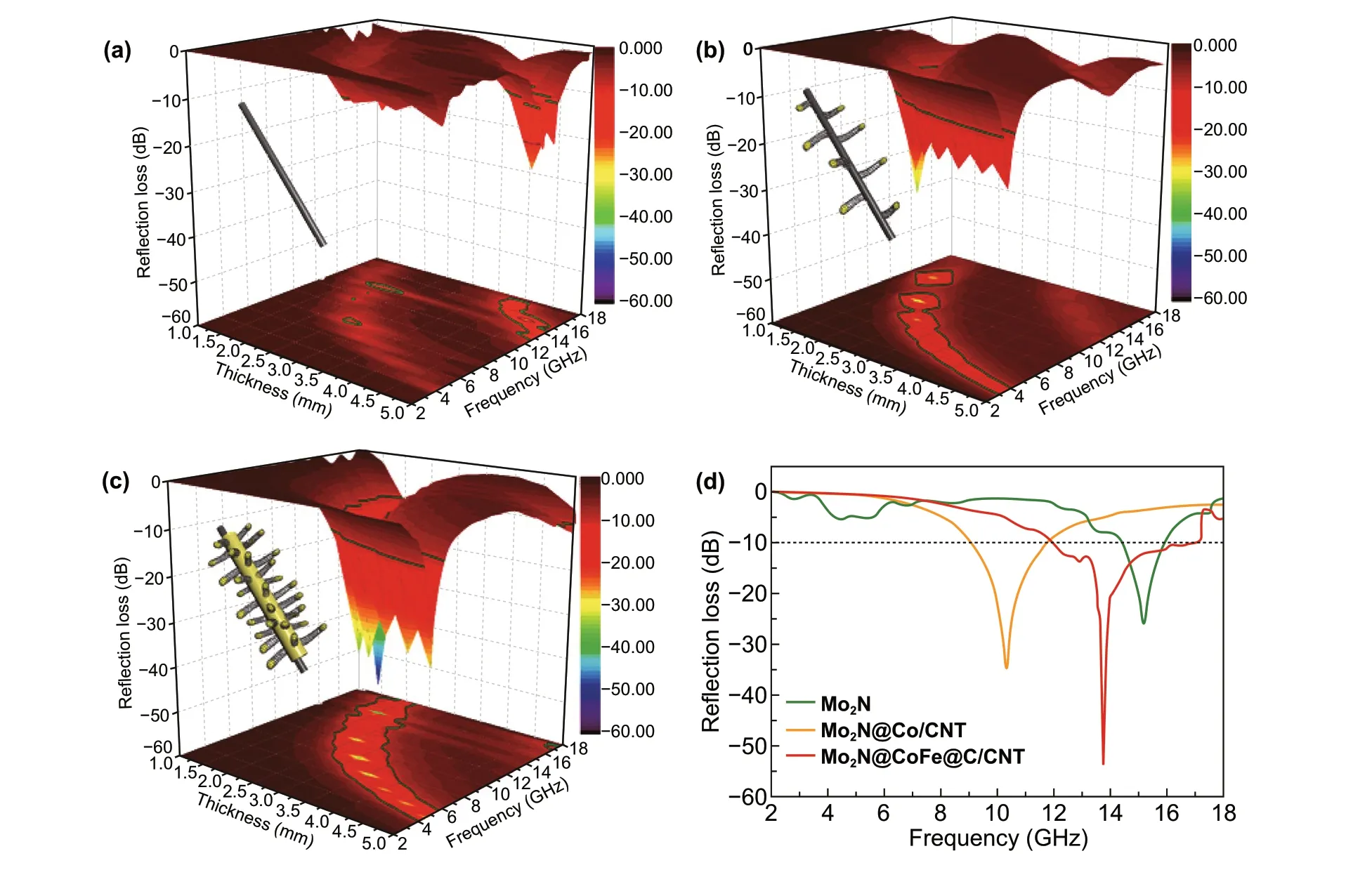
Fig. 6 3D plots of reflection loss of a Mo2N, b Mo2N@Co/CNT and c Mo2N@CoFe@C/CNT samples. d Reflection loss curves at the same thickness of 2 mm
3.3 Analysis of Microwave Absorption Mechanism
Accordingly, the rational design of 3D hierarchical core-shell structure of Mo2N@CoFe@C/CNT absorber and the combination of dielectric Mo2N, conductive C/CNTs and magnetic CoFe alloy components contribute to the enhancement of electromagnetic storage and MA per‑formance. Related microwave energy absorption/conversion mechanisms of MA can be illustrated as followed in detail (Fig. 7).
3.3.1 Multiple Heterojunction Interfaces and Hierarchical Electronic Transportation Paths Boosted Dielectric Loss
3D assembly Mo2N@CoFe@C/CNT composites possess plentiful heterojunction interfaces, which is necessary to the improvement of dielectric storage ability and polarization behaviors. Hierarchical Mo2N@CoFe@C/CNT composite is made up of dielectric Mo2N, graphitized C/CNTs and mag‑netic CoFe nanoparticles. In such “tubes on rods” matrix, there are at least three kinds of heterojunction interfaces, including CoFe‑CNTs interfaces, graphitized carbon-CNTs interfaces and graphitized carbon-Mo2N interfaces (Fig. 7c). Due to differences in electrical conductivity among compo‑nents, free electrons gather around those contacting inter‑faces when applied variation of electromagnetic wave. This electronic migration/moment can produce intensive interfa‑cial polarization and relaxation causing the conversion from electromagnetic waves energy into thermal energy. Besides, numerous carbon heteroatoms groups (such as C‑N and C‑O, Fig. 3c) in Mo2N@CoFe@C/CNT could be regarded as active dipole sites. Related dipole polarization can also improve the MA performance. Therefore, Mo2N@CoFe@C/CNT composite exhibits higher dielectric polarization abil‑ity compared with Mo2N@Co/CNT and Mo2N materials owing to its multiple interfaces and multicomponent. In addition, both dielectric Mo2N rod and graphitized C/CNTs can be also considered as a conductive network. Micro‑scale Mo2N rod displays high permittivity. When graphitized C/CNTs grow on Mo2N rod, numerous electronic transpor‑tation routes are formed between C/CNTs and Mo2N rod (Fig. 7a, b). This conduction transportation network facili‑tates enhanced conduction loss capability, which is also favorable for MA performance.
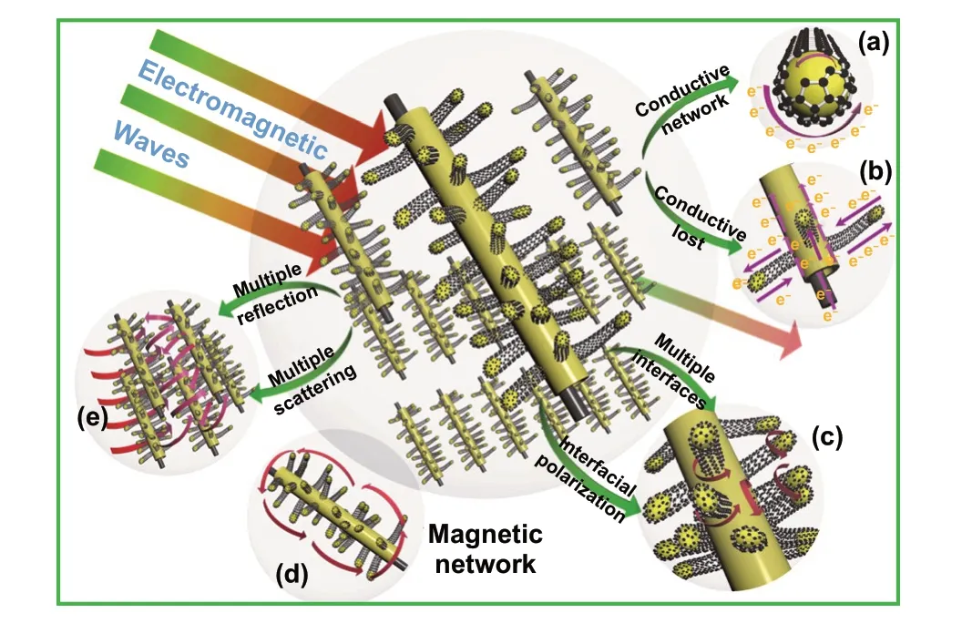
Fig. 7 The microwave absorption mechanism in the 3D hierarchical Mo2N@CoFe@C/CNT composites
3.3.2 Spatial Dispersed CoFe Nanoparticles Built Multi‑scale Magnetic Coupling Network
Spatial dispersed nano‑scale CoFe alloy suspended within hierarchical micro‑scale Mo2N@C/CNTs rod construct a multi‑scale magnetic network and could significantly contribute to the boosted magnetic responding capacity (Fig. 7d). Traditionally, magnetic nanoparticles could eas‑ily aggregate together due to their magnetic nature. Metal aggregation problem can hardly be avoided in the process of pyrolyzing MOFs directly. Herein, through our ligand exchange strategy, as‑synthesized MoO3@hollow‑CoFe‑PBA structure can not only effectively reduce the aggrega‑tion of magnetic nanoparticles but also expand spatial mag‑netic distribution, thereby further increasing the responding scale of magnetic component in the final Mo2N@CoFe@C/CNT composite. As‑fabricated hierarchical Mo2N@C/CNT architecture provides a perfect nano/micro‑matrix to support suspended CoFe nanoparticles (Figs. 4 and 5), thus forming a distributed magnetic network and strengthening magnetic permeability. The off‑axis electron holography is performed to study the magnetic property of CoFe nanoparticles and related magnetic network in Mo2N@CoFe@C/CNT com‑posite. As shown in Fig. 8a-c, the CoFe nanoparticles in the composite can radiate out high‑density magnetic lines which could penetrate through the nonmagnetic graphitic C/CNTs and expand magnetic responding regions beyond itself size. Furthermore, the neighbored CoFe nanoparticle sus‑pended within C/CNTs matrix displays magnetic coupling lines which could contribute to integral magnetic network, further strengthen magnetic dissipation capacity (Fig. 8d-f) [49]. Meanwhile, high loading and uniformly distribution of CoFe nanoparticles (Fig. 5) can also enhance the magnetic loss to promote MA performance. Therefore, compared with Mo2N@Co/CNT and other magnetic metal/carbon compos‑ites reported previously, hierarchical Mo2N@CoFe@C/CNT composite can successfully avoid magnetic metal aggrega‑tion problem and exhibit remarkable magnetic loss property.
3.3.3 Synergic Magnetic‑dielectric MA System and Multi‑dimension Hierarchical Structure
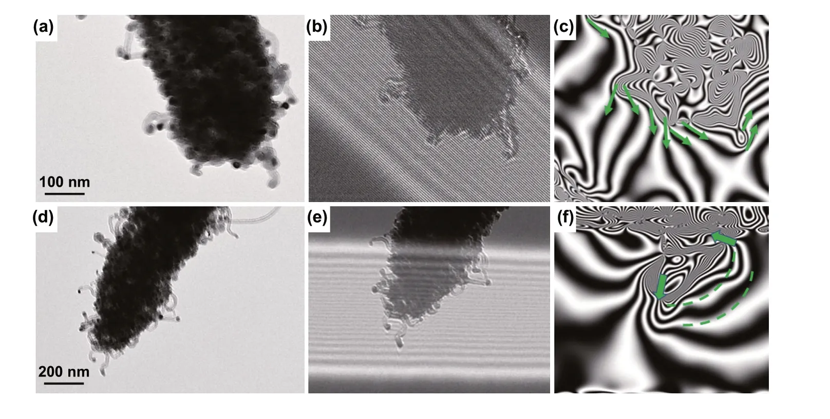
Fig. 8 a, d TEM images and b–c, e–f corresponding off‑axis electron holograms of Mo2N@CoFe@C/CNT composites
Hierarchical Mo2N@CoFe@C/CNT composites can effectively dissipate the microwave energy via dielectric dissipation and magnetic loss. The assembled composite is constructed by dielectric Mo2N as core and spatially dispersed CoFe nanoparticles within C/CNTs as shell and thus demonstrate significantly improved MA performance resulting from both dielectric loss and magnetic loss, com‑pared with single Mo2N material or Mo2N@Co/CNT com‑posite with few metal nanoparticles. Meanwhile, because of the hierarchical structure and multi‑scale size, Mo2N@CoFe@C/CNT assembly possess unique multi‑reflection and multi‑scattering (Fig. 7e). Abundant 1D CNTs, micro‑scale Mo2N rod and 3D hierarchical core-shell structure could generate effective surface area and spacing effect. When incidence microwave permeates into this 3D archi‑tecture, expected large surface areas offer many active sites to produce multiple reflection and scattering. Such repeated reflection and scattering process of incident microwave can successfully attenuate microwave energy. Benefiting from above advantages of hierarchical structure and multi‑loss mechanism, as‑prepared Mo2N@CoFe@C/CNT compos‑ites exhibit superior MA performance that surpass those reported metal-carbon microwave absorbents (Table S1).
4 Conclusion
In conclusion, as‑prepared Mo2N@CoFe@C/CNT com‑posites exhibit superior MA performance with maximum reflection loss value of − 53.5 dB at the thickness of only 2 mm thickness and a broad effective absorption band‑width of 5 GHz. Such 3D hierarchical core-shell structure assembled by nano‑scale magnetic CoFe nanoparticles sus‑pended within graphitic C/CNTs supported on micro‑scale Mo2N rod is rationally constructed via our effective ligand
exchange strategy. The dielectric Mo2N and C/CNTs com‑ponents can shape strong conductive loss and hierarchical core-shell structure offers large interfacial area to trigger polarization loss. Moreover, distributed magnetic CoFe nanoparticles embedded in C/CNTs matrix form multi‑scale magnetic network and reinforce magnetic response capabil‑ity, which is verified by the off‑axis electron holography. Firmly, the MOF‑based ligand exchange strategy in this work can be utilized to construct various hierarchical struc‑ture of multicomponent metal-carbon system for enhanced MA performance.
AcknowledgementsThis work was supported by the Min‑istry of Science and Technology of China (973 Project No. 2018YFA0209102) and the National Natural Science Foundation of China (11727807, 51725101, 51672050, 61790581).
Open AccessThis article is licensed under a Creative Commons Attribution 4.0 International License, which permits use, sharing, adaptation, distribution and reproduction in any medium or format, as long as you give appropriate credit to the original author(s) and the source, provide a link to the Creative Commons licence, and indicate if changes were made. The images or other third party material in this article are included in the article’s Creative Com‑mons licence, unless indicated otherwise in a credit line to the material. If material is not included in the article’s Creative Com‑mons licence and your intended use is not permitted by statutory regulation or exceeds the permitted use, you will need to obtain permission directly from the copyright holder. To view a copy of this licence, visit http://creat iveco mmons.org/licen ses/by/4.0/.
Electronic supplementary materialThe online version of this article (https://doi.org/10.1007/s4082 0‑020‑00572‑5) contains supplementary material, which is available to authorized users.
杂志排行
Nano-Micro Letters的其它文章
- Cu3(PO4)2: Novel Anion Convertor for Aqueous Dual‑Ion Battery
- Solution‑Processed Transparent Conducting Electrodes for Flexible Organic Solar Cells with 16.61% Efficiency
- High‑Energy and High‑Power Pseudocapacitor–Battery Hybrid Sodium‑Ion Capacitor with Na+ Intercalation Pseudocapacitance Anode
- Chemical Coupled PEDOT:PSS/Si Electrode: Suppressed Electrolyte Consumption Enables Long‑Term Stability
- Metallic Graphene Nanoribbons
- Armoring Black Phosphorus Anode with Stable Metal–Organic‑Framework Layer for Hybrid K‑Ion Capacitors