Study of Array Antenna Pattern Synthesis Based on Sparse Sensing
2021-01-08TingWangYiDongGuofengShaoandFanWang
Ting Wang, Yi Dong, Guofeng Shao and Fan Wang
(1. School of Electronic Information Engineering, Hebei University of Technology, Tianjin 300401, China;2. People’s Liberation Army Air Force 93756, Tianjin 300131, China)
Abstract: Aiming at the problem that a large number of array elements are needed for uniform arrays to meet the requirements of direction map, a sparse array pattern synthesis method is proposed in this paper based on the sparse sensing theory. First, the Orthogonal Matching Pursuit (OMP) algorithm and the Exact Augmented Lagrange Multiplier (EALM) algorithm were improved in the sparse sensing theory to obtain a more efficient Orthogonal Multi-Matching Pursuit (OMMP) algorithm and the Semi-Exact Augmented Lagrange Multiplier (SEALM) algorithm. Then, the two improved algorithms were applied to linear array and planar array pattern syntheses respectively. Results showed that the improved algorithms could achieve the required pattern with very few elements. Numerical simulations verified the effectiveness and superiority of the two synthetic methods. In addition, compared with the existing sparse array synthesis method, the proposed method was more robust and accurate, and could maintain the advantage of easy implementation.
Keywords: array antenna; compressed sensing; low rank matrix recovery; Exact Augmented Lagrange Multiplier algorithm
1 Introduction
In wireless communication system, antenna is usually adopted to receive radio waves and can transfer information between locations without any equipment in the middle. Antenna array pattern synthesis is the technology that the characteristics of antennas are changed to meet the requirements of the antenna by using multiple optimization algorithms, which plays a vital role in the fields of traditional antenna and smart antenna. In the research of pattern synthesis of homogeneous array, numerous algorithms for low sidelobe pattern synthesis in homogeneous linear array have been proposed by Dolph[1], Taylor[2]and other scholars. In the same research area, different kinds of self-adaptive algorithms were proposed ,such as LMS[3],SMI[4],RLS[5]and so on. However, there is an obligation of sufficient homogeneous array elements to achieve the requirements of antenna in these studies, which significantly increases the complexity and the cost of equipment.
In the design of antenna array, the method of sparse array has been utilized to construct an antenna array of low-gain and strong-directivity to meet the requirements of antenna with fewer elements and substantially reduce production cost[6-9].
As early as the 1960s, some researchers carried out considerable research on the problem of non-uniform arrays and sparse arrays. Harrington[10]obtained a lower sidelobe level than a uniform array of the same array elements by optimizing the element position. Andreasen[11]demonstrated the relation of sidelobe level with the number of array elements and the average array spacing. Later, Steinberg[12]made a summary of random arrays and aperiodic arrays in his work. Domestically, Zhang Yuhong[13]of Xidian University deduced an optimal array element distribution equation based on the work of Ishimaru. The equation comprehensively analyzes the sidelobe level and the estimation problem of the exponentially spaced array over the entire viewing area, and the lower limit of the peak sidelobe level of the sparse array and the estimation formula of beam width is theoretically derived.
New methods have sprung up over the years. In 2008, based on matrix pencil method (MPM), Liu proposed a sparse array synthesis method and applied it for one-dimensional linear array synthesis[14]. Since 2011, Prisco[15]of the Italy ELEDIA research center and Fuchs[16]of Ryan University in France drew on the latest research results of the theory of compressive sensing (CS) and sparse reconstruction in the field of signal processing to propose a new method for comprehensive sparse array. The method transforms the array synthesis problem into the sparse signal recovery problem under linear constraint and uses the sparse reconstruction algorithm to quickly gain the maximum sparse array layout. Compared with traditional methods, the method is fast in speed and can intelligently determine the minimum number of elements to satisfy the array characteristics. Moreover, the method is not limited by the topological structure of the array and is applicable to linear, planar, and conformal arrays.
On the basis of the previous research, the pattern synthesis technology based on the sparse perception theory is discussed in this paper. By further improving the compressed sensing reconstruction algorithm and the low rank matrix recovery (LRMR) algorithm, a more effective recovery algorithm was obtained and applied to the synthesis of sparse array pattern. Finally, with less sparse array elements, the desired pattern effect was achieved, which was beneficial for the miniaturization and economy of the equipment.
2 Method
This paper considers an improved compressed sensing reconstruction method andapplies the LRMR technique to sparse array pattern synthesis. The two methods are described below:
(1) Improved Orthogonal Matching Pursuit (OMP) Algorithm.
Matching tracking (MP)algorithm is a commonly used algorithm for signal sparse decomposition, and OMP is an improved algorithm for matching tracking algorithm, which selects the best atom. Similar to MP, OMP can find the atom that best matches the signal to be decomposed from the over-complete library. The difference is that OMP needs to use the Gram-Schmidt orthogonalization method for the selected atom. The signal is then projected onto the space formed by these orthogonal bases. The signal component and the residual component can be obtained, and the residual component is decomposed in the same way.
In this paper, the operating principle of the OMP algorithm is analyzed in detail. An improved OMP algorithm, Orthogonal Multi-Matching Pursuit (OMMP) algorithm, is proposed by introducing multi-matching principle. For OMMP, letΛbe the index set formed by measuring the column vectors in the matrixΦ, and thenΛkis the index set composed of the atoms selected afterkiterations. In the iterative process, the new atom comes from two stages of calculation, and the correlation of the residual with the remaining atoms comes from the first stage to calculate the inner product of the current residual and the remaining atoms.
The specific steps of the improved algorithm are shown in Table 1.

Table 1 Steps of OMMP algorithm
According to the description of the basic steps of the algorithm, it can be found that the selection method of the new algorithm atom was changed due to the introduction of the multi-matching principle. Since the correlation was large in two successive iterations, the selected atom was more robust and faster for selection than that of the OMP algorithm.
(2) Low Rank Matrix Recovery(LRMR) Technique.
When the original matrix is low rank,LRMR can automatically identify the damaged element and recover the original matrix. Therefore, the algorithm is also called Low Rank and Sparse Matrix Decomposition (LRSMD) or Robust Principal Component Analysis (RPCA).nrepresents the number of the iteration steps[17].
Assume that matrixDis composed of low rankAand noise matrixE, whereEis a sparse matrix. In other words, the non-zero elements in the matrixEis few. Then the problem can be resolved by the LRMR technique, which is described by the optimization problem as follows:
min rank(A)+λ‖E‖0s.t.A+E=D
(1)
where ‖E‖0is thel0norm which represents the number of non-zero elements in the matrix. Since Eq.(1) is an NP-hard problem with a large amount of calculation, it is necessary to find a suitable method to solve the optimization problem. Candès[17]proved that the solution obtained byl1norm (the sum of absolute values of elements in the matrix) minimization is very close to the solution ofl0norm minimization, so thel0norm minimization problem can be relaxed to thel1norm minimization problem. Function rank() in Eq. (1) is a non-convex and discontinuous function, whose value is thel0norm of singular value, and thel1norm of singular value is the nuclear norm, so the function rank() of the matrix can be approximated to the nuclear norm as
min‖A‖*+λ‖E‖1s.t.A+E=D
(2)
The low rank matrix restoration algorithm contains three classical algorithms, i.e., ALM, EALM, and IALM, where EALM algorithm has high accuracy, good sparsity, but long operation time. The reason for the long operation time of the EALM algorithm is that in each iteration, it takes too much time in the internal cycle to obtain the approximate value of the low rank matrixAand the noise matrixE. Therefore, in each iteration of the improved Semi-Exact Augmented Lagrange Multiplier algorithm (SEALM), the maximum iteration number of the internal cycle ofAandEwas established. When the number of iterations exceeds a certain range, the inner loop will jump out into the next iteration process.
The steps of the algorithm for SEALM are as follows:

Step 2 while not converged do
Step 4 while not converged do
Step 5 ifj>NUM, break
Step 9j=j+1
Step 10 end while
μk+1=ρμk
Step 12k=k+1
Step 13 end while
According to the above steps, the main difference between the SEALM algorithm and the EALM algorithm lies in the fact that the EALM algorithm continuously iterates in the inner loop each time untilAandEmeet the accuracy requirements. However, the SEALM algorithm has a maximum number of iterations for each inner loop that whether or notAandEmeet the accuracy requirements, the inner loop will jump out of the loop after a certain number of iterations. Therefore, in the computation ofAandE, SEALM algorithm satisfies the accuracy requirements ofAandEto a certain extent and can significantly improve the speed of the program operation. In the SEALM algorithm, through experimental analysis, it can be found that whenρand NUM are 2 and 600, the algorithm has a better balance between recovery precision and running time.
3 Simulation Experiment
In this section, a typical array synthesis example is selected for simulation analysis and compared with other existing integrated methods. In order to objectively analyze the combined results, the matching errorεis defined as
(3)
Results of the numerical simulation examples in this section took the average of 100 trials. The simulation experiment environment of the example is Lenovo G460, Intel(R) Core(TM) i3-380M 2.53 GHz, 2.00 GB, Windows 7, Matlab 2014.
Example1: Chebyshev pattern synthesis.
First, it is required to synthesize a thin-line linear array and implement a Chebyshev pattern with a sidelobe level of -20 dB using as few array elements as possible. The desired pattern was obtained by a Chebyshev uniform array of 20 array elements, the array aperture was 9.5λ, and all array elements were non-directional point sources. The array synthesis was performed by the proposed OMMP method. Fig.1 and Fig.2 show the results of the final synthesis. Table 2 reveals the comparison between the results obtained in this paper and those in previous studies. By comparing with the algorithms such as CVX[21]and FOCUSS[22], it can be found that the matching error between the final integrated pattern and the expected pattern of the OMMP method was the smallest, and the time spent was less than those of the CVX and the FOCUSS algorithms.
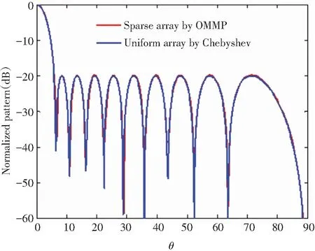
Fig.1 Comparison of the pattern obtained by OMMP with the expected pattern

Fig.2 Element distribution of OMMP synthesizing Chebyshev pattern
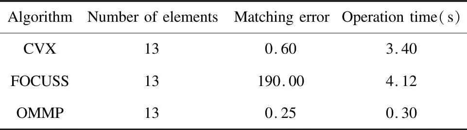
Table 2 Comparison of OMMP and other algorithms in synthesizing Chebyshev pattern
Example2: Taylor pattern synthesis.
Next, it is required to synthesize a thin-line linear array to realize a 29-yuan Taylor pattern with a sidelobe level of -25 dB using as few array elements as possible. Fig.3 and Fig.4 show the results of array synthesis using the proposed method. Table 3 illustrates the comparison between the results obtained by the method proposed in this paper and those in previous literature. The research in Ref. [21] used the CVX method to optimize and successfully combined an 18-element thin cloth array with a matching error ofε=2.43×10⁻⁶. In Ref. [22], the FOCUSS method was adopted and an 18-element array with matching error ofε=6.7×10⁻⁵was successfully synthesized.
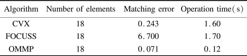
Table 3 Comparison of OMMP and other algorithms for synthesizing Taylor pattern
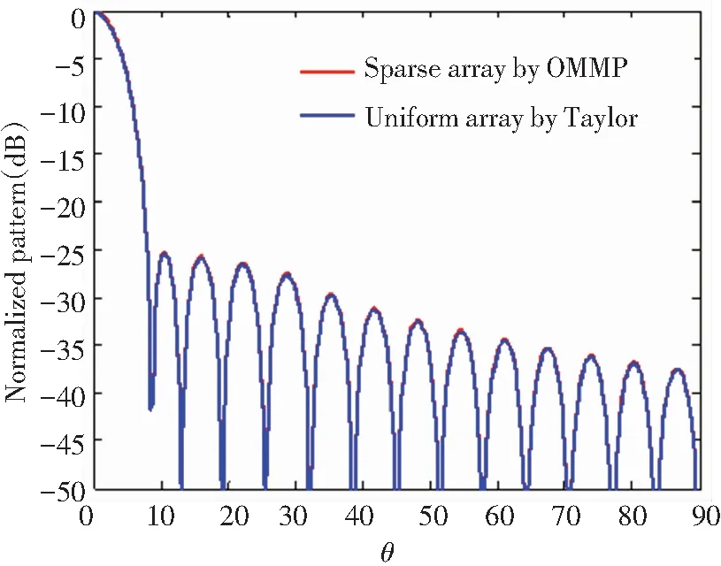
Fig.3 Comparison of the pattern synthesized by OMMP with the expected Taylor pattern

Fig.4 Element distribution of OMMP synthesizing Taylor pattern
By comparison, the OMMP method ultimately gained 18 array elements, but the matching accuracy with the desired pattern was the highest with the least operation time.
Example3: Chebyshev plane array synthesis.
Assume that the desired pattern is produced by an inseparable Chebyshev plane array. The array aperture is 5.5λ×5.5λ, the array element spacing is half wavelength, which is uniformly distributed on the rectangular grid, and the peak sidelobe level is -20 dB. In Ref. [21], CVX algorithm was successfully used to reconstruct the desired pattern with 96 array elements, and the matching error is 3.65×10⁻³. The SEALM method is used in this paper for synthesis and compared with that in Ref. [21]. In the process of turning this comprehensive problem into a sparse signal recovery problem, a completely consistent strategy was adopted. That is, the symmetry of the array was fully considered. Only a virtual uniform array was constructed in the first quadrant, and the sampling point of the desired pattern was taken as 10×20. The reconstruction was then performed by the SEALM method. Simulation results show that the synthetic sparse array finally succeeded in reconstructing the desired pattern with 92 array elements, and the matching error was 8.1 s. Compared with CVX algorithm, the SEALM-based pattern synthesis method could achieve the desired pattern with fewer array elements and better matching accuracy. The combined results are shown in Fig.5 and Fig.6.

(a) Expectation pattern
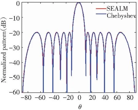
(a)Cutaway view at φ=90°
4 Conclusions
Aiming at the problems in antenna design, the perception matrix was constructed by setting virtual uniform spaced array, and the measurement vector was obtained by low-dimensional sampling of the desired pattern. The problem of pattern synthesis was transformed into the problem of sparse signal recovery. An improved OMP algorithm and an improved EALM algorithm were introduced to recover sparse signals. Finally, the radiation pattern which is very close to the original uniform array could be obtained by saving 20%-30% of the array elements. The paper provides a new method for the miniaturization and economy of array antenna.