Multi-channel DMA Based Design of Voltage Monitoring Using Synchronous Frequency Trace-Sampling Technique
2020-12-18
1.NARI Group Corporation (State Grid Electric Power Research Institute),Nanjing,Jiangsu,210003,China
2.Tianjin Pinggao Intelligent Electric Co.Ltd.,Tianjin,300251,China
3.Nanjing Normal University School of Electrical and Automation Engineering,Nanjing,Jiangsu,210023,China
Keywords:
Voltage monitoring
DMA
Synchronous sampling
Frequency tracing-sampling
MQX RTOS
ABSTRACT
In order to eliminate the influence of frequency change on real-time voltage acquisition,a low-cost solution of voltage monitoring was proposed using the multi-channel DMA synchronous frequency trace-sampling technique.In-chip resources of the designed voltage monitor were fully utilized in hardware design to reduce external devices.The MQX RTOS was used to perform the functional tasks flexibly and efficiently; especially the Ethernet communication applications and USB device connection were realized using its TCP/IP protocol stack and USB driver.In addition,to ensure the safety of electrical records,data statistics and alarm information management were also implemented through the management of the storage in FLASH.The test results show that the voltage monitor designed in this paper has the advantages of accurate measurement,strong resistance to frequency interference and low cost,and can be widely applied in the field of voltage monitoring in distribution networks.
1.Introduction
With the continuous expansion of the power system scale,the nonlinear,shock and asymmetric loads increase day by day in the power grid.Therefore,whether the voltage can be measured accurately is one of the prerequisites to solve the problem of power quality.However,the voltage acquisition is not accurate due to the fluctuation of power network frequency.To solve this problem,it is urgent to develop measurement equipment with high measurement accuracy,low cost and wide application range[1-2].
The voltage monitor designed in this paper can measure,analyze and calculate real-time voltage,current,frequency,harmonic and other parameters.The daily and monthly statistical data and alarm information of the voltage are recorded,and the data are remote transmitted according to the I1 interface network communication specification of the power supply voltage automatic acquisition system,providing timely and accurate data for power quality management and power load dispatching.
2.Hardware Design of the System
The hardware principle diagram of voltage monitor designed in this paper is shown in Figure 1.

Figure 1.The hardware principle block diagram of voltage monitor
The core processor of the voltage monitor is NXP’s MK60FX512VLQ15 based on Cortex-M4 kernel,with a main frequency of 150MHz.It has floating-point operation unit,multi-channel flexible configuration of 32-bit DMA,1MB Embedded Flash and 128KB RAM,2 16-bit SAR ADC modules with PGA,FlexBus extension bus,and several timer modules with different functions.It has a extremely rich communication interface.These powerful on-chip resources and rich communication interfaces provide great convenience for device hardware and software design[3].
This voltage monitor designs 600mAh NI-MH battery as backup power supply.Through two SPI interfaces,NRSEC3000 security encryption chip and SPI-Flash of ST company model M25P32 were extended respectively.Epson’s high precision real-time clock module,RX-8025T,is connected via the IIC interface.The MK60FX512VLQ15 incorporates an internal 10/100Mbps Ethernet MAC layer and provides a common MII/RMII interface.
It should be noted that all the devices of the voltage monitor designed in this paper are industrial-grade type selection,which ensures the reliability of its operation from the basic hardware.
3.The Principle and Implementation of DMA Synchronous Follow - Frequency Sampling
The application of DMA(Direct Memory Access) technology in embedded operating system to deal with AD conversion of multi-channel and large data volume can not only avoid the instability of nested interrupt mechanism,but also improve the efficiency of data conversion and reduce the impact on system task scheduling.MK-60FX512VLQ15 is capable of DMA transfers through independent programmable channels allocated internally by different functional modules[5].
In order to realize synchronous sampling of a phase voltage and current (take Phase A as an example),Ua was connected to ADC0_DP0 pin after PT transformation and analog signal conditioning circuit on the hardware,and Ia was connected to ADC1_DP0 pin after CT transformation and analog signal conditioning circuit.It should be noted that the voltage and current signals of the same phase only need to be connected to different ADC modules,and the channels of ADC modules can be flexibly selected according to the specific hardware configuration.
On the software,the DMA function of the TIMER FTM0 of the MK60FX512VLQ15 processor is configured to enabling state,and the two channels FTM0CH0 and FTM0CH1 of FTM0 are configured as the trigger source for ADC0 and ADC1 to start the AD transition.In this paper,the analog sampling is 64 points per week,and the FTM0 clock source is 75MHz.Therefore,the initial calculation formula of FTM0 is as follows:

The software key statements for the above functions are as follows:

The process of using DMA multi-channel synchronous and frequency sampling technology is shown in Figure 2.

Figure 2.Block diagram of synchronization and frequency sampling based on Multi-channel DMA
It can be seen from Figure 2 that the device’s frequency following sampling is completed by DMA interrupt.In the DMA interrupt service function,the current AC input frequency and the FTM module’s overloaded count value are calculated according to the average value of the phase Angle offset of the three cycles calculated in the main cycle.In this way,the next AD conversion is triggered by FTM based on the new count value,thus realizing the real-time tracking of the sampling frequency to the actual frequency.
4.Software Design of the System
The voltage monitor software designed in this paper is based on MQX embedded operating system[4].
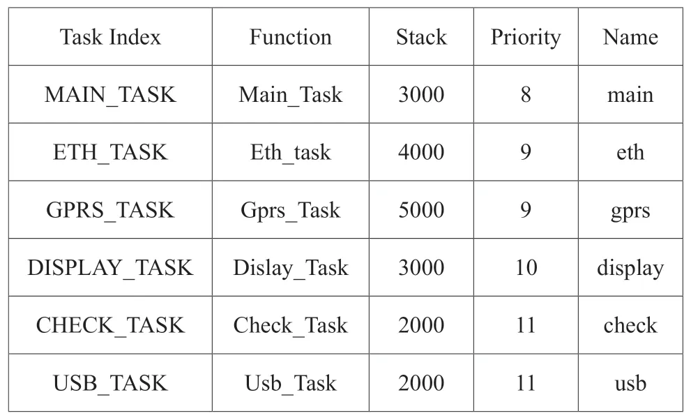
According to the functional requirements of the voltage monitor,the software system of the device is divided into six different tasks.Considering the importance,real-time performance and memory occupancy of each task,the corresponding priority and stack space are allocated.The list of installation system tasks is shown in Table 1.

Table 1.The list of installation system tasks
MAIN_TASK is the main task,mainly completing such functions as power-on initialization and self-detection,program upgrade,event recording,data statistics and storage,etc.This task is self-starting and has the highest priority among the five tasks.
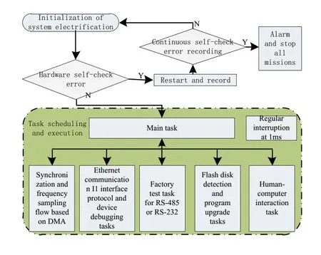
EHT_TASK is Ethernet communication task,which can be configured as debugging interface or I1 standard communication interface according to parameter settings.GPRS_TASK is the GPRS communication task.DISPLAY_TASK is a human-computer interaction task.CHECK_TASK is a factory test task.USB_TASK is an upgrade task for U disk program,mainly completing the functions of U disk detection,file detection and reading,etc.In addition,the software is also equipped with a 1ms timed interrupt,which is responsible for handling functions with high real-time and light load,such as timing,running light,counting and other functions.The overall software framework is shown in Figure 4.

Figure 4.The software principle block diagram of voltage monitor
5.Experimental results and analysis
The developed voltage monitor was tested according to the Standard Q/GQW 1819-2013 Technical Specification for Voltage Monitoring Devices of The State Grid Corporation of China.The test condition is that each input quantity shall be input for 5 minutes,the debugging software shall be set up,and the maximum and minimum values of the measured data of the device shall be recorded within 5 minutes.The test data of frequency conversion are shown in Table 2.

Table 2.The sheet of frequency test data
From the data in Table 2,it can be seen that the tracking algorithm based on DMA interrupt mechanism is very accurate in the estimation of frequency,which lays a foundation for high-precision sampling and calculation of AC volume.The test data table of AC input precision is shown in Table 3.

Table 3.The sheet of AC input precision test data
It can be seen from the data in Table 3 that,at room temperature,the relative error of voltage monitor’s sampling calculation on AC volume is within 1‰,and the frequency variation has little influence on the sampling accuracy,and the sampling accuracy and stability are high.
6.Conclusion
The voltage monitor designed in this paper based on DMA multi-channel synchronous and frequency-following sampling has the advantages of high measurement accuracy,strong anti-frequency interference ability and low cost.The use of MQX operating system,using its own Ethernet and USB resources,not only greatly improve the development efficiency,but also ensure real-time and reliability,can be widely used in the field of distribution network voltage monitoring.
