Application of Aerodynamic Optimization Design and Dynamic Numerical Simulation in UAV Design
2020-12-14SUNKaijunYUYueyangFUYiwei
SUN Kaijun,YU Yueyang,FU Yiwei
CH UAV Technology Co.Ltd,CAAA,Beijing 100074
Abstract:In the past two decades,the world’s unmanned aerial vehicle (UAV) industry has developed rapidly.Various kinds of UAVs have been used in military and civilian fields.Based on the characteristics of UAVs and the development of aerodynamics,this article analyzes the development of aerodynamic optimization design and dynamic numerical simulation technology,then lists engineering applications.Both aerodynamic optimization design and dynamic numerical simulation have greatly shortened the UAV design period and reduced the research and design cost.These two methods gradually replace traditional methods such as wind tunnel test.
Key words:aerodynamic optimization design,dynamic numerical simulation,UAV
1 INTRODUCTION
Unmanned aerial vehicles (UAVs) have been adopted for significant roles in several local wars since 1990s.They have become an important part of the information weapon delivery system,playing a unique role in the field of information support,information warfare,and target prosecution,which has attracted great attention of the military in many countries.At the same time,UAVs have played an increasingly important role in civil rescue and disaster relief,meteorological research,ocean exploration and other fields[1,2].
Unlike manned aircraft,UAV design has the characteristics of short R&D period,low cost,and fast updating iterations.Thus it is impossible to find the best design through a large number of wind tunnel tests in the early stages of the design.However,with the rapid development of high-performance computers,the current UAV aerodynamic shape design is optimized by using computers,and combined with computational fluid dynamics (CFD) for high-precision numerical simulation firstly with repeated iterations to meet the design goals secondly.Finally,wind tunnel tests are carried out for verification.In most cases,some low-cost UAVs have no wind tunnel test at all,and the complete aerodynamic performance of the UAV can be obtained through high-precision numerical simulation using computational fluid dynamics.
Based on the development of aerodynamic optimization design technology and dynamic numerical simulation technology,this paper analyzes the role in the UAV design stage to provide a reference for following UAV design and updates.
2 AERODYNAMIC OPTIMIZATION DESIGN
Aerodynamic optimization design is a discipline that studies how to combine modern computational fluid dynamics and numerical optimization algorithms to find the optimal aerodynamic shape automatically which meets the design requirements.This discipline combines aerodynamics,computer technology,artificial intelligence (AI) and optimization theory and methods.In other words,aerodynamic optimization design means using computers to design the best aerodynamic shape.
Aerodynamic optimization design is usually applied to aircraft design.The Cut-and-Try method currently used relies heavily on the designer’s experience,and often it cannot find the ideal optimal shape.The application of the aerodynamic optimization design can not only reduce the dependence on the designer’s experience,but also help discover new flow mechanisms and explore new aerodynamic layouts.
2.1 Parametric Modeling
Parametric modeling technology is the basis of aircraft aerodynamic shape design.The parameterization of aircraft aerodynamic shape means the method of describing the aerodynamic shape or its changes by establishing a certain number of independent parameter mathematical models according to the characteristics and design requirements of the aerodynamic shape.Shape parameterization is an important part of aerodynamic optimization design research.The accuracy of parametric method has an important impact on the completeness of the design.The parametric method is one of the crucial factors that determine the optimization design efficiency and the final optimization effect.
When designing aircraft,different parametric modeling techniques are used for different components and configurations to meet the design requirements for different refinement levels at different design stages.For example,Hicks-Henne[3],CST[4,5],PARSEC[6]and non-uniform rational B-spline (NURBS) methods could be used for parameterization of two-dimensional sections and parts.For the three-dimensional components and the complex aerodynamic shapes,secondary development CAD (such as CATIA),spline surface,free deformation (FFD)and other parametric modeling methods could be used.
2.2 Multi-objective Genetic Algorithm Based on Surrogate Model
The optimization method based on the surrogate model (shorted as ‘surrogate optimization method’) has become widespread because of its high efficiency and practicality.The surrogate optimization method could replace complex,computational expensive trials or numerical simulations by employing mathematical models involving relatively small amounts of computation.Its main advantage is decreasing the number of calls to the flow field analysis program by establishing an approximate model,which greatly reduces the computation time in the optimization design process.Presently,approximate models including the response surface model,Kriging model,radial basis function model are commonly used.The Kriging surrogate model[7-9]has the strong ability to solve highly nonlinear,multipeak functions,and most aerodynamic optimization problems are inherently highly nonlinear.Thus the Kriging model is a suitable choice.When using the optimization algorithm for optimization,using the Kriging model instead of time-consuming flow field analysis can greatly reduce the time to optimize the design process and improve the efficiency of optimization.
The genetic algorithm not only has the characteristics of global optimization,but also has good robustness,reliability and portability.Therefore,the genetic algorithm has been widely used in engineering optimization.For this reason,the genetic algorithm is employed to optimize and acquire the maximum value of EI[10]and the minimum value of Kriging model.The test sample points are obtained by the Latin hypercube method[11].The optimization design process based on the Kriging surrogate model is shown in Figure 1.
2.3 Application of Aerodynamic Optimization Design on UAV
2.3.1 Aerodynamic layout design of an UAV
Currently,there is an urgent military demand for high-altitude high-velocity UAV.An UAV includes high-altitude reconnaissance and aerial testing platforms.Based on the development trend of high-altitude high-velocity UAVs,the hybrid wing body (HWB) layout is proposed,a hybrid layout that combines a wing-body fusion layout and a conventional layout.

Figure 1 Optimization design flow chart
Before optimizing the aerodynamic shape of the wing,the wing shape needs to be parameterized.Given the wing area and length,the inner wing part is a complex trapezoid wing,and the outer wing part is a swept trapezoid wing.Thus seven variables,the root chord Cr,the length L,the tip chord Ct,the installation angle of the wingΦ,the twist angle of the tipθ,the sweep angleα,and the outer wing part L0,could fully describe three-dimensional wing (Figure 2).
Combining Kriging surrogate optimization method and numerical simulation,an aerodynamic layout that meets the cruise requirements,stall requirements,and high lift-drag-ratio is obtained with repeated iterations (Figure 3 and Figure 4).
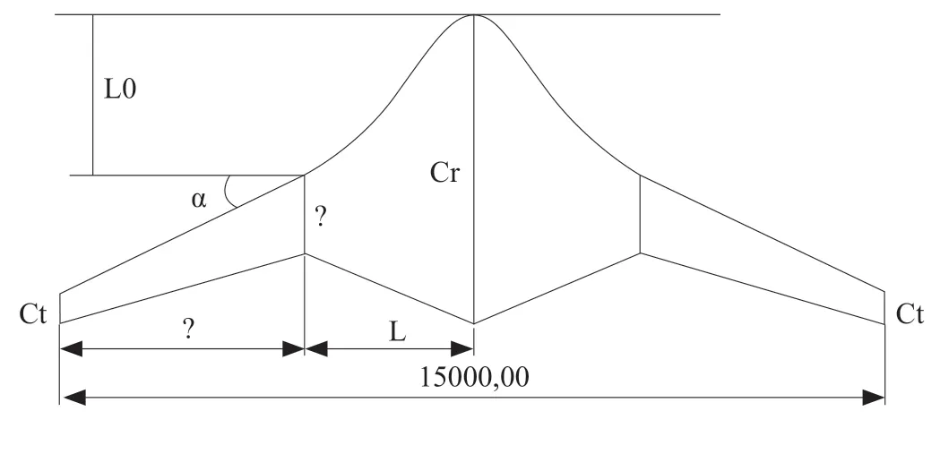
Figure 2 Parameterization of the wing

Figure 3 Optimization design results

Figure 4 UAV lift-drag-ratio Vs angle of attack
2.3.2 Rotor aerodynamic shape design of unmanned tilt-rotor aircraft
The tilt-rotor aircraft has two states:vertical take-off and landing (hovering),and cruising.During the hovering state,the thrust generated from rotor equals to the weight of aircraft.While during the cruising state,the thrust generated from rotor equals to the drag of aircraft.Therefore,the thrust required from rotor for the hovering state is more than ten times that of the cruising state which makes it difficult to design a rotor that can meet the requirements of both states.
The chord length C and the twist angle Beta distribution of the rotor are parameterized by the CTS method.The rotor speed Nc and the total pitch angle Theta of the cruising state are used as design variables adding in the optimization design process.The eighth order of Bernstein polynomial function is shown in Figure 5.

Figure 5 Bernstein polynomial function
After repeated iterative design,the optimal design results of the rotor are obtained (Figure 6):the thrust in hovering state is 264.2 kg,and the efficiency is 78.6%; while the thrust in cruising state is 22.4 kg,and the efficiency is 70.7%,which meets the design requirements.
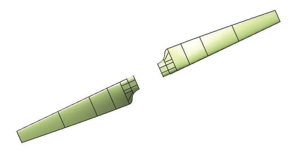
Figure 6 Optimization results for the rotor
After the design phase,the wind tunnel test would be conducted to verify the design results.Figure 7 shows the wind tunnel test model.Figure 8 shows the opened wind tunnel.Figure 9 gives the comparison between the wind tunnel test and the CFD results at a collective pitch angle of 5.6°.Figure 9 indicates that the results of two methods are in good agreement.It demonstrates that the aerodynamic optimization design is reliable.

Figure 7 Wind tunnel test model
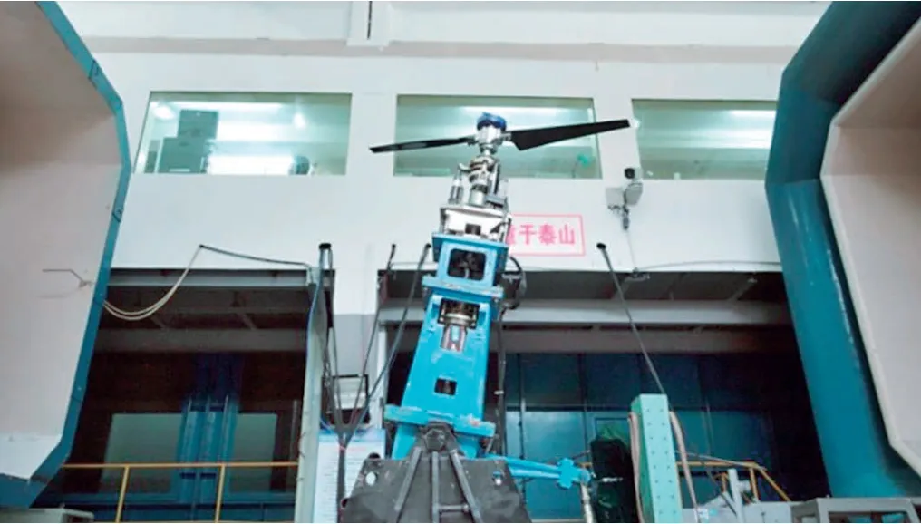
Figure 8 Opened wind tunnel

Figure 9 Wind tunnel test and CFD (collective pitch angle 5.6°,speed 0 m/s)
3 DYNAMIC NUMERICAL SIMULATION
Wind tunnel tests can not fully simulate actual flight conditions in many cases due to the limitation of the equipment.For example,propeller wind tunnel tests need to simulate three similar conditions inchuding Advance ratio,Mach number,and Reynolds number,but most wind tunnels can not meet the requirements.Another reason is the dynamic separation test (to capture trajectory system test,shorten as the CTS).It has a high demand on test environment,equipment and hence the cost.
CFD technology is a numerical method that has developed rapidly in the area of aerodynamic research.It has been well applied in theoretical research and industrial design.However,dynamic numerical simulation technology is one of the difficulties in CFD.Now with the rapid development of high-performance computers,it has gradually replaced some expensive and time-consuming wind tunnel tests,in order to accelerate the design process.
3.1 Embedded Grid Technology
Embedded grid technology is the foundation of CFD.Embedded grid has been widely used and has developed rapidly since proposed in 1985 by Benek,J.A.[12].It solves the difficult problem of the poor quality of structured grids in simulating complex shapes or complex flows.Researchers have applied embedded grid technology to the numerical simulation for the flow around complex shapes such as two-dimensional airfoils,three-dimensional wings with ailerons and flaps,and entire aircraft,which greatly promoted the development of the embedded grid technology application.When dealing with objects with relative motion,motion embedded grid technology[13,14]has been proposed,which enables the wide application of embedded grid in simulating complex and unsteady flows.For example,the oscillating motion of a two-dimensional airfoil,three-dimensional missile launch and dynamic numerical simulation of a rotor.
3.2 Application of Dynamic Numerical Simulation on An UAV
3.2.1 Aerodynamic interference of rotor-wing/fuselage on unmanned tilt-rotor aircraft
Currently,an important factor affecting the flight performance of tilt-rotor aircraft is the strong aerodynamic interference between the rotors and the wing in the hovering state.In the hovering state,the rotor tip vortex shed from the tip of the rotor not only affects rotor blades,but also the downwash induced asit hits the wing vertically,which generates a complex blocked three-dimensional effect flow field on the upper surface of the wing.This downwash loads on the wing have an negative impact on the aerodynamic performance of the tilt-rotor aircraft.Therefore,research on aerodynamic interference of tilting rotor-wing/fuselage is significant to reduce interference.It is difficult to simulate this problem in wind tunnel tests,accordingly dynamic numerical simulation is important in this research.

Figure 10 Tilt-rotor unmanned aircraft

Figure 11 Streamlines of fountain flow phenomenon
Figure 10 shows an unmanned tilt-rotor aircraft,and Figure 11 shows a dynamic numerical simulation of the rotor-wing/fuselage interference flow field in the hovering state.It can be clearly seen,the influence of the wing and fuselage on the flow field:an obvious fountain effect appeared above the fuselage.As the upward air flow circulates up due to the rotor it exceeds a certain height,due to adsorption of the rotor disc,then it flows down through the rotor disc plane,thereby forming a circular air flow.
Table 1 shows the comparison of the average thrust of a single rotor and a rotor/aircraft in the calculation period.It shows that the rotor components for the entire aircraft slightly increase the thrust force of the rotor by 3% compared to those of a single rotor,due to the combination of the ground effect of the wing and the “fountain effect” of the fuselage.In addition,due to downwash,the wing generates a negative lift,located in the fixed section of the wing,equivalent to 16% of the thrust of the single rotor.While the outer wing section has a smaller loss due to rotation from the rotor.At the same time,the fuselage produces a negative lift of 3.6% due to downwash.The downwash effect on the vertical tail and horizontal tail is ignored.In summary,the total thrust of the entire aircraft is 83.4% of that of a single rotor.It can be deduced that the wing and fuselage have a significant negative impact on the rotor performance.

Table 1 Comparisons of thrust between rotor and entire aircraft
Figure 12 shows the velocity map of center of rotation of the rotor in the Y axis.Combined with Figure 11,it indicates that vortices appear above the fuselage and below the wing due to the shielding effect of the wing/fuselage.
Figure 13 is the vorticity distribution between rotor and wing/fuselage.It describes the spatial position and movement of the rotor tip vortex.The root of the wing and the top of the fuselage have vortex induced by the fountain effect.

Figure 12 Velocity contour at the center of rotation along Y axis

Figure 13 Vorticity distribution between rotor and wing/fuselage
3.2.2 Dynamic separation of UAV airborne dropsonde
At present,the research on dynamic separation mainly focuses on the separation safety regarding airborne missiles for manned aircraft.There is little research on the separation safety for light and unpowered devices,especially when using low-speed propellers in a pusher configuration.This problem is difficult to solve through CTS wind tunnel tests,but dynamic numerical simulation can solve this problem well.
This section takes a mid-to-high altitude long endurance UAV as an example to study the dynamic separation process of an airborne dropsonde in high crosswind through dynamic numerical simulation.Figure 14 is a diagram of the spatial position change with time after the dropsonde separates taking the propeller slipstream in to consideration.Figure 15 (a) is the UAV vortex distribution,and Figure 15 (b) is the streamline near the UAV propeller.
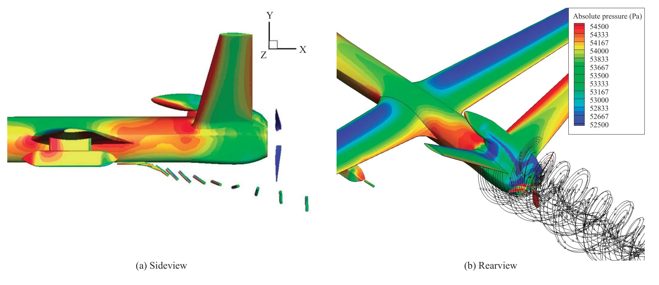
Figure 14 Radiosonde drop

Figure 15 Vortex and streamline
4 CONCLUSION
With the rapid development of high-performance computers,it has become a reality to combine optimization algorithms and CFD methods for UAV aerodynamic layout optimization design,which greatly accelerates project progress and reduces the need for experienced designers and significantly improves the aerodynamic performance of the UAV.Therefore,advanced aerodynamic optimization design methods not only are used for theoretical research,but also in engineering applications.
At the same time,with the rapid development of computer performance and multi-core parallel technology,high-precision numerical simulation has been greatly developed,and there is a trend for this technology to gradually replace wind tunnel tests.Limited by the wind tunnel test in the past,dynamic numerical simulation has been developed as an important method to solve engineering problems.
杂志排行

Aerospace China的其它文章
- The LM-11 Carrier Rocket is Launching from a Ship
- Trajectory Design of Launch Vehicle with the Argument of Perigee Constraint for Highly Eccentric Orbit Mission
- LM-2D Carrier Rocket Has Made a Record of 50 Launch Successes in a Row
- Acquisition and Tracking Technology for Space Laser Communication
- Numerical Simulation of Rolling Stability of Flight Vehicle
- Prospect of Near-Space Exploration and Scientific Experiment Carrier Platform Demand