Battery package design optimization for small electric aircraft
2020-12-09MingkiWANGShugungZHANGJohnnesDIEPOLDERFlorinHOLZAPFEL
Mingki WANG, Shugung ZHANG,*, Johnnes DIEPOLDER,Florin HOLZAPFEL
a Institute of Aircraft Airworthiness Engineering, School of Transportation Science and Engineering, Beihang University,Beijing 100083, China
b Institute of Flight System Dynamics, Department of Mechanical Engineering, Technical University of Munich, Garching D-85748,Germany
KEYWORDS
Abstract The increasing gross weight of electric Unmanned Aerial Vehicle (UAV) poses a challenge in practical applications.The range and endurance of the electric UAV are limited by the fixed mass of the battery package. In this work, a design optimization method for the battery package topology of small electric UAV is proposed to enhance the performance. To improve the accuracy of the method,the dynamic battery model and simplified electric component models are presented.These models are utilized by the trajectory optimization method, which takes the dynamic characteristic into consideration to calculate the aircraft performance.The direct optimal control method is used for solving the trajectory optimization problem, and this method is tested on a small blended-wing-body electric aircraft. The test result shows that the range and energy-consumption are mainly influenced by the parallel topology of the battery package,while the flight time in climb phase is more sensitive to the series topology. It is deduced that the range- and energy-optimal design points can be considered concurrently in design optimization.The work proves the feasibility of integrating the trajectory optimization and battery package design.
1. Introduction
In the past decade, the development of the Unmanned Aerial Vehicle (UAV) has benefited agriculture, delivery, and resource surveying. The battery is a common energy source applied to UAV.1,2In that case,this kind of aircraft can be further categorized as electric UAV.In addition to the advantages of lower noise level and greenhouse-gas emission, the electric UAV is also more likely to take advantage of new configurations (e.g., boundary layer ingestion and distributed propulsion) to achieve short or vertical takeoff and landing.3,4However,the lower energy density and power density of the battery will lead to a higher gross weight for the same performance requirement as the conventional aircraft, which limits the usage of the electric UAV.5,6In this context, it is necessary to conduct design optimization based on the current battery technology.
Component modelling and performance calculation are two main problems in the design optimization of electric UAV.One of the challenges in electric UAV modelling is to represent the features of the electric propulsion system. Efforts have been made to incorporate the dynamic battery model in component modelling. For instance, the Peukert effect of the battery is included in range and endurance estimation to describe the current influence on the available capacity.7Furthermore,the battery voltage drop is reflected to improve the aircraft performance calculation accuracy.8–10
Besides the estimation method based on historical data,the trajectory optimization method is employed to calculate the electric aircraft performance as well. Numerical methods are commonly used to solve large-scale trajectory optimization problems.11These numerical methods can be categorized into direct and indirect methods.
In direct method, the optimal control problem is first discretized and then solved numerically using iterative parameter optimization schemes.11Typical direct methods include single shooting,multiple shooting,and collocation methods.The single shooting method yields a small but strongly coupled problem. Despite its simplicity, one drawback of the method is the usually high sensitivity of the solution with respect to the initial condition. As a modification of the single shooting method, multiple shooting method partitions the time interval into several segments. This decouples the problem and thus improves the stability as well as accuracy of the method. The shooting methods mentioned above have successfully been applied in rocket launch and orbit transfer problems.Collocation methods are different from the shooting method as both the states and the controls are fully discretized and highly stable implicit Runge-Kutta methods can be used.The full discretization increases the dimension of the nonlinear programming problem, but the problem also becomes highly decoupled, leading to a large scale but sparse parameter optimization problem.With the development of the hardware and the corresponding software tools, the collocation method provides programmatical access to solving the trajectory optimization problem.
In case of indirect methods, the necessary conditions of optimality are derived based on Pontryagin’s maximum principle. This leads to a two-point boundary value problem which can be solved numerically or analytically.These indirect methods yield highly accurate solutions and in particular reveal the underlying structure of the optimal control problem.The indirect methods require the analytical derivation of the necessary conditions,the priori knowledge about the switching structure of the problem, and the generation of good initial guesses for the numerical solution.These drawbacks often make it impractical to implement the indirect methods for real world applications.
The energy optimal related problem is of much concern when the trajectory optimization is applied to the electric UAV. The challenge is to build up a simulation model which is able to reflect the internal relationship of the propulsion system and to derive the additional constraints accordingly. A trajectory optimization method proposed by Falck et al.12explores the thermal constraints of the electric propulsion system. The work is enlightening for building detailed electric propulsion model and thermal equilibrium equations. The derived optimal trajectory is thus more realistic, but the combination of the trajectory optimization and the design optimization still remains to be explored. Guilherme et al.13presents the analytical and numerical solutions to the energyoptimal trajectory of the electric aircraft. However, the calculation of the required power in the work does not consider the performance limit of the battery package and the motor.Therefore, the path constraints of the electric propulsion system should be included in the optimization.
In this paper, an integrated approach combining trajectory optimization and battery package topology design optimization is proposed to improve the performance of small electric aircraft.To this end,a simulation model of the electric aircraft with detailed propulsion system is built.The performance constraints of the electric subsystem are discussed on the basis of the model. With the derived constraints, the performance optimization problem is solved with a steady-state assumption and the solution is compared to the numerical optimization result.The design optimization method for the battery package is ultimately deduced from the previous calculation and analysis.
2. Electric aircraft simulation model
2.1. Aircraft point mass model
The point mass model is employed in the trajectory optimization problem14

where V is aircraft airspeed, γ is the flight path angle, x is the flight distance,h is the altitude,φ is the engine mounting angle,α is the angle of attack, T is the thrust, D is the aerodynamic drag,L is the lift,m is the gross mass,and g is the gravitational acceleration.
2.2. Architecture and principle of electric propulsion system
In this work, a generic electric propulsion system model is utilized (see architecture in Fig.19,10,15) to improve the calculation accuracy. The common approach calculates the power of the electric aircraft by taking the product of the airspeed and the required thrust, which omits the internal mechanism of the propulsion system. Conversely, the proposed model comprising powertrain and drivetrain enables the propagation of the shaft power. The constraints of the components can thus be calculated in the design. In this section, the principles of the powertrain and drivetrain are explained. A static propulsion system model is then derived with reasonable assumptions.

Fig.1 Energy and information flow of a generic electric propulsion system.
2.2.1. Powertrain
The powertrain supplies the generated electric energy from the battery package to the drivetrain.The battery package consists of battery cells in series or in parallel.12The battery cell works as follows: The output voltage is determined by the working current and the remaining capacity, and the discharging process is influenced by the ambient temperature. Fig.2 shows the discharging curve of Panasonic NCR-18650 lithium ion battery at 25°C.16As can be seen from the figure,the available voltage UBof the battery cell varies significantly as the battery consumed capacity QBincreases. The discharging process is therefore divided into exponential zone, nominal zone, and fast-discharging zone to reflect this dynamic feature.17
Currently, there are a variety of models describing the dynamic characteristic of the battery, e.g., Equivalent Circuit Model (ECM),17–19electrochemical model,20and intelligent mathematical model.21With the high fidelity and complexity,the electrochemical model is mainly utilized in the battery design and manufacturing. The mathematical model based on neutral network is suitable for modelling from the experiment data,but requires a large amount of data to train the network, which increases the calculation cost. With lower complexity and acceptable accuracy,ECM is widely employed in research. Thevenin model is one of the ECMs which represents the dynamic feature of the battery by adding a parallelconnected resistance and capacitor. The polarization voltage is considered as a state and integrated over time so that the variation of the output voltage is incorporated. Thevenin battery model is also modified to consider the battery parameter change regarding the state of charge and the environment condition.
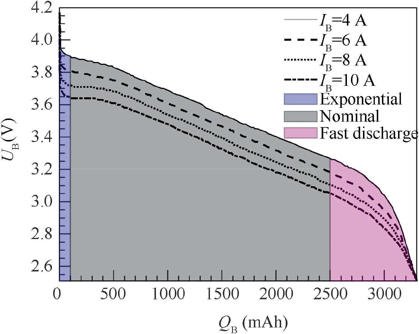
Fig.2 Typical discharging curve of lithium ion battery.15.
The battery model used in this work (Fig.3) is developed from the equivalent circuit theory. Compared to Thevenin model, the employed model is not required to calculate the polarization voltage by integral. The calculation cost of the trajectory optimization is thus reduced. Additionally, the parameters of the model can be acquired from the discharging curve or the data provided by the manufacturer without additional experiment. Moreover, this model has an analytical form instead of interpolation from lookup tables,which avoids the finite difference approximation in the optimization and improves the accuracy of the calculation.
Based on the classical equivalent circuit model,the dynamic model reflects the degradation of the battery output voltage by adding the polarization effect and the exponential voltage.The discharge voltage is17
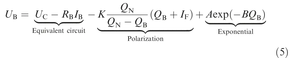
where UBis the battery output voltage, QBis the consumed capacity, IBis the output current, UCis the battery constant voltage, RBis the internal resistance, IFis the filtered current,QNis the nominal capacity, K is the polarization resistance,A is the exponential zone voltage amplitude, and B is the exponential zone time constant inverse. Oliver and Louis17derived the equations to determine the coefficients K, A and B17
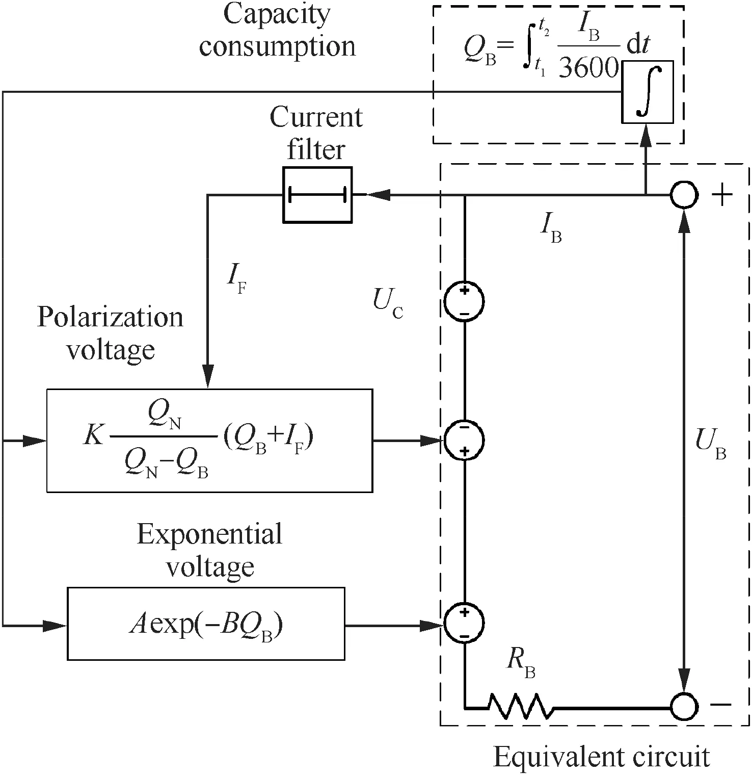
Fig.3 Schematic diagram of dynamic battery model.

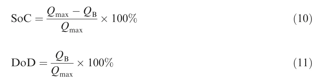
where UFis the battery fully charged voltage,UNis the battery nominal output voltage (usually given by the manufacturer datasheet), Qmaxis the battery maximum capacity, and QEis the exponential zone capacity.
The capacity consumption value (in Ah) in Eq. (5) can be derived as

Unlike its conventional counterpart,the electric aircraft has no fuel consumption. Therefore, State of Charge (SoC) and Depth of Discharge (DoD) are employed to measure the energy consumption
Battery package topology influences the performance and the operational safety.Two types of battery package topology,series–parallel in Fig.4(a) and parallel-series in Fig.4(b), are considered in this work.22When we omit the failure case, the two configurations have no difference in terms of performance.
According to the principles of electric circuits, the output voltage of the battery package UBPis the product of the battery cell output voltage UBand the number of battery cells in series

and the output current of the package IBPis the product of the battery cell output current IBand the number of battery cells in parallel NP

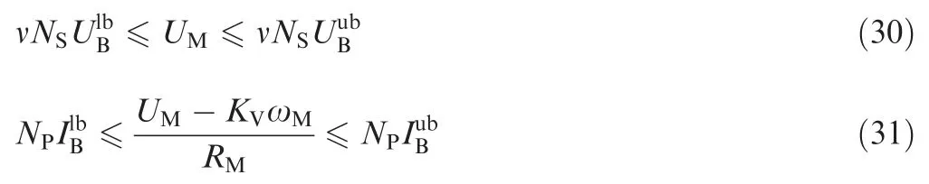
As shown in Fig.2, the output battery voltage and current are coupled and hence the requirement of the current and the voltage from the drivetrain might not be fulfilled simultaneously. In some design cases, it is necessary to use power converter to transform the battery output voltage to the value required by other components.15It is assumed that in this work the weight of the power converter remains the same.
2.2.2. Drivetrain
The drivetrain subsystem (Fig.5) of the small electric aircraft generally contains BrushLess Direct-Current (BLDC) motor,Electric Speed Controller (ESC), thrust unit (e.g., propeller,ducted-fan), and an optional gearbox. The ESC is simplified as a Proportional-Integral (PI) controller with the gain of KPand KI. This controller tunes the input voltage of the motor according to the error ωE, which is the difference between the command value ωCand the actual value ωM. The drivetrain transforms electric energy into mechanical energy and provides thrust for the aircraft.
A simplified diagram of the ESC is given in Fig.6. In the signal processing part, the processor generates a signal wave according to the error between the measured and the desired rotational speed. The signal is then taken by the Field-Effect Transistor (FET), which can switch on and off at a high frequency to modify the output voltage.Consequently,duty cycle signal ν from the ESC tunes the output voltage to make the motor follow the desired rotational speed.
The BLDC motor takes the product of the duty cycle and the available voltage UBPof the battery package as the input voltage UM, which tunes the rotational speed to follow the command value

where the duty cycle ν is between 0 and 1.
The BLDC motor is usually used in the electric propulsion system to generate the driving torque.It is composed of stator,rotator, and Hall sensor. A simplified diagram of BLDC motor is presented in Fig.7.
The back-electromotive force (back EMF) induced by the rotation of the motor resists the change in the current. Part of the voltage into the BLDC motor compensates for the back EMF; the other part generates the current to drive the load.The equivalent circuit part in Fig.7 can be expressed as
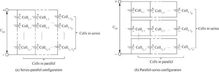
Fig.4 Battery package configuration.21.

Fig.5 Architecture of electric drivetrain.
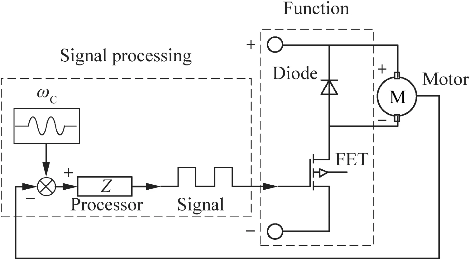
Fig.6 Simplified diagram of electronic speed controller.

Fig.7 Simplified diagram of BLDC motor.

where KVis the motor back EMF constant, ωMis the actual rotational speed, IMis the working current, and RMis the motor internal resistance. The direction of the magnetic field generated by the stator coil changes periodically to drive the rotator to rotate. The consequent torque

drives the load,23where QMis the motor output torque, KTis the motor torque constant,and The aircraft flight status determines the required is the motor damping coefficient.
The propeller and the ducted fan(here unified as rotor)are commonly-used in small electric aircraft for thrust.Compared to the propeller, the ducted fan is enclosed by an annular airfoil (a shroud or a duct) to gain a higher thrust and a lower energy consumption. The modelling methods of the rotor include blade element theory and momentum theory.24–26These methods usually yield equations based on coefficients to calculate the rotor thrust and torque
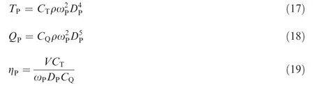
where TPis the thrust,CTis the thrust coefficient,QPis the torque,CQis the torque coefficient,ηPis the efficiency,ρ is the air density, ωPis the rotor rotational speed, and DPis the rotor diameter.The thrust and torque coefficients are usually a function of propeller geometry, Reynolds number Re, blade-tip Mach number Ma,and the advanced ratio λ.In the simulation model, the coefficient data is acquired from the lookup table.

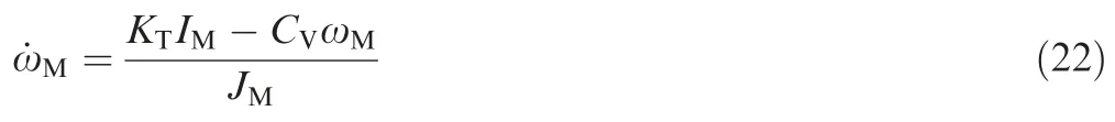
With the driving torque from Eq. (16) and the load torque from Eq. (18), the angular acceleration of the motor is expressed as

where JMand JPare the motor and rotor moment of inertia,respectively. This dynamic drivetrain model is utilized in the parameter estimation method to obtain the motor data. The motor is tested without the external load in the estimation experiment,so the required torque and the inertia of the external load in Eq.(21)are omitted.Substituting Eq.(16)into the simplified Eq. (21) yields
Furthermore, the motor current IMis solved by Eq. (15)and substituted into Eq. (22)

The first-order model from the input voltage UMto the motor rotational speed ωMis thus derived as

where KMis the transfer function gain, and τ is the time constant.
2.2.3. Static electric system model
The static model of the electric propulsion system is proposed in this work for the trajectory optimization of electric aircraft.The basic assumptions are: (A) the dynamic tuning process of the motor rotational speed is ignored;(B)the motor rotational speed is hence the same as the command value;(C)the angular acceleration of the motor is zero; (D) the rotational speed of the motor matches that of the thrust unit so that there is no gearbox.
3. Steady-state solutions
With the electric aircraft model incorporating detailed propulsion system in Section 2, a steady-state solution to the rangemaximum problem is derived in this section. The solution is compared with the numerical optimization results in Section 5 for verification.

Fig.8 shows the chain of the energy transfer and conversion in the electric propulsion system, through which the battery package parameters implicitly influence the flight performance.The total input power into the aircraft is the battery package power PBP excluding the energy loss ΔPBP. The motor generates the mechanical power PM with this input power, which is transferred to supply the propeller power PP and thus the aircraft power PA. Note that the efficiencies of the components (ηBP for battery package, ηM for motor, and ηP for propeller) are included in the energy chain. Instead of only using the power required by the aircraft, which takes the product of the thrust and the velocity, the internal operation mechanism of the electric components is considered in this work to reflect the battery package influence.The initial power requirement stems from the required thrust. Given that the aircraft is in steady level flight with relatively small α and γ, Eq. (1) and Eq. (2) can be simplified as
where CD0is the zero-lift drag coefficient,k is the Oswald efficiency factor,and S is the aircraft reference area.The mechanical power PAof the level flight is
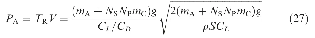
where mAis the airframe(except for the battery package)mass,and mCis the battery cell mass.The required thrust TRis produced by the thrust unit.In the case that the battery package is able to provide the necessary voltage and current for the motor, the required rotational speed can be derived from Eq.(19)
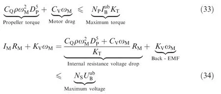
To drive the thrust unit, the shaft power is generated from the BLDC motor. Consequently, the required torque should fulfill the following equation:

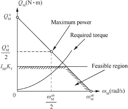
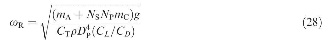
Fig.9 Feasible region of motor operation points.
However,the required torque is not necessarily satisfied by the motor because of the battery package capacity limits. The input voltage and current of the BLDC motor are saturated by the battery package parameters
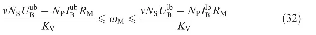
Hence, the rotational speed of the propeller is saturated by the maximum torque that the motor can generate;the required voltage is saturated directly by the maximum available package voltage
The required rotational speed of Eq. (28) is reformulated regarding the saturation case
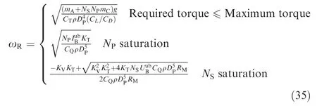
Furthermore, the output thrust is proportional to the square of the rotational speed according to Eq.(17).The available thrust of the aircraft is influenced by battery package parameters via the effect on the drivetrain performance.
To summarize, the drivetrain works as the medium in the interaction of the powertrain status with the aircraft performance and vice versa. The coupling relationships are:
(1) The battery package parameters (the number of batteries in series and in parallel) determine the range of the output voltage and current.
(2) The total number of the battery cells influences the gross mass of the aircraft and thus the aircraft performance.
(3) The aircraft flight status determines the required output voltage, current, and the capacity consumption of the battery package, which in turn influences the available voltage and current.
(4) The increase in the battery cells in series or in parallel does not necessarily benefit the performance because the battery package takes up a significant part of the gross mass of the electric aircraft.
Therefore,there should be optimal battery package parameters for given configuration and flight task to optimize the electric aircraft performance. In this work, three types of battery package design optimization problem are particularly investigated. The corresponding optimization objectives are:
Maximize the flight distance with the available capacity in steady level flight
Minimize the battery capacity consumption for the given flight distance in steady level flight

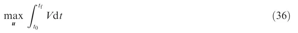
Minimize the flight time and the energy consumption for the given altitude change in climb
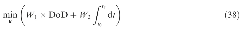
where t0is the initial time, tfis the final time, and W1and W2are the weighting coefficients. The energy-optimal flight task proposed by Eq. (36) incorporates flight time as part of the cost function for feasible solutions.
The range optimization problem is to maximize the flight distance for a given capacity consumption. To simplify, the average value of the aircraft state is taken to calculate the performance. The flight distance x is approximated by
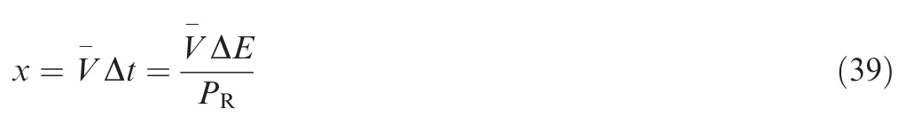
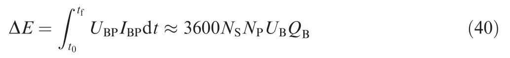
Substituting Eqs. (23) and (24) into Eq. (39) yields


Solving the simultaneous equations formed by the solution above and Eq. (24) yields the optimal lift coefficient

The numerator of Eq. (41) represents the influence of the electric system.The output voltage of the battery cell UBneeds to be maximized to extend the flight distance. Therefore, the electric system should operate at the possible lower bound of the output current according to Eq. (5).
The flight distance response surface regarding the battery package parameters is given in Fig.10(a). The flight distance is not monotonic regarding the battery package topology because both the gross mass and the available energy increase when battery cells are added.There are infeasible design points when the battery package output power is less than that of the motor,as can be seen from Fig.10(b).The optimal parameters lie on the boundary where the series battery cell supplies the minimum power required by the motor.
However, the analytical solution to the range optimization problem includes neither the effect of different battery capacities on the battery available voltage nor the constraints from the battery output power and motor operation range. Therefore,a more accurate methodology should be used to calculate the performance.
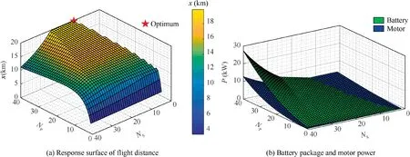
Fig.10 Analytical solutions.
4. Optimal control and optimization method


entering Eqs.(12)and(13)are selected as optimization parameters. These parameters are relaxed to be continuous variables for solving the optimal control problem and are finally rounded to be positive integer values.
In this work, the trajectory optimization problem is discretized using a trapezoidal collocation method to transform the system dynamics, constraints and objective function to a NonLinear Programming (NLP) problem.27–29This NLP problem is then solved by the interior point optimizer IPOpt.30
A blended-wing-body electric aircraft model is used in the numerical example. The aircraft is driven by six ducted fans,as illustrated in Fig.11.
In addition, Table 1 summarizes basic structural and geometrical parameters.
The lift and drag coefficients of this aircraft are modeled according to

where CLαis the lift coefficient slope, and CL0is the lift coefficient at zero angle of attack.
The battery cell data provided in Table 2 is taken from the manufacturer’s manual.16Moreover, the parameters for the BLDC motor model presented in Section 2.2 are determined by a parameter estimation method.31,32
The following path constraints for the optimization are derived from the aircraft performance and safety requirements

The initial boundary conditions corresponding to a steady level flight, and the final boundary conditions are presented in Table 3, where Δh is the altitude change of the flight.
The flight tasks (1)–(3) according to Eqs. (36)–(38) are:
(1) Maximize the flight distance with a free final time and 10% of the available capacity (Δh=0)
(2) Minimize the capacity consumption with a fixed flight distance and final SoC no less than 20% (Δh=0)
(3) Minimizethecombinedobjectivefunction(W1=1,W2=10-4) of DoD and flight time with Δh=500 m
Note that, the initial SoC is less than 100% and the final SoC is larger than 0 for climb and descent.

Fig.11 Configuration of electric aircraft.
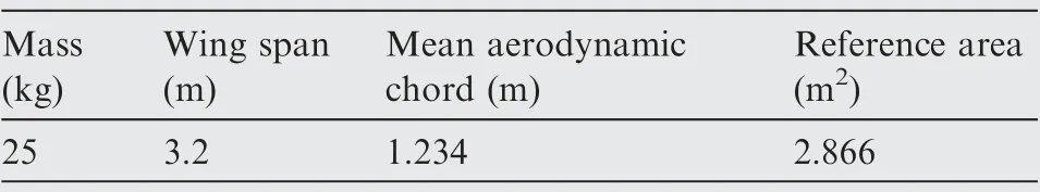
Table 1 Basic parameters of electric aircraft.
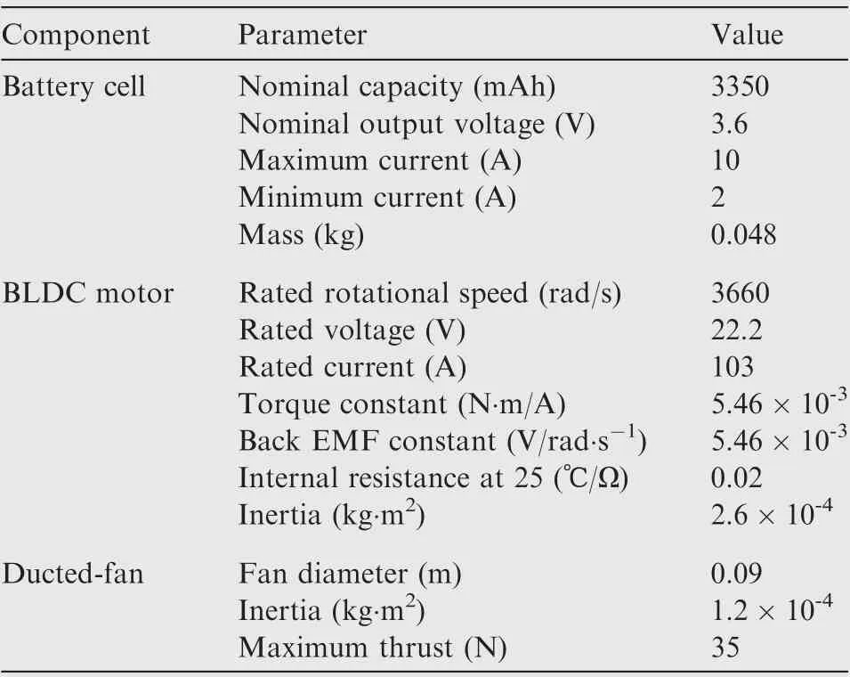
Table 2 Parameters of electric propulsion system.15,30.

Table 3 Boundary conditions of trajectory optimization problem.
5. Results and analysis
5.1. Optimal flight trajectory
The optimization states corresponding to flight task (1) with different battery package parameters and initial capacities are presented in Fig.12.Note that the angle of attack in steady level flight is around the optimal value of the lift coefficient obtained from Eq. (44). In addition, the required power and current are kept at the respective lower bounds in order to maximize the range given a specific capacity.
The numerical result of the flight task (1) also matches the steady-state solution in Section 3.As can be seen in Fig.12(a),the range decreases when the battery package output voltage UBPis higher than the motor required voltage UM. This can be explained by Fig.10(b)where the maximum flight distance is achieved when the power supply of the battery package is at the lower bound.
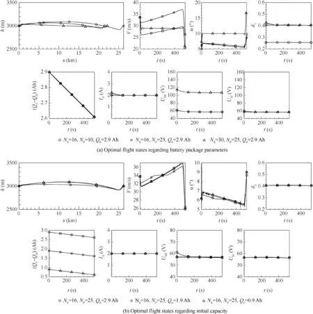
Fig.12 Aircraft states of optimal flight trajectory.
5.2. Performance sensitivity analysis
5.2.1. Range sensitivity
The response surfaces in Fig.13 show that the range of the given aircraft is more sensitive to the number of parallel cells NP.According to the analytical solution in Eq.(41),the motor operates at a low current to extend the flight distance. An increased number of parallel battery cells thus allows for a lower battery cell current to maintain the optimal flight state corresponding to Eq.(44).The number of battery cells in series determines the battery package output voltage. In the flight distance optimization, the parameter NShas no contribution to the performance once the required thrust reaches the optimal value.
For a fixed number of battery cells in parallel, the optimal design points are found on the boundary marked by the red ellipse in Fig.13.This can be explained by the analytical solution illustrated in Fig.10(b).The range-optimal design points are achieved when the extra power of the battery package regarding the required power of the motor is relatively low on the boundary. Furthermore, the benefit of the increased parallel battery cells on this boundary becomes less significant for a higher NPvalue because the velocity is around the optimal value but the increasing gross mass decreases the performance.

Fig.13 Response surface of flight distance regarding battery parameters.
The optimal design point remains the same when we change the initial capacity Q0of the battery (comparison between Figs. 13 (a) and (b)). This is because, for the testbed, the output voltage of the battery package is still able to support the flight despite the voltage drop described by Eq. (5). Thus, a redundancy coefficient in the series cell number should be considered so that the maximum output voltage is able to cover the optimal operation voltage of the BLDC motor.
5.2.2. Energy-consumption sensitivity
The remaining capacity response surface in Fig.14 (a) shares similar geometric features with that in Fig.13. In the range optimization problem, the optimal flight path is also solved to minimize the energy consumption rate according to Eq.(41) and the corresponding analysis.
The energy-optimal design point of climb in Fig.14 (b)takes lower values for NSand NP. This can be explained by comparing the energy consumption in cruise

with the energy consumption in climb

It can be seen that the energy consumption ΔEclis directly influenced by the gross mass. The results in Fig.14 also indicate that a tradeoff of the energy-optimal design point is required for different flight tasks.
5.2.3. Flight-time sensitivity
The flight time in Fig.15 is more sensitive to the series battery cell number in climb.This can be interpreted by the climb rate

where the higher rotational speed directly increases the available thrust, which benefits the climb rate. According to Eq.(15), the rotational speed of the motor is limited by the total input voltage, which is determined by NS. A larger value for NPallows for a lower average current of the battery cells which increases the available voltage of the battery package according to Eq. (5). The consequent higher rotational speed due to an increased value for NPleads to a shorter flight time in climb until the optimum is reached. When the current drops to the lower limit, a higher number of parallel cells only results in a gross mass rise, thus increasing the flight time in climb.
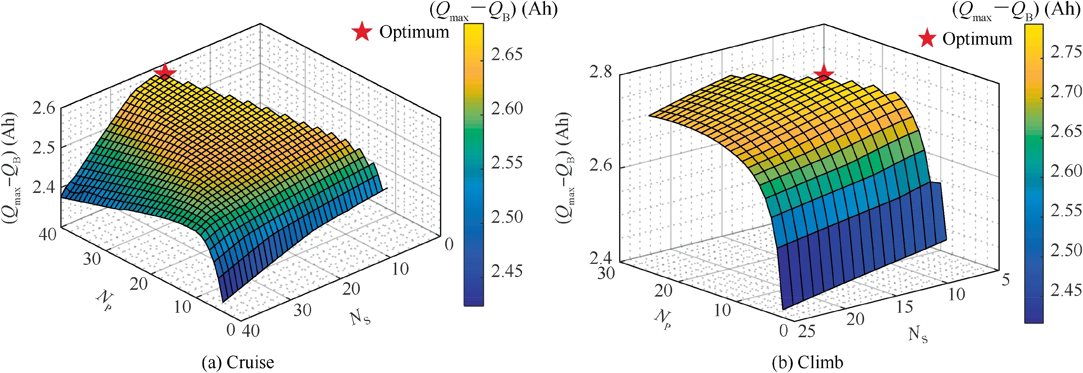
Fig.14 Response surface of remaining capacity.
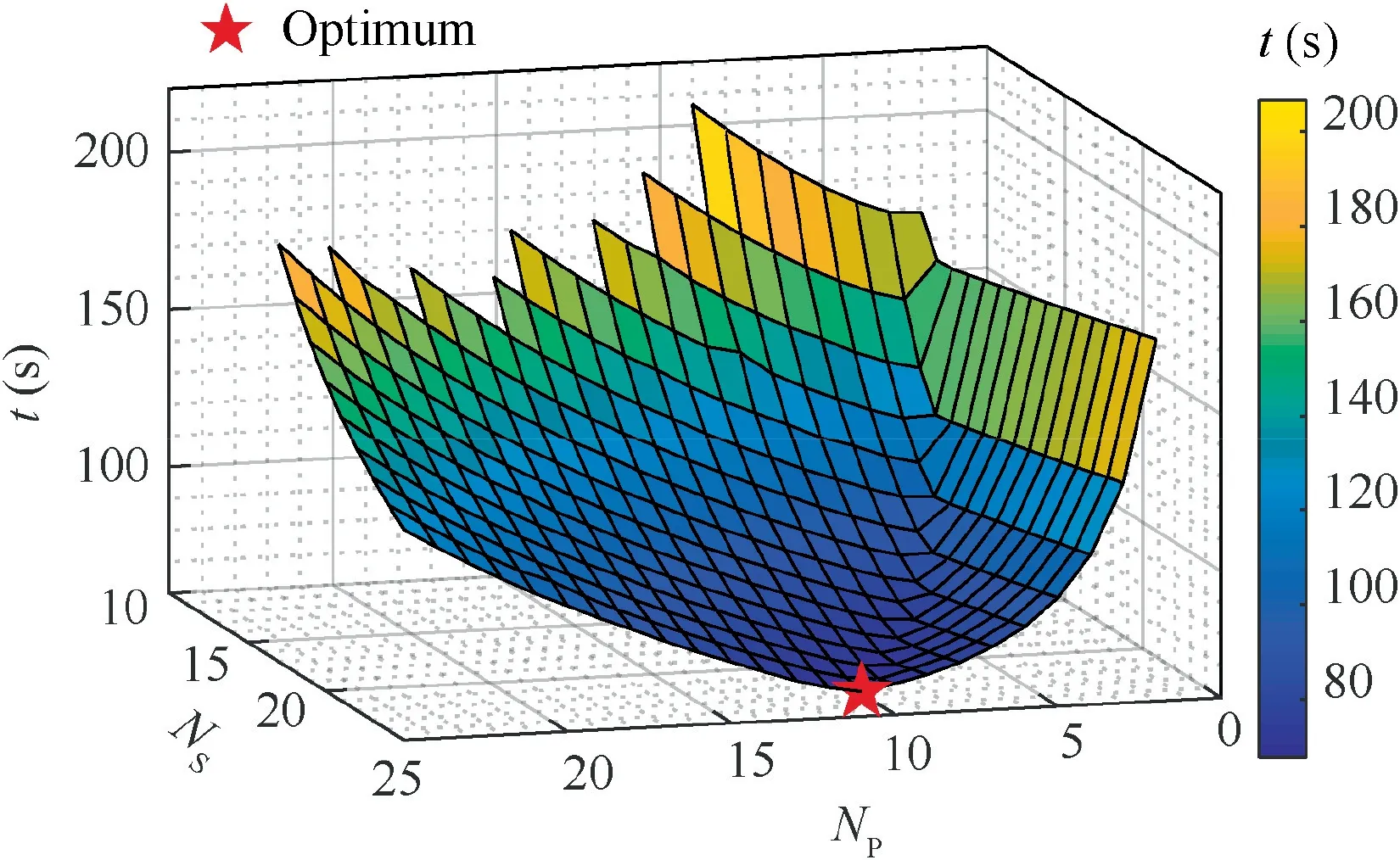
Fig.15 Response surface of flight time in climb.
5.3. Derived battery package design method
To summarize, this work provides an integrated approach to the simultaneous optimization of the battery package topology and the trajectory. For the given flight task and the performance objective,the approach incorporating the dynamic battery model and static component model yields an optimal flight trajectory and the corresponding battery package parameters.The design process illustrated in Fig.16 is divided into three parts,namely the determination of the optimal flight state,the propulsion system design,and the performance calculation.In the first part,the optimal lift coefficient CL0for the given flight task is calculated according to Eqs. (41)–(44). CL0represents an ideal value which is only related to the aerodynamic properties of the aircraft. In the second part, this value together with the corresponding velocity is the initial guess to estimate the thrust provided by the propeller. After that, the rotational speed is obtained based on Eq.(25)and used to determine the required torque to maintain the thrust according to Eq. (18).The value for the number of parallel battery cells is then selected so that the motor is able to generate the required torque. Moreover, the initial guess of the number of battery cells in series NSis calculated from the motor operating voltage.Finally, the aircraft performance is updated with the total mass using either the simplified analytical solution in Section 3 or the direct method of trajectory optimization in Section 4.This design process is iterated until the requirement is satisfied.The battery package design focuses on the cruise phase since it constitutes the main energy consumption of the electric flight.NSshould additionally allow for the battery voltage drop and the higher power demand during maneuvers.
6. Conclusions
(1) Both the analytical solution and the numerical result show that an increased battery cell number on the small electric aircraft does not necessarily improve the aircraft performance significantly. The resultant benefit depends on the existing battery package parameters. The flight distance and the energy consumption are more sensitive to the number of battery cells in parallel, whereas the series cell number should be selected to fulfill the voltage requirement.
(2) The range-and energy-optimal design points can be considered simultaneously for the electric aircraft. For a typical flight task containing climb, cruise, and descent,the battery cell number should minimize the energy consumption in climb to maximize the flight distance in cruise.
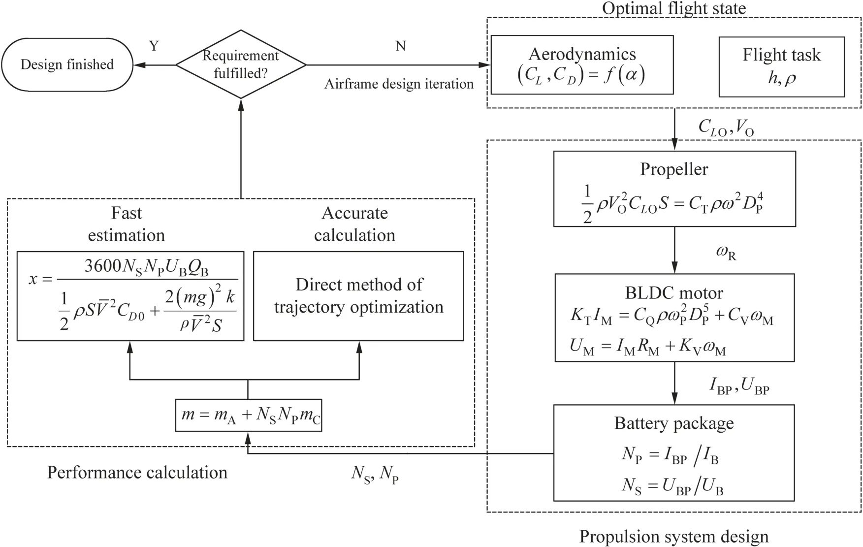
Fig.16 Battery package design optimization methodology.
(3) Including the dynamic feature of the electric system,the integrated approach based on the trajectory optimization provides a possibility to design the battery package topology according to the flight task and the electric system performance limits.The proposed methodology can be applied to more complicated maneuvers.
Declaration of Competing Interest
The authors declare that they have no known competing financial interests or personal relationships that could have appeared to influence the work reported in this paper.
Acknowledgement
The first author would like to thank China Scholarship Council for the support during his study and research.
杂志排行

CHINESE JOURNAL OF AERONAUTICS的其它文章
- Event-triggered control for containment maneuvering of second-order MIMO multi-agent systems with unmatched uncertainties and disturbances
- Adaptive level of autonomy for human-UAVs collaborative surveillance using situated fuzzy cognitive maps
- Coactive design of explainable agent-based task planning and deep reinforcement learning for human-UAVs teamwork
- Two-phase guidance law for impact time control under physical constraints
- Adaptive leader–follower formation control for swarms of unmanned aerial vehicles with motion constraints and unknown disturbances
- Optimal video communication strategy for intelligent video analysis in unmanned aerial vehicle applications