Design, assembly, and pre-commissioning of cryostat for 3W1 superconducting wiggler magnet
2020-12-08MiaoFuXuXiangZhenZhangRuiYeFuSanChenXiaoChenYangTongXianZhaoShaoPengLiXianJingSunLiangRuiSunChangChengMaRuiGe
Miao-Fu Xu· Xiang-Zhen Zhang · Rui Ye · Fu-San Chen·Xiao-Chen Yang · Tong-Xian Zhao · Shao-Peng Li · Xian-Jing Sun ·Liang-Rui Sun · Chang-Cheng Ma· Rui Ge
Abstract One of the most important devices for the High Energy Photon Source Test Facility project, the 2.6 T 32-pole 3W1 superconducting wiggler, was designed by the Institute of High Energy Physics (IHEP); its magnetic gap is 68 mm, and its storage energy is 286 kJ. It will be installed at the storage ring of the Beijing Electron Positron Collider Upgrade Project at the IHEP to replace the old permanent wiggler. The primary purpose of the cryostat is to create a safe and reliable system and realize long-term operation with zero liquid helium consumption. To maintain liquid helium temperature, four identical two-stage cryocoolers are placed symmetrically at the wiggler ends.The cryostat has only one 60 K thermal shield, which is used to reduce the heat load to the liquid helium vessel.The cryostat has several novel features, including a suspension system with little heat leakage that is self-centered during cooling of the cryostat, a special copper liner and high-efficiency condensers, three pairs of binary current leads, and three-level safety design. The cryogenic system has been cooled three times, and the residual cooling capacity is approximately 0.41 W at 4.2 K without current.
Keywords Cryostat · Cryocooler · Superconducting
1 Introduction
In low- and medium-energy storage rings for the generation of synchrotron radiation(SR),it is necessary to use high-performance insertion devices to meet the increasing demand for the high X-ray flux and characteristic energies needed to support the life sciences and material science.A strong magnetic field is needed because the maximum beam energy and beam current of existing storage rings cannot be optimized [1]. The superconducting wiggler is a state-of-the-art high-peak-field insertion device and is suitable for extending the spectral range of SR storage rings.
The performance of the cryogenic system strongly affects the service efficiency of superconducting wigglers.For example, a superconducting 63-pole wiggler was installed in the storage ring of the Canadian Light Source in January 2005; its average liquid helium consumption is 0.03 L/h in one running cycle [2]. A superconducting 49-pole wiggler was successfully tested at the diamond light source (DLS) site and installed in the storage ring in 2006; the average rate of liquid helium consumption was acceptable when the DLS was operated in decay mode,where the beam current is 250 mA. However, the liquid helium consumption increased significantly to 2.5 L/h when the DLS was operated in top-up mode, where the electron beam is topped up every 10 min to maintain the target current. A superconducting 2.1 T 119-pole wiggler was designed for the ALBA CELLS Light Source (Barcelona, Spain) and installed in the storage ring. The cryostat of this superconducting wiggler was designed to allow magnet temperatures of up to 3.5 K to ensure reliable system operation and zero liquid helium consumption[3, 4]. The 7.5 T multipole wiggler at the Center for Advanced Microstructures and Devices at Louisiana State University has generated SR since late 2012. Routine operation began in October 2014, and an insignificant rate of helium consumption has been observed [5, 6].
The 3W1 superconducting wiggler, with 32 poles and a period of 170 mm, was designed for the High Energy Photon Source Test Facility at the Institute of High Energy Physics(IHEP) and fabricated at Vacree Technologies Co.(Hefei, Anhui). Its maximum magnetic field is 2.6 T, and its running current is 350 A. It will be installed in the storage ring of the Beijing Electron Positron Collider Upgrade Project (BEPCII) at the IHEP to replace the old permanent wiggler, according to the mission statement.Therefore, the cryostat must fit into the tight space available in the existing BEPCII tunnel,which makes its design more challenging.
The cryostat is designed to support the cold mass accurately and reliably within the vacuum vessel, to provide all the required cryogenic pipeline and connectors, to insulate the cold mass from thermal radiation and conduction from the environment, and to include the cryocoolers. Three-dimensional design drawings of the cryostat are shown in Figs. 1 and 2.
The 3W1 superconducting wiggler magnet is placed in a special liquid helium cryostat with an operating temperature of 4.2 K.The available volume of liquid helium in the vessel without the magnets is approximately 160 L. The liquid helium vessel is surrounded by only one 60 K thermal shield to reduce the heat radiation from external sources. Four identical two-stage cryocoolers with cold head temperatures of 4.2 K/50 K are installed for thermal shield cooling and support. Two cryocoolers are symmetrically mounted at the top of the vacuum vessel and connected to the high-efficiency recondensers in the liquid helium vessel;they are used to re-liquefy helium gas that is vaporized by the heat load, maintain the operating temperature of the current leads during operation, and provide additional cooling of the 60 K thermal shield. The other two cryocoolers are symmetrically mounted at the bottom of the vacuum vessel and are used to cool the liquid helium vessel, which is covered by a highly thermoconductive copper net on the outside surface,and the 60 K shield.The vacuum pressure between the helium vessel and external warm stainless steel vessel, which can greatly reduce the heat flux, is 10-5Pa. The maximum length of the cryostat is 1989 mm, and the diameter of the vacuum vessel is 1024 mm.
2 Design details
2.1 Thermal design considerations.
The four identical cryocoolers mounted on the cryostat are operated as cold sources in the cryogenic system. The first-stage cold heads of the two cryocoolers installed symmetrically at the top of the cryostat are used to cool the warm ends of the high-temperature superconducting current leads and the 60 K thermal shield. The second-stage cold heads are used to cool the cold ends of the hightemperature superconducting leads and recondensers,which are used to re-liquefy vaporized helium gas. The first-stage cold heads of the other two cryocoolers, which are symmetrically installed at the bottom of the cryostat,are used to cool the 60 K thermal shield;their second-stage cold heads are used to cool the liquid helium vessel by heat conduction.The total cooling capacity of the cryocoolers is 6 W at 4.2 K and 200 W at 60 K according to the technical file provided by the manufacturer (Sumitomo Heavy Industries Ltd.).
In addition to meeting the mechanical design requirements, the cryostat is designed to minimize heat leakage owing to beam radiation and thermal conduction from the environment to the cold mass. Heat load to the cold mass greatly affects the operating cost of the magnet[7],and the superconducting magnet must be immersed in liquid helium to prevent heat transfer instability at the liquid/vapor interface. The heat load is well known to have three components: conductive heat, radiative heat, and convective heat. The conductive heat load can be greatly reduced by choosing appropriate materials, fully using the space inside the cryostat for cold mass support, employing thermal intercepts at 60 K, and providing high-vacuum insulation.The radiative heat load is reduced by employing the 60 K thermal shield and wrapping the cold mass in a multilayer super-insulating material. It is also important to keep the multilayer super-insulating material sufficiently dry and use the proper wrapping technique. There are 30 layers of superinsulation around the surface of the 60 K cold mass and 20 layers around the surface of the 4.2 K cold mass.The convective heat load is very low because of the good vacuum insulation between the helium vessel and external warm stainless steel vessel.
The heat load of the binary current leads is reduced by a high-temperature superconductor (HTS), which is cooled by the first stage of the cryocoolers. The calculated static heat loads of the stages at 4.2 and 60 K are summarized in Table 1.
2.2 Cold mass and suspension system
The 3W1 superconducting magnet was aligned at room temperature. However, the alignment of the superconducting magnet after cooldown is more important for users;thus, a special suspension system should be designed to avoid shifts in the magnetic plane [8]. The 3W1 superconducting magnet is placed inside the helium vessel and supported by the walls of the side flanges of the helium vessel using a special mechanism for controlling the position of the magnet body (Fig. 3). The mass of the magnet is approximately 960 kg, and the total mass of the 4.2 K cold mass is approximately 1350 kg. The helium vessel is suspended using eight racetrack-shaped strips,with four strips at each end. These strips make a 5° angle with the plane of the side flanges and attach to bolts on the external housing walls after passing through the 60 K thermal shield. Furthermore, they are used for precise alignment of the magnet position by adjusting nuts on the stainless rods from outside of the vacuum vessel without disassembling the cryostat and breaking the vacuum(Fig. 4). The position of the superconducting magnet can also be adjusted after cooling when there is no current.
These eight racetrack-shaped straps are made of carbon fibers (CFRP, T300). They have a very low conductivityto-yield-strength ratio at 4.2 K[9,10].The total theoretical heat load of the cold mass suspension system is 0.09 W at 4.2 K owing to the thermal interception at 60 K.To ensure the cryogenic and tensile performance of the straps,tensile tests at liquid nitrogen temperature were conducted using special test equipment (Fig. 5). The cross-sectional dimensions of the straps are 3 mm × 2 mm. The ultimate bearing capacity of each strap is 3.5 tons. The test results for the eight racetrack-shaped straps are shown in Table 2.
2.3 Radiation shield and special copper liner
The 60 K radiation shield, which is installed between the 300 K vacuum vessel and the 4.2 K helium vessel, is placed so as to intercept the radiative heat flow. The thermal shield is made of copper, which has a thermal conductivity of 528 W/m·K at 60 K, and cooled by the first-stage cold heads of the cryocoolers. A 60 K copper liner is installed between the beam tube and the 4.2 K vacuum chamber and is cooled by thermal conduction from 60 K heat sinks installed on both sides of the copper liner.Soft copper braids between the heat sinks and the 60 K copper shield ensure good thermal contact. To avoid thermal interference between the beam tube and 4.2 K vacuum chamber owing to the small gap, six pairs of special G10 supports are installed symmetrically on the top surface of the beam tube(Figs.6 and 7).The G10 supports do not touch the 60 K copper liner unless the liner is strongly deformed by gravity, thermal stress, and the Lorentz force caused by eddy currents.
The eddy currents caused by changes in the current may deform the copper liner owing to the Lorentz force [11].The most serious potential consequence is a large heat load due to thermal interference. Three approaches can be used to reduce the eddy currents. First, the rates at which the current increases and decreases as the magnet current is increased can be reduced. Second, slots in the top and bottom plates of the copper liner that are aligned according to the direction of the eddy current can be used to block the eddy current. Third, a suitable material can be chosen.According to a numerical electromagnetic simulation, the force on the top plate caused by the eddy current is significantly reduced by using slits (Fig. 8).
The cold mass and radiation shield are wrapped in 20–30 layers of superinsulation consisting of aluminized mylar with a mesh polyester interlayer(Figs.9 and 10).All the superinsulation should be placed in an oven for at least 6 h before wrapping to dry it sufficiently.

Table 1 Static heat load in 3W1 superconducting wiggler cryostat
2.4 Binary current leads and high-efficiency condensers
The superconducting wiggler coils are permanently welded to the current leads. The welded connections are the weakest point during magnet quenching because the superconducting coils are soft and have a low melting point. Therefore,flexible copper belts are used to weld the superconducting coils to reinforce the strength of the connection and provide overload protection. A pair of current leads with a current of 400 A are used for the main coils. Two other pairs of current leads with a current of 20 A are used for the correcting coils. These current leads are the main source of heat transfer to the cryogenic system by thermal conduction and joule heating[12].The property of current leads must have a low heat load, low discharge capacity, and modular structure, and they must protect against potential overload; therefore, binary leads consisting of copper and an HTS (Fig. 11), which operate in a vacuum and are cooled by cryocoolers, are chosen as the current leads for the cryostat.
To maintain good thermal contact and insulation, aluminum nitride (AlN) and indium pieces are used between the cryocoolers and current leads. The junctions betweenthe normally conducting and superconducting parts are cooled by the first-stage cold heads of the cryocoolers at 45–60 K. Both ends of the high-temperature superconducting current leads are connected to superconducting Nb–Ti coils using cryogenic electrical insulators and are cooled below 9 K by the second-stage cold heads of the cryocoolers.The temperatures at the top and bottom of the HTS are critical parameters; therefore, thermal probes are used to measure the temperature of the high-temperature superconducting current leads.The measurement is applied
to the wiggler interlock system.Additionally,the voltage at both high-temperature superconducting ends is monitored by voltage probes and monitoring software that was developed to measure the coil voltage and temperature and pass them to the magnet quench protection system [13].
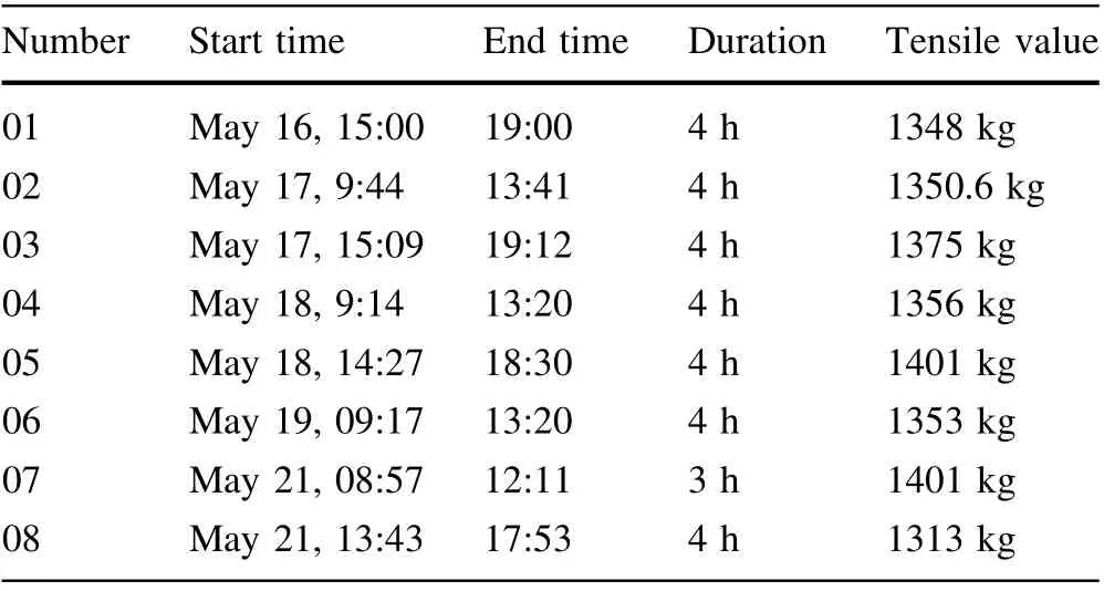
Table 2 Results of tensile performance tests of the straps
High-efficiency recondensers connected to the second stages of the cryocoolers are used to recondense the saturated helium gas inside the cryostat. A flow path is designed to minimize the temperature difference between the helium gas and the recondenser surface (Fig. 12).According to Nusselt’s membrane condensation theory for a pure saturated vapor layer, the mean temperature difference ΔTcΔTcΔTcof the condensing surface is [14, 15]
2.5 Service tower and instrumentation
The service tower at the center of the top of the vacuum vessel contains the instrumentation wires, voltage taps,automatic pressure relief valve, pressure sensor, safety relief valves, and feedthroughs. A 60 K intercept is installed between two bellows to reduce the heat load. To cool the magnet slowly and homogeneously, liquid helium is injected through the cryogenic pipeline from a mobile helium dewar and diverted through a pipe to the bottom of the helium vessel (Fig. 14). To minimize the heat load,nine thermal baffles are installed at equal distances using three G10 supports connected to the top flange of the service tower.The wiring for the temperature sensors,quench protection system, and lever sensors are exited from the service tower.
When the magnet is quenched,approximately 100 kJ of storage energy is released to the cryogenic system in 5 s;therefore, helium evaporates at a rate of 6545 kg/h. The helium pressure increases immediately and reaches a peak value of 2.3 bar. The service tower is equipped with an automatic pressure relief valve, six DN15 safety relief valves, and a DN60 burst disc to ensure that the helium is discharged rapidly in the event of magnet quenching or cryogenic failure (Fig. 15). The automatic pressure relief valve is set to a pressure of 1.2 bar, which corresponds to 4.4 K saturated liquid helium, and can be adjusted manually. The safety relief valves and burst discs are set to pressures of 5 and 6 bar, respectively.
Two identical liquid helium-level sensors are installed on the side of the flange inside the helium vessel; one is used, and the other serves as a backup. Two identical temperature sensors are installed on the top surface of the magnet to ensure that the magnets are completely immersed in liquid helium.To ensure the safe operation of the superconducting magnet, the liquid helium level and magnet temperature signals are passed to quench the interlock system.
2.6 Vacuum system
It is very important to maintain good vacuum insulation to minimize the heat load during the operation of the cryogenic system of the 3W1 superconducting wiggler.The cryostat has three separate vacuum systems. The insulation vacuum, which has a pressure of 10-5Pa, can reduce the heat load by conduction from the warm external stainless steel vessel to the helium vessel. The beam tube vacuum must provide an ultrahigh vacuum to afford a long beam lifetime and low background for experiments. In addition, the cryogenic pipeline, which is used to automatically discharge cold helium gas during quenching of the superconducting magnet,requires an insulation vacuum to prevent freezing of the flanges at the service tower.
A turbomolecular pump is used to provide the insulation vacuum of the cryostat.After the insulated space inside the cryostat is pumped to 10-3Pa at room temperature, the four cryocoolers can be started up to cool the thermal shield and cold mass.When the thermal shield is cooled to approximately 100 K, liquid helium can be injected into the helium vessel at a low flow rate to reduce the total time needed to cool from room temperature to 4.2 K. When the cryostat is completely cooled and liquid helium inside the helium vessel has reached the design level, the turbomolecular pump should continue operating to maintain the insulation vacuum at a pressure of 10-5Pa to compensate for air escape from the superinsulation.
The beam tube requires ultrahigh vacuum during beam operation.It should be pumped to 10-8Pa at the operating temperature by a set of ion pumps. An independent turbomolecular pump was used to provide the vacuum in the beam tube during pre-commissioning.
The cryogenic pipelines are pumped to 10-3Pa at room temperature before cooling, and the insulation vacuum is then sealed using special connectors. An ion pump should be connected to the downstream beam tube to pump the gas load induced by SR from the 3W1 superconducting wiggler and bending magnet [16].
3 Assembly and pre-commissioning
3.1 Assembly
The cryostat can be divided into six subassemblies: the vacuum vessel, base support, 60 K copper shield, helium vessel, service tower (used for injecting liquid helium and instrumentation),and installation tower(used for installing the cryocooler and current lead). The component quantity and quality were checked and the components were washed carefully using pure alcohol before assembly. After the component vacuum leak check, cold shocking of the cryogenic subassemblies and pressure testing of the pressure components were performed throughout the fabrication and assembly of the cryostat.
The subassemblies were installed first,and pre-assembly was performed to ensure that there is sufficient space as specified by the design and to avoid thermal contact between different temperature zones. Indium pieces and N grease (Aplezon) were used to maintain good thermal contact between different components in regions at the same temperature.
The assembly sequence is as follows.
Step 1 Assemble the vacuum vessel and base support during pre-assembly; then finish installing the installation tower and service tower (Fig. 16). Note that the service tower should be used to perform an independent cryogenic test to check the seal at 77 K.
Step 2 Move the 60 K copper shield into place and ensure that there is no thermal contact with the vacuumvessel. Install the helium vessel subassemblies by special tooling, including the mounting of the eight carbon fiber strips that pass through the copper shield and are connected to the external cryostat vessel. At the same time, align the magnet precisely by adjusting the nuts on the stainless rods from outside of the vacuum vessel (Fig. 17).
Step 3 Remove the temporary supports from the helium vessel, and carefully install the installation tower and service tower subassemblies. Finish the end interconnection between the service tower and helium vessel,and then weld the high-temperature superconducting end to the cryogenic electrical insulators at 400 A and 20 A(Fig. 18).
Step 4 Wrap the end flanges of the thermal shield in 30 layers of multilayer superinsulation consisting of aluminized mylar with a mesh polyester interlayer (Fig. 19).Finally, perform a vacuum leak check by using a helium mass spectrometer leak detector.
3.2 Pre-commissioning
The pressure of the helium vessel is crucial to safe operation and maintaining the magnet operating temperature, especially during magnet quenching. One automatic pressure relief valve is installed to regulate the recycling of the cold helium gas. To protect the cryostat and magnet,the automatic pressure relief valve can be opened automatically in the event of high helium pressure in the helium vessel, a quench protection signal, or poor insulation vacuum in the cryostat. The normal operating pressure is set between 1.2 and 1 bar, and it can be adjusted manually if necessary. The signals of the quench protection system,helium vessel pressure,and automatic pressure relief valve are interlocked.
The cryogenic system of the 3W1 superconducting wiggler was cooled successfully at the Vacree site (Hefei,Anhui) in September 2018. The current of the magnets reached the design value of 350 A after four training magnet quenches. To reduce the cooling time, liquid helium was injected at a low flow rate after the thermal shield was cooled to approximately 100 K by the cryocoolers alone. Cooling from room temperature to liquid helium temperature required 5–6 days (Fig. 20), and the total liquid helium consumption during cooling was approximately 1000 L.
Residual cooling capacity tests were performed using a heater installed inside the helium vessel shell after the cryostat was cooled completely. The residual cooling capacity of the cryogenic system is approximately 0.41 W without current. The measured heat load to the liquid helium vessel is larger than that predicted by theoretical calculations. The current of the superconducting magnet was increased at a specified rate when the power and quench protection systems were ready (Fig. 21). The monitoring curves show that the cryogenic system has little residual cooling capacity at an operating current of 320 A.One to three training quenches occurred while we performed repeated cryogenic tests. The cryogenic system tended to be stable and reached thermal equilibrium after 24 h at a magnet current of 320 A (Fig. 22).
The average temperature of the thermal shield is 60 K at a magnet current of 320 A according to temperature field analysis, which is higher than the value predicted by a numerical simulation. The heat transfer temperature difference between the first-stage cold heads of the cryocoolers installed at the bottom of the vacuum vessel and the thermal shield is 20 K;thus,the full cooling capacity of the cryocooler is not used. Three factors should be considered. First, the quality of the installation, especially the connectors between the cold heads and copper belts,should be checked.Second,the thermal conductivity coefficient of the copper may be below the value required by the contract, the material performance should be retested later to determine the reasons.Third,the thermally conductive area may not be large enough.
The magnetic field integral is adjusted using correcting coils. The first and second magnetic field integrals are obtained using a tension line measuring system. The first field integral decreased from -636 to 9.3 G·cm at an operating current of 320 A, and the second field integral decreased from 223,432 to -3324 G·cm2. The obtained magnetic field integrals show that the magnets with the correcting coils were cooled and operated normally. In particular,the quality of the 20 A current lead and the antivibration structure meet the requirements for superconducting magnets.
4 Improvements and testing
The cryogenic system for the 3W1 superconducting wiggler has passed preliminary cryogenic tests performed at the manufacturing site.The test results confirmed its full operability. The total cooling time from room temperature to liquid helium temperature is ~5–6 days. Pre-commissioning demonstrated the reliability of the protection system during superconducting quenching of the magnet.However,the measured heat load to the liquid helium bath is larger than that predicted by theoretical calculations.It is necessary to improve and optimize the cryostat on the basis of the data from pre-commissioning before it is transported to the IHEP site.
The measured heat load to the liquid helium tank and the temperature differences between the cryocooler stages and cooled objects were larger than those predicted by theoretical calculations (Fig. 23). The full capacity of the cryocoolers was clearly not exploited, and the average temperature of the thermal shield was higher than the predicted value. Three things should be considered: the heat conductivity of the copper component, the cross-sectional area for heat conduction,and the thermal insulation.
The residual resistivity ratio (RRR) of the thermoconductive copper cylinder used to extend the stages of the cryocoolers was measured using the fixed point method[17]. The results showed that the RRR of the thermoconductive copper cylinder installed in the cryostat was lower than that required by the contract with the manufacturer.A new cylinder was manufacturing using better and thicker copper to reduce the temperature difference and was installed to replace the old one.Photographs of the old and new copper cylinders with their RRRs are shown in Fig. 24.
Flexible copper braids were used to connect the thermoconductive copper cylinder to the 60 K thermal shield,and new flexible copper braids were added to reduce the temperature difference between the cryocooler stages and the cooled objects as much as possible, especially the thermal shield and the surface of the helium vessel(Fig. 25).
The insulation material used in the cryostat is doublealuminized mylar with a double silk net and ten layers per unit. The mean temperature of the copper shield is very important for reaching the goal of zero liquid helium consumption [18–20]. Equation (2) describes the heat flux of the copper shield.
The service tower provides a transfer port for the electrical equipment, liquid helium inlet port, gas return,pressure gauge, safety valves, and other components. A 60 K thermal intercept, which is connected to the 60 K thermal shield by flexible copper braids, is installed between two bellows to reduce the heating by thermalconduction. The pressure of the helium vessel sometimes rises immediately for some reason, especially during magnet quenching, and the automatic pressure relief valve can open immediately to discharge the pressure in the helium vessel when it exceeds the set point.The maximum operating pressure of the helium vessel is approximately 2.1 bar according to the pre-commissioning data. The old bellows,which were installed in the service tower and have an operating pressure of 8 bar, are too thick to reduce the heat load, even though a 60 K intercept was installed between the two bellows to reduce the heat conduction to the helium bath. The designed selection pressure of the new bellows is 5 bar,and the thickness of the new bellows was reduced from the original value of 1.2 mm to 0.8 mm according to a calculation;in addition,the wave number of the bellows was increased from 5 to 12 (Fig. 26). The
temperature field distribution of the service tower was calculated using ANSYS 14,and the heat load was found to be approximately 0.7 W at 4.2 K (Fig. 27).
A two-layered,vacuum-jacketed stainless steel tube was designed to stop the transfer port from freezing during helium gas return to the recovery system,especially during magnet quenching. To reduce the heat load of residual gas heat conduction, a length of approximately 350 mm was selected for the tube inside the cryostat according to the optimal design and calculation. In addition, a special helium gas flow channel to the safety valves and burst disc were designed (Fig. 28).
Approximately 2 months were needed to improve and optimize the cryostat because high-thermoconductivity copper and new components had to be prepared. The cryogenic test of the cryostat began in May 2019. The test results show that the mean temperature of the thermal shield was decreased from 60 to 45 K. The temperature difference between the first stage of the cryocoolers and the thermal shield was decreased from 20 to 4.5 K (Fig. 29).The residual cooling capacity of the cryogenic system was approximately 0.7 W at 4.2 K when the operating current of the magnet was 320 A,and it was retained for more than one month. The cryogenic system was clearly improved and optimized successfully and can meet the requirements for stored beam operation.
5 Conclusion
The cryogenic system of the 3W1 superconducting wiggler was successfully improved and optimized, and the goal of zero liquid helium consumption was met. The residual cooling capacity of the cryogenic system is approximately 0.7 W at 4.2 K when the operating current of the magnet is 320 A, and it was retained for more than one month; this capacity is 12% of the total cooling capacity of the cryogenic system.The system can meet the minimum requirements for the nominal operating conditions of the storage ring to accommodate the beam-induced heat loads [21] and the degradation of the cryocooler operating efficiency with time [22].A cryogenic test using a tension line measuring system showed that the first and second magnetic field integrals satisfied the design requirements. The cryostat of the 3W1 superconducting wiggler was installed in the storage ring of BEPCII to replace the old permanent wiggler in November 2019.
AcknowledgementsThe authors thank Dr. Cheng-Lian Liu at the Institute of Plasma Physics, Chinese Academy of Sciences, for his technical support of the binary current leads. They are also grateful for the experimental conditions and experimental guidance provided by the cryogenic group of IHEP.
杂志排行

Nuclear Science and Techniques的其它文章
- Analytic RF design of a linear accelerator with a SLED-I type RF pulse compressor
- Preliminary analysis of fuel cycle performance for a small modular heavy water-moderated thorium molten salt reactor
- Effective (kinetic freeze-out) temperature, transverse flow velocity, and kinetic freeze-out volume in high energy collisions
- Simulation-based correction of dose enhancement factor values in photon brachytherapy with metal nanoparticle targeting
- Preliminary evaluation of the radiotherapeutic efficacy of 131I-atorvastatin in rats with hepatocellular carcinoma
- Design of a 162.5 MHz continuous-wave normal-conducting radiofrequency electron gun