Effect of insulating oil covering electrodes on the characteristics of a dielectric barrier discharge
2020-11-10TrungNguyenTRANBounyangOANTHAVINSAKShinichiroKADOandHirotoMATSUURA
Trung Nguyen TRAN,Bounyang OANTHAVINSAK,Shinichiro KADO and Hiroto MATSUURA
1 Department of Quantum and Radiation Engineering,Graduate School of Engineering,Osaka Prefecture University,Sakai,Osaka 599-8570,Japan
2 Institute of Advanced Energy,Kyoto University,Uji,Kyoto 611-0011,Japan
Abstract
Keywords:atmospheric pressure plasma jet,APPJ,Lissajous figure,dielectric barrier discharge,plasma plume
1.Introduction
The atmospheric pressure plasma jet(APPJ)is receiving a great deal of attention because it is applicable in various agricultural and medical fields.APPJ techniques have a relatively high electron temperature which can produce active radicals such as reactive nitrogen species and reactive oxygen species(ROS).APPJ is a promising technology for both current and future applications.The optimization of atmospheric pressure discharge can overcome most of the disadvantages of vacuum system equipment[1-5].
In particular,a two-electrode plasma source,where the dielectric prevents the formation of high-temperature sparks,is the most widely used atmospheric pressure plasma device.Although it is easier to obtain a uniform glow discharge with pure helium as the primary plasma-forming gas[6],its disadvantage is the limitation of the supplied voltage and the generation of a spark between two electrodes,leading to stop plasma discharge.Adjustment of the electrode configuration is still ongoing,along with gas flow optimization.Recently,Nguyen et al[7]proposed a method where two ring electrodes are immersed in electrically insulating oil.This prevents arc formation compared with electrodes exposed to ambient air.Based on these ideas,the discharge power and plasma jet length were investigated by our plasma device.In addition,ROS production was evaluated with a new chemical probe.
2.Experimental methods
2.1.Types of plasma source and electrical circuit
Figure 1 shows a schematic configuration of the coaxial dielectric barrier discharge(DBD)plasma source.The glass tube with two ring electrodes has an inner radius of 4 mm,outer radius of 5 mm and axial length of 180 mm(figure 1(a)).The electrodes are the copper tape covering the outside of the glass tube;the widths of the power and ground electrodes were set to 30 mm and 10 mm,respectively.The distance between these electrodes was 5 mm.In particular,figure 1(b)shows that the electrodes were completely covered with an electrically insulating oil(transformer oil,Shin-Etsu silicon,KF-96-10CS,Japan).KF-96 is a silicone fluid with a dimethylpolysiloxane structure.KF-96 makes up highly heatresistant materials such as glass and quartz.KF-96 is exceptionally stable with regard to thermal oxidation,and there is almost no change from room temperature to 150°C.The volume of the insulating oil is 318 ml.

Figure 1.Schematic of the experimental setup;(a)two ring electrode configuration and(b)insulating oil covering two ring electrode configuration.

Figure 2.Signal of applied voltage and charge on the electrode;(a)no oil with supplied voltage at 5 kV and(b)insulating oil with supplied voltage at 5 kV.

Figure 3.The effect of applied voltage on the plasma jet length.
The transformer device(110 V,12 A,Variac)is connected with the input of the power supply(LHV-13AC,Logy Electronics Ltd)to control its input voltage.The power ring electrode is connected to the output of the voltage supply.A high-output voltage power supply is used to charge a 5 μF capacitor through a 50 Ω resistor in the circuit system.A high-voltage supply with a low frequency of 10 kHz was applied in this study.The resistor measured the discharge current on the electrode passing through the circuit.Furthermore,the resistor is also used to protect the electric system from high short current.Lissajous figure analysis[3]is conducted by the capacitor,which measures the accumulated charge and high-voltage probe(Tektronix P6015A,10FT cable,75 MHz),which measures the applied voltage across a power electrode and a ground electrode.Three voltage signals are acquired by a digital oscilloscope(TDS 2014,Tektronix)[6].
The ground electrode temperature is measured by thermocouples which are connected to a data logger.Thermocouples are connected through an isolation amplifier to prevent electromagnetic noise from the power supply.This improves the accuracy of the experimental results.The helium gas flow rate is 2 l·min−1.

Figure 4.True-color photographs of plasma jets generated by using insulating oil covering two ring electrodes.
2.2.PVA-KI gel and measurement
In[8],a polyvinyl alcohol-potassium iodide(PVA-KI)compound was used as a radiochromic gel indicator.PVA-KI is mainly composed of PVA(laundry paste),borax,potassium iodide and distilled water.PVA-KI may form a nontoxic,low cost,reusable,highly efficient dose meter.It is easy to use and has excellent characteristics for visualization of radiation in gel form[9].In addition,its form is easily modified from liquid to gel by changing the concentration of water.The PVA-KI color changes to red with high sensitivity by radiation dose,although it can be recovered by the heating method(over 45°C),thus being reusable.This chemical compound is proposed as a new chemical probe to study ROS production by plasma irradiation.
The compositions of the PVA-KI samples used in this work contain water of 250 ml,PVA of 10 ml and KI of 12.5 g.Absorbance spectra were measured at room temperature using a spectrophotometer(Hitachi U-2001)with a wavelength of 350-600 nm.
3.Results and discussion
3.1.Plasma jet generation
Figure 2 shows the signals of applied voltage and charge on the electrode.From figure 2(a)we noticed that the stable plasma discharge is limited to 5 kV supplied voltage due to spark generation.Two parameters that affect the generation of sparks are high supplied voltage and a small gap between electrodes.
According to figure 1(b),an insulation oil bath was constructed to contain a plasma jet device,and cover the power and ground electrodes.Figure 2(b)shows the voltage and current waveforms; the small spikes have disappeared with an insulation oil coverage under the same conditions.This makes the applicable voltage range wider.
The plasma jet length depends on many irradiation conditions such as the feed gas,gas flow rate,humidity and plasma configuration[10-14].
Figure 3 shows the effect of the applied voltage on the plasma jet length.The red circles are for the operation with electrodes in ambient air,and the black squares are in the insulating oil.The relation between the applied voltage and jet length is compared in both configurations.It is seen that the plasma jet length increased from 0 to 13 mm in ambient air with supplied voltage from 3 to 5 kV,respectively.However,we could not obtain a stable plasma jet with a supplied voltage over 5 kV in ambient air[15,16].
The plasma jet length can be enhanced by covering the electrodes with insulating oil.We can easily increase the supplied voltage without sparks between the two electrodes.The plasma jet length can be longer than 25 mm under high applied voltage conditions(>8 kV)using insulating oil,although the jet length for low applied voltage is the same even with insulating oil covering the electrodes of the plasma source.
Figure 4 shows true-color photographs of the plasma jets generated by using insulating oil covering the two ring electrodes under four different supplied voltages:4 kV,5 kV,7 kV and 8 kV.The smaller gap makes plasma production possible with a smaller voltage.The insulation oil expands this high efficient production limit.

Figure 5.The area of Lissajous figure with/without oil.
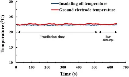
Figure 6.Temperatures of insulating oil and ground electrode.

Figure 7.Photographs and absorbance spectra of PVA-KI samples at different voltages with no insulating oil;(a)PVA-KI samples irradiated at different voltages without oil and(b)absorbance spectra of PVA-KI samples at different voltages without oil.
3.2.Discharge power estimation
The consumed power between the insulating oil plasma configuration and the conventional configuration has been compared under the same operating parameters.The absorbed electric power to sustain discharge can be estimated with the Lissajous figure method[17-19].Figure 5 shows areas of the Lissajous figure with and without insulating oil.The consumed power is determined by multiplying the area of the Lissajous curve by the frequency(10 kHz)applied to the system[6].The effects of insulating oil and applied voltage on the characteristics of Lissajous figures are investigated[20,21].In both cases with/without insulating oil configurations,the Lissajous figure area is similar at a supplied voltage of 5 kV.In this work,only helium gas is used with standard 2 l·min−1,and the consumed power by the APPJ device is about 60 W when the supplied voltage is increased from 5 to 6 kV.There is a limit of applied voltage distance between the two electrodes,above which sparks occur and stable operation is lost.When the insulating oil is used,the consumed power is increased from 60 to 75 W,corresponding to the change of the area of the Lissajous figure.Clearly,this method can be enhanced by the supplied voltage as well as the consumed power.
Figure 6 illustrates that with 10 min irradiation time,the ground electrode temperature was kept at about 22.5°C.The insulating oil temperature ranged from 22.3 °C to 22.8 °C during irradiation time with the applied voltage at 5 kV and helium gas flow rate at 2 l·min−1.The heat generated around the ground electrode is negligible and does not cause a change in the chemical structure of insulating oil.

Figure 8.Photographs and absorbance spectra of PVA-KI samples at different voltages with insulating oil;(a)PVA-KI samples irradiated at different voltages with oil and(b)absorbance spectra of PVA-KI samples at different voltages with oil.
3.3.PVA-KI absorbance spectra
To investigate the ability of the APPJ to produce ROS in the liquid water[22-26],we irradiated the PVA-KI liquid samples.When there are ROS in the sample,iodine ions are oxidized and compose colored composite with PVA.Even a small color change can be detected from the absorption spectra.In the radiation chemistry field,this reaction was reported early,and a new chemical dose meter using an absorption peak at the specific wavelength was proposed recently.Our proposal to use PVA-KI as a chemical probe will be reported elsewhere.
Figure 7 shows the photographs and absorbance spectra of PVA-KI samples at different voltages with no insulating oil.The distance from the nozzle of the glass tube to the liquid surface is 20 mm and the helium gas flow rate is 2 l·min−1.The plasma jet does not directly touch the solution surface.The absorbance peak is measured by the amount of radical generation reacting with PVA-KI.To test the dependence of the amount of radical generation on the supplied voltage,absorption peaks were measured at around 390 nm.
Figure 7(a)shows the PVA-KI chemical probe color as they were irradiated by plasma produced with 5 kV,6 kV and 7 kV.The PVA-KI solution was irradiated in a glass beaker of 20 mm diameter and 30 mm height for 1.5 min.The amount of the solution was 10 ml.Concerning the plasma irradiation supplied voltage,the color of the solution became yellow when the supplied voltage was increased from 5 kV to 7 kV.As the absorbance spectra increased,the solution gradually changed from colorless to red.Figure 7(b)shows the absorbance spectra of the solution.A prominent absorption peak was observed at 390 nm.When the applied voltage was raised from 5 kV to 7 kV,the intensity of the absorbance spectra was increased,respectively.The results illustrate that the absorbance spectra of PVA-KI change with different supplied voltages.
Figure 8 shows the effects of insulating oil on the PVAKI color change at different voltages.With insulating oil,the supplied voltage can be easily increased from 5 kV to 9 kV without spark generation.Figure 8(a)shows photographs of the PVA-KI solution after plasma jet irradiation for 1.5 min with supplied voltage from 5 kV to 9 kV.The color change was increased with the increased voltage.The color of the solution changed from colorless to red.
At a high supplied voltage leading to a longer plasma jet,there will be more reactions of plasma with the surface of samples and ambient air.Therefore,radical generation can be enhanced[27-30].Figure 8(b)shows the absorbance spectra of PVA-KI responses with different applied voltages.
Figure 9 shows that the radical amount produced by plasma irradiation increases linearly with applied voltage.Since insulating oil expands the applicable voltage limit,it also has a good effect on radical production.However,further radical amount calibration and evaluation of its fundamental characteristic will be needed.The calibration results of the PVA-KI sample will be reported in the near future.

Figure 9.The relationship between absorption peak(390 nm)and supplied voltage with/without oil.
4.Conclusions
A dielectric barrier plasma jet source with two ring electrodes was improved by covering the electrodes with insulating oil.The plasma jet performance was measured with the jet length and radical production.The plasma jet length can be increased with applied voltage.Radical production was monitored by a plasma-irradiated PVA-KI sample absorption peak,and it also increased with the applied voltage.There is a limit of applicable voltage between two electrodes,above which sparks occur and stable operation is lost.By using insulation oil,this limit can be expanded.From preliminary observation,a narrow gap configuration was found to reduce the ignition voltage.Further research on this configuration would bring more effective plasma and radical production.
Acknowledgments
This work was partially supported by the ZE Research Program,IAE(ZE31B-23)and the joint usage/research program,cLPS(19022).
ORCID iDs
杂志排行

Plasma Science and Technology的其它文章
- Density limit disruption prediction using a long short-term memory network on EAST
- Research on the real-time signal conditioning method for dispersion interferometer in HL-2M
- Development and performance characterization of a compact plasma focus based portable fast neutron generator
- Dynamic heating and thermal destruction conditions of quartz particles in polydisperse plasma flow of RF-ICP torch system
- Numerical investigation on electron effects in the mass transfer of the plasma species in aqueous solution
- Design and characteristics of a triplecathode cascade plasma torch for spheroidization of metallic powders