Uplink NOMA signal transmission with convolutional neural networks approach
2020-11-01LINChuanCHANGQingandLIXianxu
LIN Chuan,CHANG Qing,*,and LI Xianxu
1.School of Electronic and Information Engineering,Beihang University,Beijing 100191,China;2.State Grid Information and Telecommunication Branch,Beijing 100761,China
Abstract:Non-orthogonal multiple access(NOMA),featuring high spectrum efficienc,massive connectivity and low latency,holds immense potential to be a novel multi-access technique in fifth generation(5G)communication.Successive interference cancellation(SIC)is proved to be an effective method to detect the NOMA signal by ordering the power of received signals and then decoding them.However,the error accumulation effect referred to as error propagation is an inevitable problem.In this paper,we propose a convolutional neural networks(CNNs)approach to restore the desired signal impaired by the multiple input multiple output(MIMO)channel.Especially in the uplink NOMA scenario,the proposed method can decode multiple users’information in a cluster instantaneously without any traditional communication signal processing steps.Simulation experiments are conducted in the Rayleigh channel and the results demonstrate that the error performance of the proposed learning system outperforms that of the classic SIC detection.Consequently,deep learning has disruptive potential to replace the conventional signal detection method.
Keywords:non-orthogonal multiple access(NOMA),deep learning(DL),convolutional neural networks(CNNs),signal detection.
1.Introduction
With the growth of users’demand for higher communication speed and Internet of Everything,the need for massive connection and high throughput has been put forward.Unlike the conventional orthogonal multiple access(OMA)commonly used in the fourth-generation(4G)communication system,the non-orthogonal multiple access(NOMA)technique can improve the spectrum efficiency effectively via the non-orthogonal superposition of the signal power.Hitherto,the power-domain NOMA has evolved into codedomain and hybrid-domain NOMA,such as multi-user shared access(MUSA),sparse code multiple access(SCMA),and pattern division multiple access(PDMA).Here,we focus on uplink power-domain NOMA systems for its representativeness and universality.
Successive interference cancellation(SIC)is a classic and effective method for signal detecting.For both uplink and downlink,SIC for NOMA signal detection provides an optimal scheme to realize the maximization of the multiuser capacity[1].The fundamental of SIC is that user equipment(UE)with worse channel state should be allocated with higher power and it should be decoded with higher priority at the receiver while other UE signals are treated as interference.Then the decoded signal needs to be modulated again and removed from the received signal so that the next highest priority UE signal can be restored.According to the descending order of power,the decoding procedure of other UE signals will be carried out as mentioned above until the desired UE signal is obtained.The NOMA-SIC receiver has its shortcomings.On one hand,the high throughput is obtained at the expense of system complexity which increases with the UE numbers.On the other hand,the error will be accumulated during the process of SIC.
Inspired by the power of deep learning(DL)changing the world profoundly,we explore its power in the NOMA signal detection.So far DL technology has had great success in many areas and diversities of new structures are proposed.Deep neural networks(DNNs)are the most classic DL forms to enhance the neural networks(NNs)performance by deepening the number of layers and neurons,and many successful applications can be seen in pattern classification and recognition.For natural language processing(NLP),recurrent neural networks(RNNs)are also formidable tools to handle signals among which sequences are related with each other.Another famous type of DL is conventional neutral networks(CNNs).Its unique convolutional layer and pooling layer reduce sharply the computation complexity of image processing.
Successful commercial applications using the learning approach in wireless communication are much fewer[2].However,steps of related scientific study never stop.Many successful examples have been reported in various parts of communication,such as channel decoding[3–5],compressed sensing[6],detection for multiple input multiple output(MIMO)[7–9]and orthogonal frequency division multiplexing(OFDM)system[10],and modulation classification and identification[11].Preliminary explorations on NOMA with the DL method have made progress in recent years.DL can optimize the power allocation of NOMA UEs.Saetan et al.completed the power allocation for downlink NOMA system with DL and results verify the near optimal performance with low computational complexity[12].Zhang et al.investigated the energy-efficient resource allocation under joint subcarrier assignment and power allocation for uplink NOMA with reinforcement learning[13].For multi-carrier NOMA,the problem of power allocation and channel assignment with the reinforcement learning framework were studied in[14].The power allocation scheme in[15]was ruled by sum rate maximization in NOMA-SIC with DNN and its sum rate performance was close to the optimal scheme but with lower complexity.The NOMA transmission can also be designed as an end-to-end DL system.Ye et al.regarded the overlapped NOMA transmissions as multiple distinctive but correlated learning tasks.An end-to-end NOMA with the DNN form was proposed in[16].An end-to-end transmission system with long short term memory(LSTM)network for uplink NOMA was reported in[17].Kang et al.utilized the DNN for precoding at the transmitter and decoding at the receiver[18].Several deep feed forward neural networks are adopted to fit the SIC processing.Although the autoencoder system shows excellent performance for its global optimization,it is hard to train the parameters of transmitting and receiving ends simultaneously in most realistic scenarios.
Undoubtedly,DL technology will not succeed without the rapid development of the graphic processing unit(GPU).Google has announced three generations tensor processing units(TPUs)from the first generation in May 2016 to now.The cost could be lowered by 80%for the third-generation TPUs.The newest TPU Pod can be configured with more than 1 000 TPUs and its computational speed reaches 100 peta flops.Although GPU resources remain expensive for users,the price continues to decrease in accordance with the Moore’s law.
As mentioned above,the traditional SIC has the problems of error propagation and high complexity.Besides,the long delay is inevitable for the process of SIC,especially in situations of large numbers of UEs.To handle these problems,we proposed a deep learning approach for uplink NOMA detecting.In our early work,we have explored the power of DNN in downlink MIMO-NOMA signal detection[19].To fully tap into the potential of the DL method,we propose a learning approach based on CNN to detect the uplink NOMA signal without any traditional communication signal processing steps.Unlike the downlink NOMA based on DNN,the uplink NOMA system with CNN transfers the cost of hardware into base station(BS),which is much stronger than UEs in terms of signal processing.The structure of groups output can deal with multiple UEs’detection very well at BS.Results reveal its excellent detection performance and signal processing ability.
The main contributions of this paper are summarized as follows:
(i)We design the first CNN detection system for the uplink NOMA system.The received NOMA signal can be processed by CNN completely instead of the traditional SIC method.
(ii)We make the utmost of CNNs power to handle highdimensional information.The proposed system is able to fix the impairment from MIMO Rayleigh fading channel intelligently and accomplish the complex procedure of multiple UEs demodulation and decoding.
(iii)To evaluate the proposed system,we provide comparable simulations to SIC.The CNN method has a better error performance and lower computation complexity.
The structure of remainder is organized as follows.The preliminaries of NOMA and CNN are reviewed in Section 2.Then,the NOMA with the CNN approach called“Dense NOMA”is depicted in Section 3.Numerical simulation is provided in Section 4.Finally,we summarize the research and look to the future work in Section 5.
2.Preliminaries
The basic knowledge of proposing DL system for NOMA detection mainly involves two parts:uplink NOMA transmission and CNNs.Here,we introduce briefly both parts.For simplicity,the bandwidth is assumed to be 1 Hz and the channel is composed of additive white Gaussian noise(AWGN)and Rayleigh fading channels.
2.1 Uplink NOMA transmission
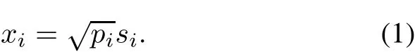
In this subsection,we describe the basic principle of uplink NOMA.Unlike the traditional OMA where different UEs occupy orthogonal time-frequency resources,NOMA can further enhance the spectrum efficiency by superposition coding to implement the message overload transmission.In the uplink,suppose the antenna numbers of UEs and BS are 1 andNrrespectively,andNtis the number of UEs.siandpiexpress theith UE signal and its power respectively.Thus theith NOMA signal can be expressed as
At the BS,the received signal of thejth antenna can be represented as

wherehijis the channel gain from theith UEito UEj.The matrix form of(2)is

wherex= [x1,x2,...,xN]is the UE signal,channel matrix,is the channel gain from theith UE signal to thejth BS antenna andw=[w1,w2,...,wNt]Tis the AWGN channel.
The schematic of the uplink NOMA system can be seen in Fig.1.
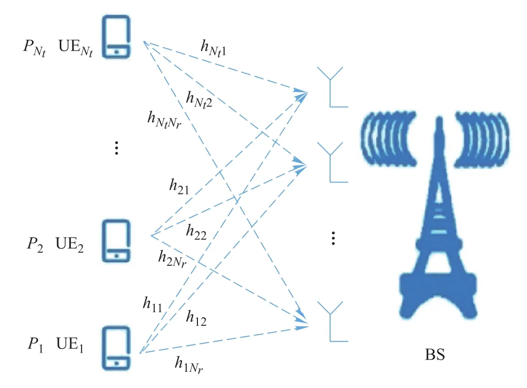
Fig.1 Schematic of the uplink NOMA system
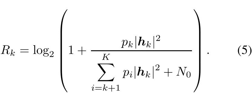
At the BS,the SIC mechanism is operated.The receiver decodes signals in multiple stages according to the desired UE power.In the first stage,signals with the highest power will be decoded while the others are treated as interference.The throughput of theith UE can be expressed as

Then the restored message should be remodulated and subtracted from the received signal so that the second stage can be carried out to decode the signal of the second highest UE power.This process continues until thekth desired signal has been decoded.The throughput of thekth UE is represented as
The diagram of minimum mean square error(MMSE)with SIC can be seen in Fig.2.Undoubtedly,the error of the higher decoding priority signal has a tremendous impact on the lower priority signal,and these errors continue propagating with the SIC process.The complicated workflow of SIC increases the complexity of the receiver.

Fig.2 Schematic of SIC receiver
2.2CNNs
Recently,DL technology has become one of the hottest issues.Most of DL frameworks are originated by NN,which is constituted bymany hierarchical neurons. Different from the DNN which merely increases the number of neurons and the depth of hidden layers to improve the learning ability, CNN provides a novel structure for massive data processing. In general, a CNN consists of three types of layer.These layers can be used repeatedly to form diversity of networks.
The first layer is the convolutional layer.Feature extraction of the input data is completed in this layer.Many convolution kernels can be used to extract various features by scanning regularly the local input data.
The second layer is the pooling layer.Its function is to reduce the dimension of data and decrease the over fitting.The input data could be divided into several rectangular areas.Each area outputs the maximum value or the average value according to the layer type.
The third layer is the fully connected layer.After finishing feature extraction and dimensional reduction,this layer will realize the final step:data classification.Benefited from the previous layers which have reduced sharply the number of data,a shallow NN is good enough for this job.
3.Design of DenseNOMA
A novel NOMA-CNN system called “DenseNOMA”is proposed in this section.The received signal can be processed directly by this network without any traditional digital signal processing. The powerful CNN could be used adequately to consider the receiver as a whole instead of separate modules.
3.1 Feasibility analysis
The feasibility of using the DL method to replace the SIC method should be verified first.Supposing that the number of UEs isKand the numbers of transmitting and receiving antennas are respectivelyNtandNr.For thekth UE,its power is denoted byand the transmitting signal in the matrix form can be expressed as

wherexk(k∈[1,K])is the signal of thekth UE and thenth transmitting antenna.It can be expressed as

The MIMO-NOMA technique can improve the channel capacity by introducing the power dimension.Thus the channel matrix can be expressed by a three order tensorwhere(k∈[1,K],nr∈[1,Nr]andnt∈[1,Nt])stands for the channel gain from the transmitting antennantof UEkto the receiving antennanr.
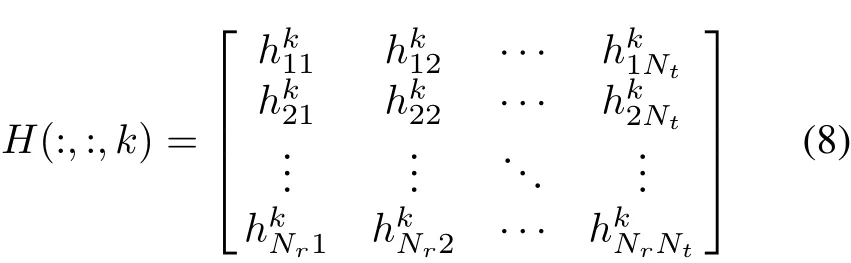
Then the tensorHis transformed to a matrixH(1)by mode-1 matricization[20]and it can be denoted as

The received signal can be expressed as

where the vectorNis the AWGN.
Letlkexpress the estimation output vector of thekth UE signal,the channel estimation value of thekth UE is denoted by

The UE1 signal should be decoded first with the MMSE process as follows:

And then,the signal UE1 denoted byshould be reconstructed and it will be subtracted from the received signal.
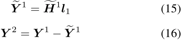
For UE2,the decoding signal is
By following this procedure,the detection for UEKcan be shown as
From(13),(17)and(20),it can be seen that the final classification result can be expressed in the form

whereYkis a constant matrix,bkis a constant vector,andfi(·)represents some form of the nonlinear function.
Obviously,the DL approach can be capable of replacing the traditional SIC method in the uplink MIMO-NOMA system and is even more powerful because it can search for the optimal solution in the way of data-driven.
3.2DenseNOMA
Instead of designing a complex receiver for NOMA transmission,we propose a novel DenseNOMA system to detect the uplink NOMA signal.The construction of the DenseNOMA system can be seen in Fig.3.

Fig.3 Design of the DenseNOMA system
The proposed system consists of three blocks.The first block is the training block.Original UE signals will be produced in this module and specific power should be allocated to UEs.Each UE signal will reach the BS through independent MIMO channels separately.Meanwhile,all the UE labels are also sent to CNN for the training process.The second block is the testing block.The main function of this block is to produce the original UE information as well.The difference is that the purpose of UE signals is used for real-time NOMA detection testing and labels are not provided to CNN as input.To prevent the perfect match between the training and the testing sets,the channel models and generated data in training and testing blocks are independent and identically distributed(i.i.d.)so that the CNN performs with a smaller difference between the training and the testing process.The third block is the CNN detecting block.All the processes including channel estimation,digital down conversion,decoding, filtering and decision are replaced by the unified CNN detecting.The details are discussed in the next subsection.
Overall, two steps should be taken in the workflow of the DenseNOMA system.In Step 1,the training block starts to work.It is connected to the CNN block while the testing block remains unconnected.The original UE signals and labels are provided to CNN for training in the way of supervised learning.In Step 2,the testing block is activated while the training block remains suspended.The real-time testing is carried out by CNN.System performance will be evaluated.Relevant parameters and results are presented in Section 4.
3.3 CNN design
Inspired by the DenseNet[21],we propose a novel DenseNOMA system for uplink NOMA detecting.The system can process the received signal directly.Considering the digitized received signal with the carrier contains a mass of sampling sequences,classical DNN is hard to handle the situation.The proposed system can reduce sharply the computational complexity by the convolutional and pooling operation, and the dense structure can improve the information transmission efficiency.
The input data is a 3-D matrix including antenna dimension,time dimension and data real/image dimension.Before the signal is sent to the DenseNOMA,a color preprocessing where data is normalized in the three dimensions separately should be finished to speed up the convergence in the training step.
The DenseNOMA system is designed for the characteristics of uplink NOMA signals.Its architectures can be seen in Table 1.Nine layers including one convolution layer,four dense blocks,three transition layers and one classification layer constitute the system.Input data is delivered to the first 4×7 convolution layer for elementary feature extraction.The next is four continuous dense blocks among which three transition layers are embedded into every two dense blocks.It is the main body of the DenseNOMA to process and decode the NOMA signal.The last layer is a fully connected layer to realize the classification process.

Table 1 Architectures of DenseNOMA
Notably,the first dimension of the input stands for the received antenna.The information of all antennas should be used simultaneously throughout the whole process.Thus,the size of the antenna dimension is designed to remain unchanged until the last layer.Moreover,the initial size of the sampling in one symbol is 50,and it should be padded to 56 before it is sent to the DenseNOMA because of the proper size for the following layers’output size.The size of the convolution kernel and stride is designed empirically after a large amount of test data.
The dense block consists of several bottleneck layers.The output of the bottleneck layers will be concatenated to the previous feature map as the input of the next layer.This structure of dense connectivity can improve the information flow between layers rather than by increasing the layer of CNN.It means that fewer parameters are needed to optimize the networks and the final classification can be executed based on all the mappings in the networks.A dense block with two bottleneck layers can be seen in Fig.4(a).Fig.4(b)shows the specific process of the bottleneck layer.This layer can be divided into two parts.The first part can be defined as a function including four operations:normalization,Relu,convolution and drop out.The kernel of convolution is 1×1.The second part is exactly the same as the first part except that the kernel of convolution is changed to 3×3.The bottle structure can obtain better representation of the input with reduced dimensionality to improve the computation efficiency.Fig.4(c)shows the transition layer.As can be seen,it contains a batch normalization,a Relu function,a 1×1 convolution,a drop out layer and an average pool.This layer is used for connecting two dense blocks.The convolution layer and the average pool can halve the data and feature maps.

Fig.4 Structure of dense block
After finishing the feature extraction by all the dense blocks,the data is sent to a classification layer to accomplish the data classification.A 4×4 average pool reduces further the data dimension to 288 neurons.Benefiting from the strong learning ability in previous layers,the last fully connected layer with the sigmoid function can realize the final signal recovery with a few shallow layers.
Considering that all the UE signals should be decoded at the BS simultaneously,the output structure can be designed to form groups which can be seen in Fig.5.For a four antennas quadrature phase shift keying(QPSK)signal at the receiver,there are four groups and 16 neurons at the output layer after one-hot coding.In the form of softdecision, each group outputs its UE signals with the grouping sigmoid function.

Fig.5 Design of the output layer
4.Simulation
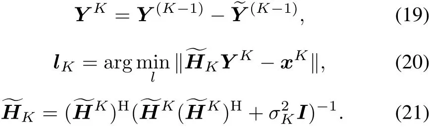
The proposed system works under the Windows 10 operating system.Numeral experiments of training and testing blocks are carried out with the simulation software Matlab.The CNN detecting block is completed with Python 3.6 and the DL framework TensorFlow with the GPU acceleration is employed to realize the DenseNOMA detecting algorithm.Suppose there are two UEs in one cluster.Each UE has only one antenna while BS has four.The MIMO channels with Rayleigh fading and the AWGN channels are considered in our simulation.The total power of the received signal is normalized to 1 W,and the signal from UE1 is supposed to be allocated with 80% of the power and UE2 20%.QPSK is adopted as the modulation scheme.Input data of the DenseNOMA receiver is the digital signal with the carrier and the number of sample points per symbol is 50.All the key parameter settings can be seen in Table 2.
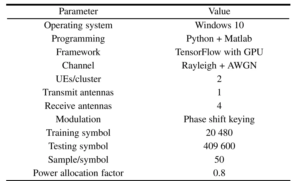
Table 2 Parameter settings in the simulation
The DL optimization algorithm is used for searching for the optimal hyper parameters efficiently.Here,we use the Adam algorithm for its rapid convergence of the network.Cross-entropyH(P,Q)can measure the difference between two distributions from the view of information theory,and it is considered as the loss function which can be expressed as
The regularization methods can be used to avoid the problem of network over fitting by adding the specific term to the loss function.Here,the L2 regularizationis used.The detail of DenseNOMA can be depicted in Algorithm 1.
Algorithm 1DenseNOMA detecting
Step 1Initialize the CNN model.
Step 2Generate training and testing data.The data can be expressed as a 3-D form(antenna×sample/symbol×real/imaginary).
Step 3Set the key parameters,including convolutional kernel,pooling size,stride,mini-batch,learning rate,and output function.
Step 4Execute the forward transmission process and acquire the final output
Step 5Calculate the loss function Loss(y,y):

Step 6Calculate and update the parameters with the Adam optimization algorithm[22].
Step7If the loss function cannot meet the requirement,return to Step 4 for retraining,otherwise go to next step.
Step 8Test the trained DenseNOMA system.The symbol error rate(SER)-signal to noise ratio(SNR)curve is provided.
Fig.6 shows the SER of the DenseNOMA system compared with the SIC method.
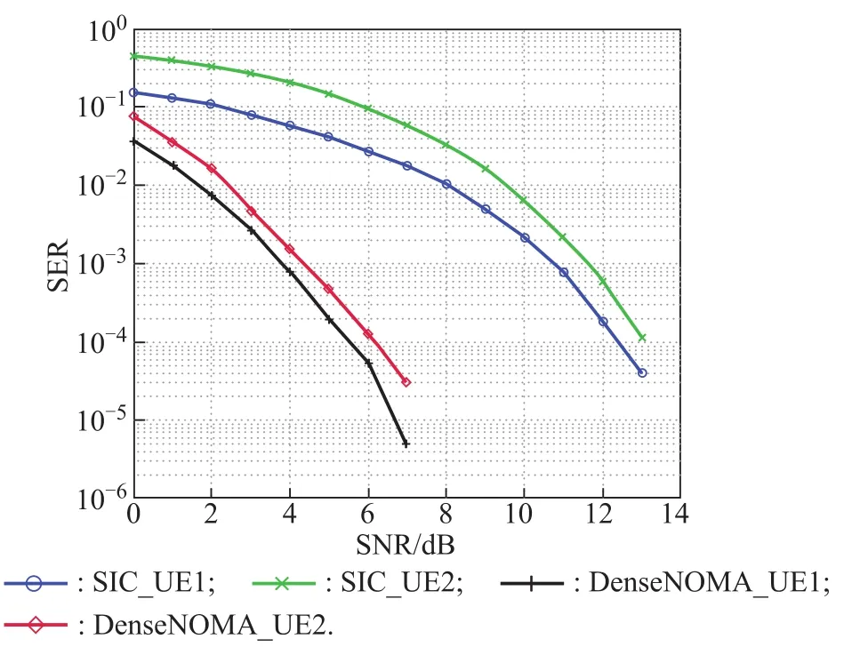
Fig.6 SER of NOMA-SIC and DenseNOMA with QPSK
The signal is modulated with QPSK.The channel state information(CSI)is supposed to be known at the receiver with SIC while it is unknown with the DenseNOMA system.Obviously,the DenseNOMA detecting has a better performance.At the 10−4level,SER values of the proposed DL method reach 5.7 dB and 6 dB for UE1 and UE2 respectively,while those of the SIC method are 12.1 dB and 12.5 dB respectively.The performance improvement reaches approximately6.5 dB with the data-driven approach.
We also provide the simulation of detection performance with different modulations.Fig.7 shows the first scheme:the BPSK modulation for both UE1 and UE2.It can be seen that the SER curve with DenseNOMA of UE1 is nearly coincided with that of UE2.Both UEs reach 1 dB while those with the SIC method reach 9 dB and 11 dB at the 10−4level.The excellent improvement not only results from the greater noise margin of BPSK,but also from the powerful ability to search for the optimal solution of the DenseNOMA system. Meanwhile, it can be proved that the error propagation problem of SIC can be eliminated with the DL method.

Fig.7 SER curve of NOMA-SIC and DenseNOMA with BPSK
Fig.8 depicts the second scheme:BPSK for UE1 and QPSK for UE2.To balance the throughout and performance of NOMA transmission,the power allocation factor is changed to 0.7.From the SER-SNR curve,we can see that the DenseNOMA system brings 4.8 dB and 6.7 dB gains for UE1 and UE2 respectively.
Fig. 9 shows the impact of the mini-batch size on the loss function.Restricted by the computer memory,we compare three different mini-batch sizes.It can be seen that size 320 can converge faster than others for its larger data size per iteration.The convergence speed of the loss function decreases gradually with the decrease of the mini-batch size.The minimum size 32 has the lowest convergence speed and the curve has been in a significant fluctuation.In the simulation,there is a small difference of time we take to train the DenseNOMA per iteration between these minibatch sizes.Thus,we recommend using larger mini-batch sizes to reach faster convergence speed.
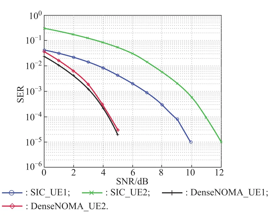
Fig.8 SER curve of NOMA-SIC and DenseNOMA with B/QPSK

Fig.9 Impact of mini-batch on the loss function
In addition,the SIC computational complexity can be expressed asO(L)whereLstands for the number of UEs in one cluster.For the well-trained DenseNOMA system,however,its computational complexity isO(1)with limited multiplication and addition operations.It means that,it can be realized to detect the NOMA signal in real time.
5.Conclusions
In this paper,we design a DenseNOMA system to detect the uplink NOMA signal.The proposed DL method can handle the NOMA signal with the carrier directly without any traditional signal processing.The optimal signal processing and detecting can be finished by the DL approach intelligently without the complex modularity receiver design.Numeral results show the powerful SER performance compared with the SIC.We can obtain up to 6.5 dB gain in our simulation.The problem of error propagates of SIC
can be restrained to some extent with the DL method. In order to further improve the throughout and accuracy of the NOMA transmission,learning-based power allocation and real time channel estimation with low computation complexity can be considered as a topic for future research.Besides,exploring the LSTM network to deal with the effect of memory channels is important in many practical scenarios.Signal transmission with unsupervised learning is also an interesting direction to study.
杂志排行

Journal of Systems Engineering and Electronics的其它文章
- Multi-target tracking algorithm based on PHD filte against multi-range-false-target jamming
- Design,analysis and optimization of random access inter-satellite ranging system
- Parity recognition of blade number and manoeuvre intention classificatio algorithm of rotor target based on micro-Doppler features using CNN
- A transceiver frequency conversion module based on 3D micropackaging technology
- Renormalization:single-photon processes of two-level system in free space
- Adaptive resource management for multi-target tracking in co-located MIMO radar based on time-space joint allocation