Path Planning and Navigation of Oceanic Autonomous Sailboats and Vessels: A Survey
2020-09-28JINGWeiLIUChaoLITingRAHMANMohaimenurXIANLintaoWANGXiWANGYuGUOZhongwenBRENDAGumedeandTENDAIWachiKelvin
JING Wei, LIU Chao, LI Ting, RAHMAN A B M Mohaimenur, XIAN Lintao, WANG Xi, WANG Yu, GUO Zhongwen,BRENDA Gumede, and TENDAI Wachi Kelvin
Path Planning and Navigation of Oceanic Autonomous Sailboats and Vessels: A Survey
JING Wei1), 3), LIU Chao2), *, LI Ting3), RAHMAN A B M Mohaimenur3), XIAN Lintao2), WANG Xi2), WANG Yu4), GUO Zhongwen2),BRENDA Gumede2), and TENDAI Wachi Kelvin2)
1)Department of Computer Fundamentals, Ocean University of China, Qingdao 266100, China 2) College of Information Science and Engineering, Ocean University of China, Qingdao 266100, China 3) Department of Computer Science,University of North Carolina at Charlotte, Charlotte, NC 28233, USA 4) Department of Computer and Information Sciences, Temple University, Philadelphia, Pennsylvania 19122, USA
Oceanic autonomous surface vehicles (ASVs) are one kind of autonomous marine robots that haveadvantages of energy saving and is flexible to use. Nowadays, ASVs are playing an important role in marine science, maritime industry, and national defense. It could improve the efficiency of oceanic data collection, ensure marine transportation safety, and protect national security. One of the core challenges for ASVs is how to plan a safe navigation autonomously under the complicated ocean environment. Based on the type of marine vehicles, ASVs could be divided into two categories: autonomous sailboats and autonomous vessels. In this article, we review the challenges and related solutions of ASVs’ autonomous navigation, including modeling analysis, path planning and implementation. Finally, we make a summary of all of those in four tables and discuss about the future research directions.
autonomous sailboats; autonomous vessels; model analysis; path planning
1 Introduction
Autonomous surface vehicles (ASVs), also called unmanned surface vehicles (USVs), are developing rapidly and becoming an important research field in marine science and technology, and a great significance to marine industry as well (Bertram, 2008; Manley, 2008). Compared with traditional marine vehicles or vessels, ASVs could perform some special tasks independently. Besides, they become a fashionable manner with low energy consumption (Liu., 2016), especially in the long-run missions. The applications (Steimle and Hall, 2006; Mahacek., 2008; Campbell., 2012; Wang., 2012; Sarda., 2015) of ASVs include not only those in the civilian world but also in many sciences and national defense fields, such as data collection for ocean environment, marine monitoring, hostile facilities detection and underwater communications.
Generally, there are two different kinds of ASVs:and(Cruz and Alves, 2008). Fig.1 shows the examples. Autonomous vessels have got enough attention in the research field due to the following reasons. Firstly, autonomous vessels have propulsion systems to provide thrust from the powerful propellers instead of the uncontrollable wind. Secondly, the vessels have a flexible range of turning direction and greater velocity than sailboats, which make autonomous vessels more efficient and attractive. Finally, autonomous vessels have practical and valuable usages in various marine vehicles, such as battleships, cargo boats, merchant ships, passenger boats and yachts.
Autonomous sailboats are more complicated than vessels because sailboats have more external factors to be considered. Even though the path planning and collision avoidance of sailboats are similar to those for vessels, sailboats can only use the power from the sail instead of the steady power from propellers. Unpredictable winds, ocean waves and currents are the main factors that affect the velocity and direction of sailboats,, the unpredictable ocean environment drives autonomous sailboats and affects their operations. Although there are lots of factors of autonomous sailboats movement, wind is the only power to keep them sailing. This is a great feature since fossil fuels are no longer a necessity for autonomous sailboats. It consumes less energy and is more environment friendly compared with autonomous vessels. Low-power dissipation and long-run work cyclic characteristics make autonomous sailboats have the ability to complete some special tasks independently, such as some long-run and uninterrupted ocean missions. Table 1 shows the differences between autonomous vessels and autonomous sailboats.
Overall, the most challenging problem of autonomous sailboats is how to accomplish the sailing from the starting point to the destination effectively under the circumstancesof changing winds and ocean waves. As for autonomous vessels, usually with larger size or more expensive value, there is no doubt that the safety issue is the most crucial issue. It is important to solve the path planning problem of how to avoid the collision and ensure the safety while sailing with the most practical method.
This survey presents the recent research of path planning and navigation in ASVs. Specifically, we discuss and divide the existing methods into two categories: autonomous vessels (Section 2) and autonomous sailboats (Section 3). For each category, we focus on model analysis, methods of path planning and collision avoidance, and implementation. In Section 4, we summarize these methods within four tables for better comparison. We also point out the deficiencies of the existing works and discuss the future research directions.
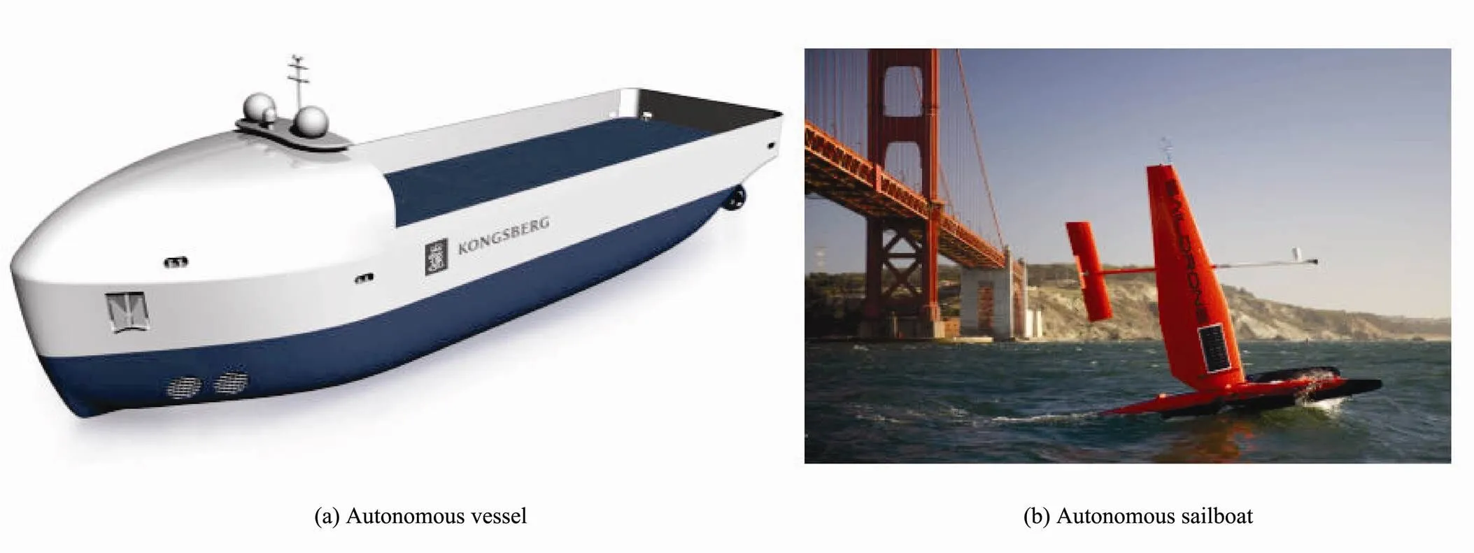
Fig.1 Examples of an autonomous vessel from KONGSBERG (Kon) and autonomous sailboat from SailDrone (Sai).

Table 1 Autonomous vessels vs autonomous sailboats
2 Path Planning for Autonomous Vessels
Comparing with autonomous sailboats, autonomous vessels are more stable and practical. The powerful propellers provide sufficient motivation for the vessels regardless of the unstable wind. Although autonomous vessels have higher security, according to the safety restrictions rules defined by the International Maritime Organization (IMO) (MSC, 2007) and the Convention on the International Regulations for Preventing Collisions at Sea (COLREGS) (Commandant, 1999), certain specific sailing movements should be forbidden or rerouted. To explore the navigation safety, several works (Lee., 2004; Kuwata., 2014) have been done under COLREGS. Even so, the technology of autonomous vessels is valuable in the modern navigation. There is no doubt that the research of autonomous vessels navigation is still a popular subject.
2.1 Model Analysis
The Maneuvering Modeling Group (MMG) model (Yasukawa and Yoshimura, 2015) is widely used in building mathematical model of vessels motion. It was originally proposed by the Maneuvering Modeling Group (MMG) (Ogawa., 1977) in Japanese Towing Tank Conference. MMG model and its variations can be used for modeling and simulating ship motion in many studies and applications (especially for navigation safety). For example, Fang. (2018) used the MMG model to simulate the ship’s motion and design a decision-making system that built a simplified simulation model for the safety of ship navigation. All decisions follow the COLREGS rules to achieve the collision avoidance. To simplify the model, the authors assume that the environmental factors, such as the wind and waves, has no effect on the motion simulation of the ship.
Similarly, Fan. (2018) also employed the MMG model to study their mathematical model of, a vessel with pod-like propulsion (more details aboutwill be provided in Section 2.4). Three degrees of freedoms were used to represent the planar motion model. After the derivation and simplification, their system can be simplified to a first-order system, which confirms there is no difference betweenand the ordinary propeller-rudder propulsion ship. Multiple field experiments were tested to identify and verify the proposed model and analysis (Lee., 2004; Kuwata., 2014).
2.2 Path Planning and Navigation
Although the thrust of autonomous vessels is powered by the propellers, which is relatively stable, the velocity of vessels would reduce due to the resistance from the sea. So, the critical factor that should be considered in path planning is the sea state. The existing methods for path planning mainly have three categories, advanced equipment based to identify the environment (Huntsberger., 2011; Kuwata., 2014), graph search based methods, and machine learning based methods. In this section, we only focus on the last two categories.
1) Graph-Search Based Methods
Graph-Search algorithm has been used as the routing method of ASVs, where a graph is built for navigation. A graph is a discretization of space, where the nodes represent the starting point, the end points and all the potential places that the vessel can reach. The links, or edges, indicate the possibility for a material point moving on the graph to travel from one node to the others. Generally, the graph with nodes on a regular grid in latitude and longitude coordinates with the resolution of 45˚ or 60˚,which determines the density of the potential route. However, Mannarini. (2013) used the grid with the angular resolution 26.6˚, which is arctan (1/2). Because they deemed that an increase in angular resolution is computationally more effective than an increase in grid resolution. The weight of edge is the time needed for traversing the edge, and the distance between two connected nodes is specified number of nautical miles or calculated by the Euclidean distance. The final goal of the path planning algorithm is to find a path which has the lowest cost,, minimum travel time. Fig.2 shows an example grid with the resolution 26.6˚. From the figure we can see that each node has 4 distinct directions in each quadrant (except in northwestern quadrant) and 6 connected edges (in northeastern quadrant). All the nodes could be the next destination. The edges in northwestern quadrant are removed because of the barriers in the area.

Fig.2 The sample of a grid with the angular resolution 26.6˚.
More than the grid or graph method, the wave height, wave direction and wave period can be taken into consideration, such as in Mannarini. (2013). The speed of the vessel reduces due to the oceanographic conditions. In Mannarini. (2013), the oceanographic conditions include the effect of wave height and wave direction. According to the recommendations of the IMO, surf-rid- ing and parametric rolling motion should be avoided, which are two dangerous situations that can cause the vessels to capsize. Surf-riding means that the vessels are sailing in the same direction with wave. The parametric rolling motion means that the frequency of the ship when rolling satisfies the specified conditions with the encountered wave frequency. Hence, in graph-search based methods, the potential edges directed to the dangerous situations should be removed before implementing the routing algorithm, such as Dijkstra algorithm.
2) Reinforcement Learning
While graph-based methods can usually find the optimal path, they rely on graph’s global information. However, in reality, it is hard to obtain the global graph or the graph is dynamic. Therefore, learning techniques have been used to self learn optimal path based on local and available information. Yoo and Kim (2016) applied the reinforcement learning (Sutton and Barto, 1998, 2018) to select the optimal path. Flow diagram of reinforcement learning is shown in Fig.3. The state sis the current position state and heading state of the vessel. The position state is discretized into square regions by the tile coding technique. The heading state of the vessel does not change within a currently located tile. A new action is selected only when the vessel reaches the boundary of the adjacent tiles. There are three actions which include going straight, turning right, or turning left. The environment represents the direction and the velocity of the ocean currents, and reward r1is provided to the vessel agent after actions is took. The negative reward here indicates the amount of time the agent remained in each tile. At the same time, the new state of vessel is updated ass1. Q-learning method is used to determine a sequence of actions, which generated the minimum-time path between two given points.
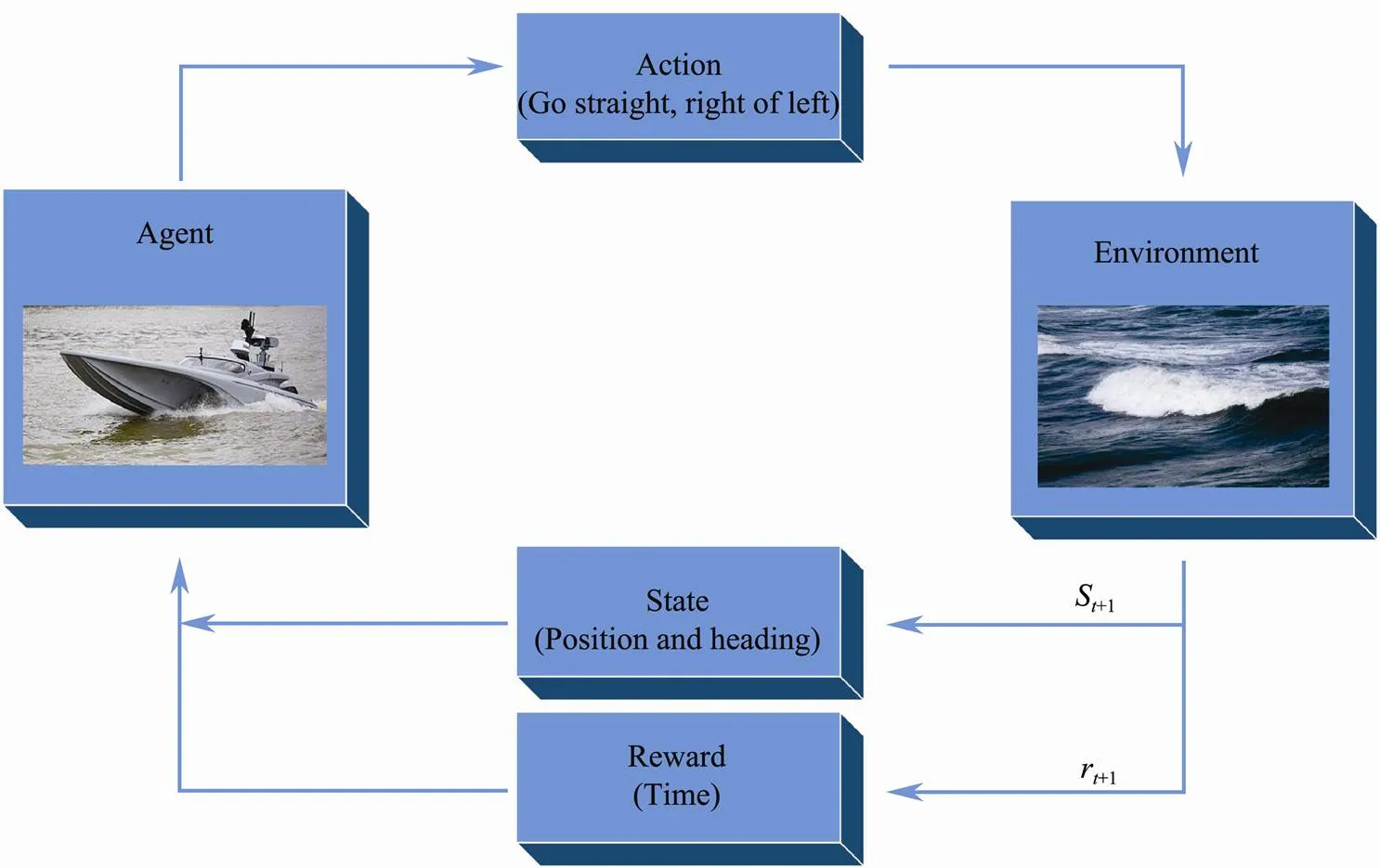
Fig.3 Flow diagram of common reinforcement learning method.
2.3 Collision Avoidance
Collision avoidance is a very important mission of autonomous vessels. Note that it is not enough for the vessel to just sail from the start to its destination, how to make sure of the safety of its navigation by avoiding the collision is also the critical problem. The goal of collision avoidance is usually at a higher level of path planning. The collision of vessels happens not only between the stationary obstacles such as the land mass or the islands, but also between the ships. Therefore, there are many proposed methods (Polvara., 2018) focusing on solving this challenge, such as fuzzy logic based methods (Kao., 2007; Perera., 2011) and ant colony optimization (ACO) based methods (Lazarowska, 2015). In this section, we present three example methods, Automatic Identification System (AIS) data based method used in cargo ships, yacht and large-scale ships,and its improved algorithm (based on reinforcement learning to deal with both sea wind and currents) and.
1) AIS Data based Methods
In recent years, Automatic Identification System (AIS) can share information between the nearby ships and provide the operation of encountered ships in a real-time way. For example, the current vessel can obtain the position, the speed and the direction and encountered ships from the AIS. Such information can be used for collision avoidance. Fig.4 illustrates the relative motion between two encountered ships. The two main parameters are distance of the closest point of approaching (DCPA) and time to the closest point of approaching (TCPA), which are defined as follows.

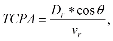
Where

Here, Dris the relative distance from the own ship to the target ship, vr is the relative motion velocity, φris the angle of the relative velocity, φt is the azimuth of the target ship and ∆C is the crossing angle of two ships. The positive and negative values of the DCPA are decided by the location of the target ship and whether the target ship can pass the bow of the own ship. If TCPA is positive, there is a collision risk. Otherwise, there is no such risk.
Chen(2015) used the AIS data as the sources of information in their ship collision avoidance system. Five kinds of encounter situations (with different ∆) were considered, and the fuzzy membership degree was applied to construct a fuzzy collision risk evaluation model. The DCPA, TCPA, the relative distanceD, the azimuth from the own ship to the target shipβand the speed ratio (v/v) were selected as the factors to calculate the collision risk index (CRI). Based on the CRI and threshold range, different collision risk levels will be displayed with different colors in the designed embedded system.
Along the line of Chen(2015), Xu(2016) further simplified the encounter status of ships into three situations: head-on, crossing and overtaking. In addition, they presented the smooth and changing continuous ship domain of the own ship and provided the degree of course alteration that the boat should change to realize collision avoidance.
AIS data can also be used in maritime anomaly detection. Zhen(2017) used the data to calculate the spatial and directional distance with the different weight between vessel trajectories. Then, hierarchical and-me- doids clustering methods were applied to process the vessel trajectories. The optimal number of clusters and the combination of spatial and directional distance could be obtained after the evaluation process using Variance Criterion Ratio method. Finally, a Naïve Bayes classifier was applied to classify and detected the anomalous vessel trajectory.
2) Heading Window Methods


whereis the angle of the center ofth obstacle andφis the tangent angle ofth obstacle. Besides, there are two more considerations. First, the rotational velocity is more important than translational velocity because tuning the heading angle is the way to avoid collision. Second, the relative coordinate should be transferred to the absolute coordinate. Overall, it is a mathematical optimization pro- blem where the best avoidance heading angle can be derived.
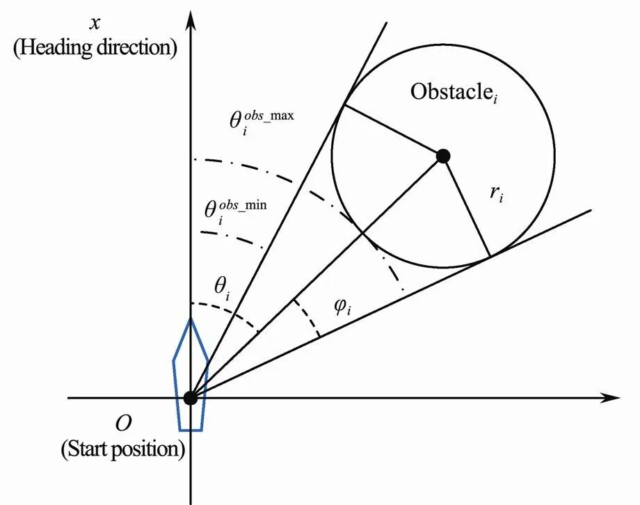
Fig.5 An illustration of obstacle constraint analysis by tangent method in Tang et al. (2012).
Zhang(2014) further improved the idea of OAA- BHW and implemented the Local Obstacle Avoidance Module. By considering the interference of the wind and sea currents, the heading and course angles were modified. The result of LOAM cannot be directly used in the basic motion control module (BMCM). Therefore, considering the complicated external disturbance, the Adaptive Learning Module (ALM) was introduced to deal with it. The core of ALM is Sarsa on-policy reinforcement learning algorithm which is used to search for an optimal course compensation angle to offset the course deviation.
3) Evolutionary Algorithms
Szlapczynski (2011) proposed a method called evolutionary sets of safe ship trajectories, for solving the problem of multiple ships encountering situations on open waters (no obstacles domain model) or restricted waters (with stationary constraints domain model). For the restricted waters, there are four kinds of random mutation operators (Fig.6) used to increase the fitness value of the trajectory, and five kinds of specialized operators (Fig.7) used to avoid collisions with other ships or stationary obstacles. In these figures, the dotted black line indicates the original trace and the blue line is the trace after operations. As shown in Fig.7, segment insertion happens when there is enough time for three course alterations. Node insertion happens when there is not enough time for a whole new segment, but enough time for two course alterations. Compared with node insertion, first node shift happens when the collision point is close to the first node of the segment. And if the collision point is close to the second point, the second node shift happens. The last operator segment shift happens when there is not enough time for the node insertion and the collision point is close to the middle of the segment. At last, the result of operations is evaluated by a fitness function. In Szlapczynski (2013), Szlapczynski (2015), the author further extends his method to compliance with standard Rule 10 and Rule 19 of the COLREGS respectively by adjusting the fitness function.

Fig.6 Four random mutation operators in Szlapczynski (2011). Here, the dotted black line is the original trace, while the blue solid line is the new trace after operations.
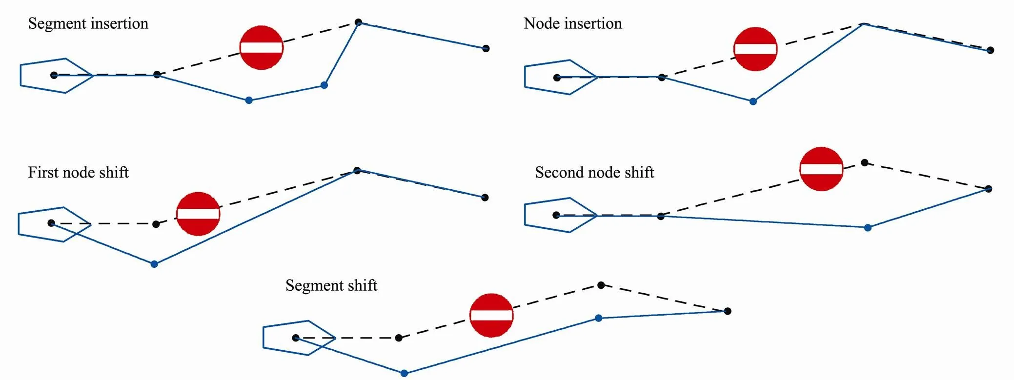
Fig.7 Five specialized operators for collision avoidance in Szlapczynski (2011).
2.4 Implementation of Autonomous Vessels
There are many autonomous vessels in use all around the world (Alves.,2006; Naeem.,2009; Huntsberger.,2011). A number of autonomous vessels are used in research and operated by research institutions and universities, because these autonomous vessels have the advantages of being small size, low cost, more flexible and accessible.
Gadre. (2012) studied on path planning of backward motion in a narrow and strange riverine by using Virginia Tech riverine unmanned surface vehicle, which is a rigid hull inflatable boat with a servo-actuated outboard motor. The system uses the receding horizon approach and solves an optimal control problem. The forward nonlinear backstepping control law is modified to apply in sternward motion.
andare two autonomous vessels of the Dalian Maritime University, China, which have been used as experiment targets for several research projects. Zhang and Zhang (2016) have usedto carry out several simulation experiments for their proposed nonlinear feedback strategy to reduce the control error. Based on, Li(2016) have proposed an adaptive RBF neural network method for its course control. The proposed adaptive RBF neural network can compensate modeling errors and disturbances. Under the condition that the autonomous vessel is affected by many external interference factors, it makes the autonomous vessel have nonlinear, uncertainty and time-varying characteristics in the real environment. The results of simulation based onprove that the proposed control scheme had a more robust and better performance compared with traditional PD controller. To further improve the robustness of course control in heavy sea states, Fan(2018) proposed a practical integrated nonlinear feedback course- keeping course control strategy forwith pod-like propulsion. They replaced the standard error with the square of the error and inverse sine function of the error in the feedback control system. A set of field experiments showed that the error parameter of their system is reasonable in real sea environment.
3 Path Planning for Autonomous Sailboats
The power of sailboats comes from natural wind and current, which makes the sailboats become one of the traditional water transportation before the steam engine. Comparing with the other modern water transportation, the greatest advantage of sailboats is still the green power source. In other words, sailboats could save a lot of fossil fuels, which makes sailboats become the best instrument to do long-run cyclic marine work instead of fuel using ships. For path planning and navigation of sailboats, the main feature that should be of priority consideration is wind and current because they are the main power to provide the thrust to the sailboats.
3.1 Model Analysis
Powered by wind and current and effected by the complex external conditions, establishing a mathematical model for sailboats is important. The six degree-of-free- dom (DOF) motion model is usually used in all kinds of vessels’ simulations. Fig.8 shows the six-DOF motion model of a sailboat. Surge, heave and sway motions belong to translational motion, while yaw, pitch and roll motions belong to rotational motion. In general, researchers only consider three degrees (Elkaim and Kelbley, 2006; Cruz and Alves, 2010) or four degrees (Xiao and Jouffroy, 2014) of sailboats for simplification.
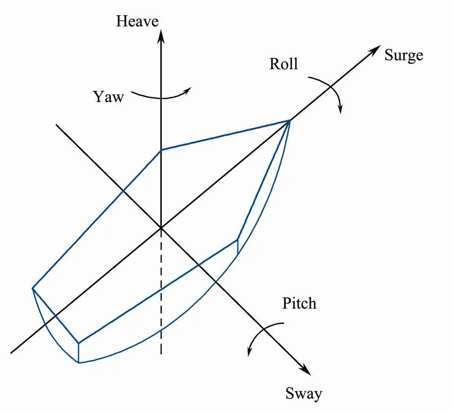
Fig.8 Six degree-of-freedom motion model of a sailboat.
When the wind blows across the sail, two sides of the sail receives different velocities of wind. Based on Bernoulli effect (Murphy, 1986), the difference of wind velocities causes the different pressure, which generates the lift force on the sail. We can separate the wind into three kinds, the true (read) wind, the navigation wind and the relative wind. The true wind is the wind speed tested on the mainland. The navigation wind is the opposite of sailboat’s direction and equal to sailing speed. The relative wind is the resultant of the true wind and the navigation wind. The force analysis of sailboat is shown in Fig.9. The angle between relative wind and sailing direction is. The result of relative wind generates the force of liftFwhose direction is perpendicular to relative wind. And the force of dragFwhose direction is the same as relative wind. At the same time, the water makes two component forcesFandFto the sailboat because of hydrodynamics. The resultant force of thrust makes the sailboat go straight. And the forces of lateral on the sail and boat’s keel create the leeway angle. According to the force analysis, the speed of the sailboat is related to the speed of the wind, and the sailboats are impossible to sailing straight in the direction of upwind. In order to successfully reach the destination in the direction of upwind, sailboats have to take a zigzag route.
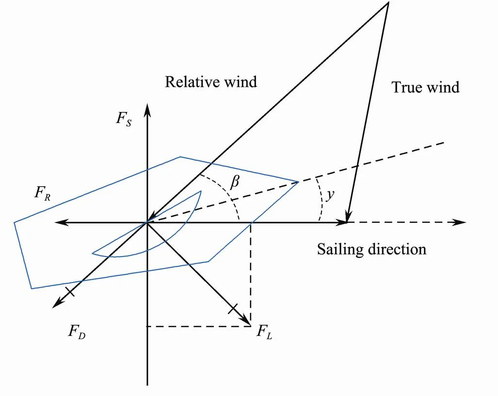
Fig.9 Force analysis of a sailboat.
Xiao and Jouffroy (2014) analyzed the model of sailing yacht with four-degree-of-freedom which included surge, sway, yaw and roll motion. They excluded the heaving and pitching motions. Besides the propulsive power provided by the winds, two more features of sailboat were considered. The first feature is the behavior of the sail as it changes sides while tacking or jibing. The second feature is the internal moving mass which usually happens on the smaller sailboats. This feature also make it act as the rudder,.., rudderless sailboat. Based on the dynamic model studying, they achieved the course control by tuning method. In tuning method, five parameters are used and obtained by computing the equilibrium points of the system. The controller system provides control action to minimize the error in heading by tuning these parameters. The other assumption of their work is that the velocity of the water is zero, meaning they neglect the influence of the waves and currents.
You(2017) also focused on the motion model of sailboats and have established an MMG three-degree-of- freedom motion model. Recall that MMG motion model is widely used in vessel modelling. Vessels, oar and rudder are usually separated parts to be considered for force analysis. For sailboats, the wind power takes place of the force of propeller. Hence MMG model for modeling sailboats uses three different parameters: longitudinal, lateral and vertical of the ship, which refers to the roll motion, the pitch motion and the yaw motion. They are all taken into consideration as well as the influence of the wave and current.
Another numerical model for sailboats is Velocity Prediction Programs (VPP) (Kerwin, 1978). In VPP, many dynamical aspects are parameterized, the output of VPP consists of hydromechanics and aerodynamic force table of the sailboats, and the polar plot demonstrates the sustained sailboat speed and point of sail for various values of wind intensity (de Jong.,2008). In de Jong(2008), the particular setup of the VPP for traditional Dutch sailboat of the type sketsjes is provided. Fig.10 shows an example of polar plot from the output of VPP with the real data of ship J24 (J24.b). The data is available at (J24.a).
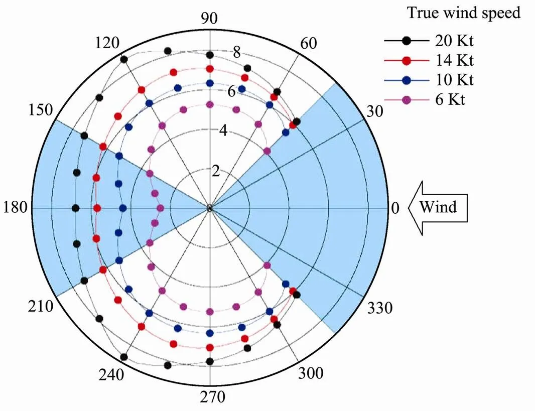
Fig.10 The relation between wind-speed and boat-speed for a given true wind angle.
3.2 Path Planning and Navigation
Path planning is the main purpose and fundamental capability of autonomous sailboats. Since it is incredibly difficult to consider all the internal and external influences in the real environment, researchers usually only concentrate on the winds for path planning. Here, we briefly discuss three major path planning methods used in the autonomous sailboats: graph-search based methods, potential field based methods and classical sailing methods.
1) Graph-Search based Methods
Graph-search based algorithms can still be used for autonomous sailboats. Different from the vessels, we can get the velocity of the sailboat from the polar diagram (as shown in Fig.10), which is depending on the type of the sailboats, true wind angle (TWA), and true wind speed (TWS). Fig.10 shows that there is no curve from 315˚ to 45˚, which means that the sailboats cannot go straight in the upwind direction. Then a routing graph can be defined on the grid for sailboats, as shown in Figs.11(a) and (b). The arrow represents the direction of the wind at the node. Nodes located on a land mass or obstacles are not displayed in the graph (as in Fig.11(a)).
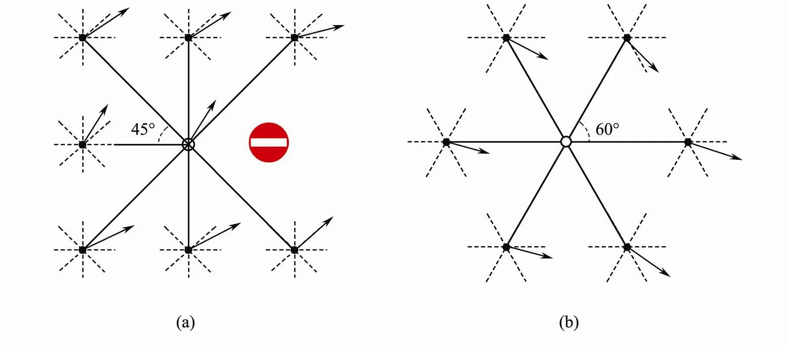
Fig.11 A part of the routing graph.Here, edges to and from the center node are denoted as solid lines, while edges connecting the surrounding nodes are denoted as dashed lines.
In Langbein(2011), each node is connected to its eight nearest neighbors. Each node is explained with the winds vectors, shown as bold arrows in the Fig.11(a). So not only the nodes located on the land mass, but also the nodes where wind-speed exceeds the limit are not included. An A*-algorithm is adopted for the routing in which a heuristic is used for performance gain. In other words, the best node xis not the node having the lowest cost(x) but the node having the lowest value of(x)+(x). Here,(x) is the distance from xtoxdivided by the boats hull-speed, which is configurable by the users of the algorithm.
The method by Mannarini(2015) considers edges from each node to its first and second neighbors on the grid,,the angular resolution of about 27˚ (as shown in Fig.2). The Dijkstra algorithm is employed to obtain the globally optimal path over the routing graph. Compared with A*-algorithm, the Dijkstra algorithm does not need to add the heuristics part for choosing the lowest cost node. There are two more constraints considered: 1) the edges intersecting or being tangent to the coastline are preliminarily removed from the graph, and 2) the sail- class-specific draught is taken into full consideration in case of stranding.
2) Potential Field based Methods
Pêtres(2011) adapted a potential field algorithm to realize path planning of the sailboat. The potential field is decomposed into two parts, a local potential field which is relative to the wind direction and a global potential field which is relative to the goal point and the obstacles. The lower the potential field is, the closer to the goal point. Therefore, the goal point is the lowest potential field on the whole map. The high potential field includes (from high to low) the obstacles, the upwind potential (upwind no-go zone) and the downwind potential (downwind no-go zone), hysteresis potential. The high potential field of the sailboat is shown in grey area of Fig.12. The dotted region corresponds to the hysteresis potential fieldP, which prevents the boat to tack or gybe too frequently. The whole process of the navigation can be summarized as: choosing the lowest potential field directionPand avoiding the high potential field directions at the same time. In this work, the local potential only depends on the distance between the sailboat and the goal point. Plumet(2015) then made it more reasonable by replacing the distance with the velocity. In that way, the lowest potential direction represents the fastest direction at the same time.
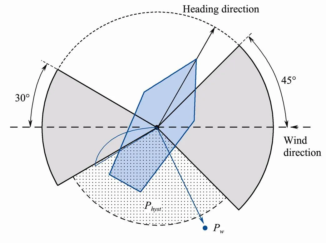
Fig.12 Scheme of the upwind and downwind no-go zone in Pêtres et al. (2011).
3) Classical Sailing Methods
Classical sailing methods concern about the direction of the Velocity-Made-Good (VMG) or Velocity-Made- good-on-Course (VMC). VMG is generally defined as the speed of a sailboat towards or from the direction of the wind,.., speed in the upwind of downwind direction, while VMC is defined as the speed of a yacht relative to the target. They are often used interchangeably. Stelzer and Pröll (2008) considered how to calculate a suitable route for a sailboat to follow the direction of VMC speed. The proposed approach does not need a weather forecast, and only uses the current position of target and boat, the direction of the boat and the true wind. Possible circumstances between the direction of sailboat and wind are discussed, and a hysteresis condition is applied to obtain a unique optimal heading direction. Stelzer(2007) also designed a fuzzy inference system to control the rudder and sails of sailboat to realize the movement such as keeping on the course, sailing through the downwind or upwind. Instead of applying the hysteresis condition, Guo(2011) used a penalty factor to prioritize the new heading direction. Furthermore, they also took into account the obstacle detection base on advanced cameras.
3.3 Implementation of Autonomous Sailboats
To extend and verify the design and theoretical analysis of autonomous sailboats, real implementations of autonomous sailboats have been made (Wrede.,2015; Plumet., 2015; Lam, 2016). Fig.13 shows three examples of autonomous sailboats for research.
Wrede(2015) used the hill-climbing algorithm to optimize the sailing angle, VMG and heel angle for the course control. They used an automated keel yawl sailing boat of the ‘’ type, equipped with all necessary sensors and actuators, as well as a photovoltaic energy system, to perform field experiments of their proposed algorithm.
Pêtres(2012) have also tested their potential field method under realistic conditions with a reduced-scale sailboat equipped with basic sensors and computers. Plumet(2015) proposed a complete hardware and software architecture of their sailboat, and developed all its equipment, including two sensors: an omnidirectional camera and a sonar, which are used for world modeling and obstacle detection.
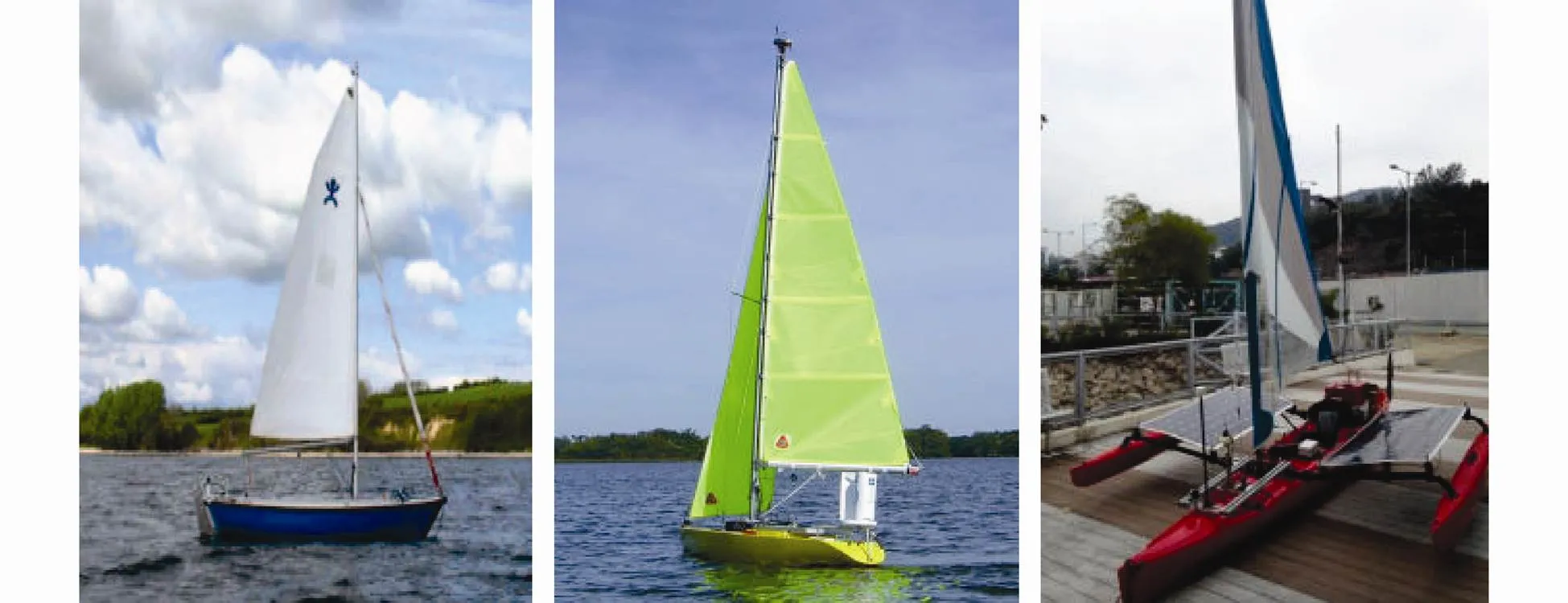
Fig.13 Three real autonomous sailboats used in Wrede et al. (2015), Plumet et al. (2015), Lam et al. (2016).
Lam(2016) have designed an autonomous single passenger trimaran. Sail and rudder control are motorized by three actuators. Two actuators are maneuvered to control the sail extension and retraction rope, and the third actuator is for the rudder control. They designed a tightening mechanism associated with the sail extension rope in case that the lengthy rope jumps out of the pulley. In path selection, the circular region is divided into four parts: right and left effective motion area where the sailboat can go directly, upwind and downwind not-go area where the sailboat should adopt zigzag trajectory.
4 Discussion and Conclusion
This survey considers path planning and navigation methods for both autonomous vessels and autonomous sailboats. For each category of autonomous surface vehicles, we provided detailed reviews on three or four aspects. Tables 2-5 summarize the detail aspects of all reviewed works. Both categories share some common methods while have their own different methods in path planning. The major difference between them is that autonomous sailboats are susceptible to the influences of external factors, so it is harder to realize the navigation of autonomous sailboats. On the other hand, no extra energy but the wind needed makes autonomous sailboats have the capacity to accomplish the long-time tasks where there is inconvenient access to supplies. Autonomous vessels have more application value in the field of civilian.
For the convenience of reflecting the contents of the references, we divide the references into three categories and display them in four tables. Table 2 shows the research target of the references. There is more researches of the vessels than the sailboats. Five considered factors (model analysis, wind, wave, safety restriction and navigation) of the research target are shown in Table 3 and Table 4. At least one factor is studied among the references we mentioned in this paper. In particular, safety restriction means that the researchers have considered the effect of IMO and COLREGS. Then, collision avoidance is merged into path planning in the navigation. Different papers have different ways to demonstrate the result, so the Table 5 shows that how the authors implement their experiments.
There are still some issues for future study in ASV, which include but not limit to:
1) Most of the current research on navigation of sailboats only consider the influence of wind, and usually ignore that the ocean currents also affect the speed and direction of the sailboats. More thorough study of effects from the combination of winds and currents is needed.
2) Many studies investigate the model of vessels and their path planning separately. In path planning, ASVs are usually treated as a point, which is not practical. Therefore, it is more desired to jointly study the vessel model and path planning.
3) With the advancement and maturity of new technologies (such as deep learning and Reinforcement Lear- ning methods that have been used in path planning of indoor robots (Chen., 2017)), we believe learning- based path planning of ASVs becomes a promising direction, which will attract more attentions in the near future.
4) Many demonstrations of algorithm lack the results of field tests. The purpose of studying path planning methods of ASVs is to apply them to the practical marine tasks. So the field tests, as the proven of the methods, are essential in the ASVs’ research.

Table 2 Research target
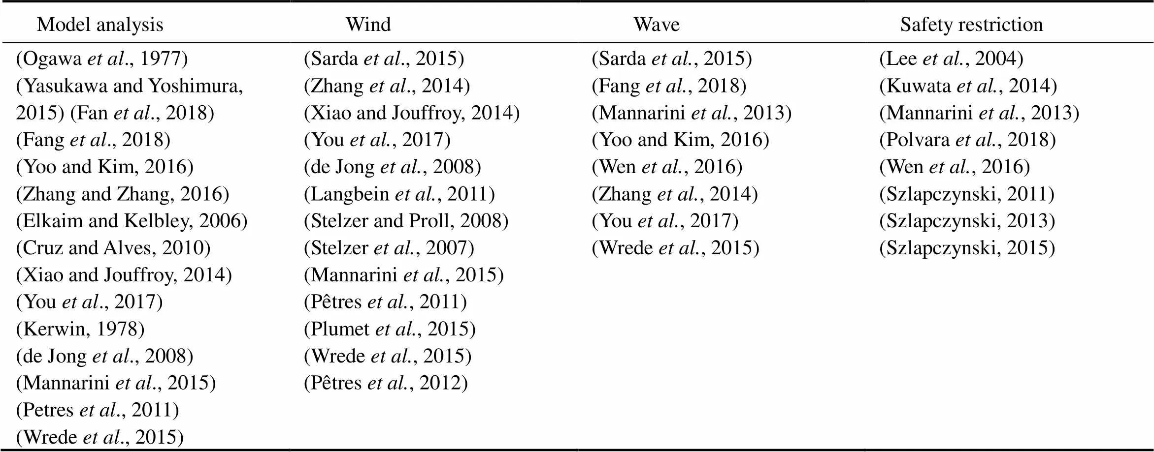
Table 3 Considered factors

Table 4 Navigation
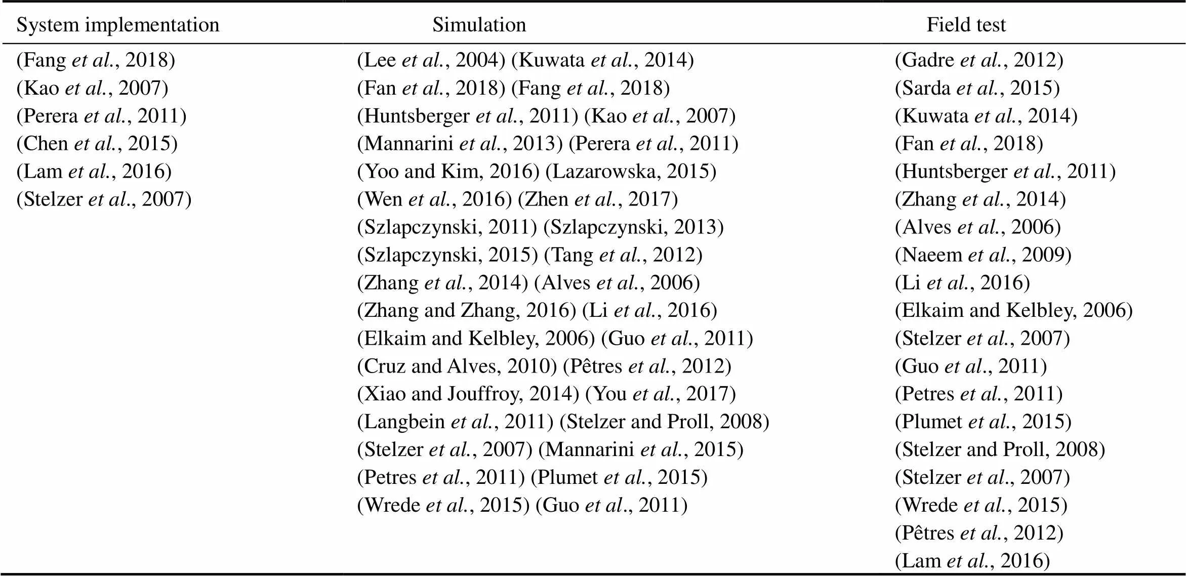
Table 5 Result illustration
Acknowledgements
The study is supported by the work of Chao Liu and Zhongwen Guo, which is partially supported by the National Key R&D Program (No. 2016YFC1401900), the China Postdoctoral Science Foundation (No. 2017M620 293), the Fundamental Research Funds for the Central Universities (No. 201713016), Qingdao National Labor for Marine Science and Technology Open Research Project (No. QNLM2016ORP0405), and the Natural Science Foundation of Shandong (No. ZR2018BF006). The work of Yu Wang is partially supported by the National Natural Science Foundation of China (No. 61572347) and by the U.S. Department of Transportation Center for Advanced Multimodal Mobility Solutions and Education (No. 69A3351747133).
KONGSBERG, https://www.km.kongsberg.com/.
SailDrone, https://www.saildrone.com/
a. J24data, http://76trombones.wordpress.com/offshore-han- dicap-fleet/j24/
b. J24introduction, http://en.wikipedia.org/wiki/J/24.
Alves, J., Oliveira, P., Oliveira, R., Pascoal, A., Rufino, M., Sebastiao, L., and Silvestre, C., 2006. Vehicle and mission control of the DELFIM autonomous surface craft., 1-6.
Bertram, V., 2008. Unmanned surface vehicles-A survey., 1: 1-14.
Campbell, S., Naeem, W., and Irwin, G. W., 2012. A review on improving the autonomy of unmanned surface vehicles through intelligent collision avoidance manoeuvres., 36: 267-283.
Chen, D., Dai, C., Wan, X., and Mou, J., 2015. A research on AIS-based embedded system for ship collision avoidance.IEEE, 512-517.
Chen, Y. F., Everett, M., Liu, M., and How, J. P., 2017. Socially aware motion planning with deep reinforcement learning., 2017. 1343-1350. Commandant, U., 1999. International regulations for prevention of collisions at sea, 1972 (72 COLREGS).,16672.
Cruz, N. A., and Alves, J. C., 2008. Autonomous sailboats: An emerging technology for ocean sampling and surveillance., IEEE, 1-6.
Cruz, N. A., and Alves, J. C., 2010. Auto-heading controller for an autonomous sailboat.,IEEE, 1-6.
Elkaim, G., and Kelbley, R., 2006. Station keeping and segmented trajectory control of a wind-propelled autonomous catamaran.,, 2424-2429.
Fan, Y., Mu, D., Zhang, X., Wang, G., and Guo, C., 2018. Course keeping control based on integrated nonlinear feedback for a USV with pod-like propulsion., 1-21.
Fang, M. C., Tsai, K. Y., and Fang, C. C., 2018. A simplified simulation model of ship navigation for safety and collision avoidance in heavy traffic areas., 71: 837-860.
Gadre, A. S., Sonnenburg, C., Du, S., Stilwell, D. J., and Woolsey, C., 2012. Guidance and control of an unmanned surface vehicle exhibiting sternward motion.IEEE, 1-9.
Guo, Y., Romero, M., Ieng, S. H., Plumet, F., Benosman, R., and Gas, B., 2011. Reactive path planning for autonomous sailboat using an omnidirectional camera for obstacle detection., IEEE, 445-450.
Huntsberger, T., Aghazarian, H., Howard, A., and Trotz, D. C., 2011. Stereo vision-based navigation for autonomous surface vessels., 28: 3-18.
de Jong, P., Katgert, M., and Keuning, L., 2008. The development of a velocity prediction program for traditional Dutch sailing vessels of the type Skûtsje., 7pp.
Kao, S. L., Lee, K. T., Chang, K. Y., and Ko, M. D., 2007. A fuzzy logic method for collision avoidance in vessel traffic service., 60: 17-31.
Kerwin, J. E., 1978.Massachusetts Institute of Technology, Department of Ocean Engineering, 1-12.
Kuwata, Y., Wolf, M. T., Zarzhitsky, D., and Huntsberger, T. L., 2014. Safe maritime autonomous navigation with colregs, using velocity obstacles., 39: 110-119.
Lam, T. L., Qian, H., Wang, Z., Chen, H., Li, Y., and Xu, Y., 2016. System design and control of a sail-based autonomous surface vehicle.,IEEE, 1034-1039.
Langbein, J., Stelzer, R., and Fruhwirth, T., 2011. A rule-based approach to long-term routing for autonomous sailboats.Springer, 195-204.
Lazarowska, A., 2015. Ship’s trajectory planning for collision avoidance at sea based on ant colony optimisation., 68: 291-307.
Lee, S. M., Kwon, K. Y., and Joh, J., 2004. A fuzzy logic for au- tonomous navigation of marine vehicles satisfying COLREG guidelines., 2: 171-181.
Li, C., Zhao, Y., Wang, G., Fan, Y., and Bai, Y., 2016. Adaptive RBF neural network control for unmanned surface vessel course tracking.IEEE, 285-290.
Liu, Z., Zhang, Y., Yu, X., and Yuan, C., 2016. Unmanned surface vehicles: An overview of developments and challenges., 41: 71-93.
Mahacek, P., Berk, T., Casanova, A., Kitts, C., Kirkwood, W., and Wheat, G., 2008. Development and initial testing of a swath boat for shallow-water bathymetry,, IEEE, 1-6.
Manley, J. E., 2008. Unmanned surface vehicles, 15 years of development,IEEE, 1-4.
Mannarini, G., Coppini, G., Oddo, P., and Pinardi, N., 2013. A prototype of ship routing decision support system for an operational oceanographic service.7.
Mannarini, G., Lecci, R., and Coppini, G., 2015. Introducing sailboats into ship routing system VISIR,,IEEE, 1-6.
MSC, I., 2007. 1/Circ. 1228, revised guidance to the master for avoiding dangerous situation in adverse weather and sea conditions. International Maritime Organization, London.
Murphy, A. B., and Brusca, S., 1986. Bernoulli effect, 21: 262-263.
Naeem, W., Xu, T., and Sutton, R., 2009. An intelligent integrated navigation and control solution for an unmanned surface craft., IET,DOI: 10.1049/cp.2009.1686.
Ogawa, A., Koyama, T., and Kijima, K., 1977. MMG report-I, on the mathematical model of ship manoeuvring., 575: 22-28.
Perera, L., Carvalho, J., and Soares, C. G., 2011. Fuzzy logic based decision making system for collision avoidance of ocean navigation under critical collision conditions., 16: 84-99.
Pêtres, C., Romero-Ramirez, M. A., and Plumet, F., 2012. A potential field approach for reactive navigation of autonomous sailboats., 60: 1520- 1527.
Petres, C., Romero-Ramirez, M. A., Plumet, F., and Alessandrini, B., 2011. Modeling and reactive navigation of an autonomous sailboat., IEEE, 3571-3576.
Plumet, F., Petrês, C., Romero-Ramirez, M. A., Gas, B., and Ieng, S. H., 2015. Toward an autonomous sailing boat., 40: 397-407.
Polvara, R., Sharma, S., Wan, J., Manning, A., and Sutton, R., 2018. Obstacle avoidance approaches for autonomous navigation of unmanned surface vehicles., 71: 241-256.
Sarda, E. I., Bertaska, I. R., Qu, A., and von Ellenrieder, K. D., 2015. Development of a USV station-keeping controller.,IEEE, 1-10.
Steimle, E. T., and Hall, M. L., 2006. Unmanned surface vehicles as environmental monitoring and assessment tools,,IEEE, 1-5.
Stelzer, R., Proll, T., 2008. Autonomous sailboat navigation for short course racing., 56: 604-614.
Stelzer, R., Proll, T., and John, R. I., 2007. Fuzzy logic control system for autonomous sailboats., IEEE, 1-6.
Sutton, R. S., and Barto, A. G., 1998.. Vol. 135. MIT Press, Cambridge, 10-22.
Sutton, R. S., and Barto, A. G., 2018.MIT Press, Cambridge, 1-9.
Szlapczynski, R., 2011. Evolutionary sets of safe ship trajectories: A new approach to collision avoidance., 64: 169-181.
Szlapczynski, R., 2013. Evolutionary sets of safe ship trajectories within traffic separation schemes., 6: 65-81.
Szlapczynski, R., 2015. Evolutionary planning of safe ship tracks in restricted visibility., 68: 39-51.
Tang, P., Zhang, R., Liu, D., Zou, Q., and Shi, C., 2012. Research on near-field obstacle avoidance for unmanned surface vehicle based on heading window.IEEE, 1262-1267.
Wang, Y., Liu, Y., and Guo, Z., 2012. Three-dimensional ocean sensor networks: A survey.,11: 436-450.
Wen, X., Jiangqiang, H., Jianchuan, Y., and Ke, L., 2016. Ship automatic collision avoidance by altering course based on ship dynamic domain.,IEEE, 2024-2030, DOI: 10.1109/TrustCom.2016. 0309
Wrede, D., Adam, J., and Jouffroy, J., 2015. Online optimization of different objectives in robotic sailing: Simulations and experiments,, IEEE, 876-881.
Xiao, L., and Jouffroy, J., 2014. Modeling and nonlinear heading control of sailing yachts., 39: 256-268.
Yasukawa, H., and Yoshimura, Y., 2015. Introduction of MMG standard method for ship maneuvering predictions.,20: 37-52.
Yoo, B., and Kim, J., 2016. Path optimization for marine vehicles in ocean currents using reinforcement learning., 21: 334-343.
You, X., Ma, F., Huang, M., and He, W., 2017. Study on the MMG three-degree-of-freedom motion model of a sailing vessel., IEEE, 395- 399.
Zhang, R., Tang, P., Su, Y., Li, X., Yang, G., and Shi, C., 2014. An adaptive obstacle avoidance algorithm for unmanned surface vehicle in complicated marine environments., (1): 385-396.
Zhang, X. K., and Zhang, G. Q., 2016. Design of ship course- keeping autopilot using a sine function-based nonlinear feedback technique., 69: 246-256.
Zhen, R., Jin, Y., Hu, Q., Shao, Z., and Nikitakos, N., 2017. Maritime anomaly detection within coastal waters based on vessel trajectory clustering and Naive Bayes Classifier., 70: 648-670.
. E-mail: liuchao@ouc.edu.cn
February 15, 2019;
June 29, 2019;
September 18, 2019
(Edited by Ji Dechun)
杂志排行
Journal of Ocean University of China的其它文章
- Diffusion Characteristics of Swells in the North Indian Ocean
- Analysis of the Dynamic System of Wave Glider with a Towed Body
- Provenance and Tectonic Implications of Paleozoic Strata in the South Yellow Sea Basin, China–Revealed from the Borehole CSDP-2
- Ecological Risk of Heavy Metals in Sediment Around Techeng Island Special Marine Reserves in Zhanjiang Bay
- Geochemical and Grain-Sized Implications for Provenance Variations of the Central Yellow Sea Muddy Area Since the Middle Holocene
- Grain-Size Distribution of Surface Sediments in the Bohai Sea and the Northern Yellow Sea: Sediment Supply and Hydrodynamics
