Fuzzy Sliding Mode Active Disturbance Rejection Control of an Autonomous Underwater Vehicle-Manipulator System
2020-09-28WANGHongduLIXiaogangLIUXinKARKOUBMansourandZHOULiqin
WANG Hongdu, LI Xiaogang, LIU Xin, KARKOUB Mansour, and ZHOU Liqin
Fuzzy Sliding Mode Active Disturbance Rejection Control of an Autonomous Underwater Vehicle-Manipulator System
WANG Hongdu1), LI Xiaogang1), LIU Xin2), KARKOUB Mansour3), and ZHOU Liqin1), *
1),,,266100,2),,646000,3),,
In this paper, a fuzzy sliding mode active disturbance rejection control (FSMADRC) scheme is proposed for an autonomous underwater vehicle-manipulator system (AUVMS) with a two-link and three-joint manipulator. First, the AUVMS is separated into nine subsystems, and the combined effects of dynamic uncertainties, hydrodynamic force, unknown disturbances, and nonlinear coupling terms on each subsystem are lumped into a single total disturbance. Next, a linear extended state observer (LESO) is presented to estimate the total disturbance. Then, a sliding mode active disturbance rejection control (SMADRC) scheme is proposed to enhance the robustness of the control system. The stability of the SMADRC and the estimation errors of the LESO are analyzed. Because it is difficult to simultaneously adjust several parameters for a LESO-based SMADRC scheme, a fuzzy logic control (FLC) scheme is used to formulate the FSMADRC to determine the appropriate parameters adaptively for practical applications. Finally, two AUVMS tasks are illustrated to test the trajectory tracking performance of the closed-loop system and its ability to reject and attenuate the total disturbance. The simulation results show that the proposed FSMADRC scheme achieves better performance and consume less energy than conventional PID and FLC techniques.
Fuzzy sliding mode active disturbance rejection controller (FSMADRC); linear extended state observer (LESO); auto- nomous underwater vehicle-manipulator system (AUVMS); total disturbance; fuzzy logic control
1 Introduction
More than 70% of the earth is covered by water and with the increase of the world’s population and shortage of natural resources onshore, more countries have been searching for additional resources offshore. However, be- cause of the complexity of the underwater environment and unknown hazards, most of the underwater world still remains unreachable for humans. To make underwater re- sources more accessible to humans, scientists and resear- chers have been examining ways and means to make deep- sea explorations possible. Therefore, many underwater ro- botic vehicles, such as remotely operated vehicles (ROVs) and autonomous underwater vehicles (AUVs), have been developed to reach areas that are too hazardous for humans to directly explore. ROVs, however, are not suitable for nontrivial and precise tasks due to their high operation cost and high operator skills requirements (Marani., 2009; Mohan and Kim, 2015). AUVs provide solutions to the problems experienced with ROVs and create other cha- llenges that researchers must deal with in underwater mis- sions, such as maintenance of underwater pipelines, deep-sea explorations, and military applications (Korkmaz., 2013; Yang., 2016; Wang., 2017; Li., 2018; Xu., 2019). The most important characteristic of AUVs is their ability to perform precise tasks by an appended manipulator system. The autonomous underwater vehicle- manipulator system (AUVMS) can perform delicate tasks, such as drilling, sampling, and coring, with precision, efficiency, and autonomy that will make it the tool of trade in the future (Cieslak., 2015; Zhang., 2015; Simetti and Casalino, 2016; Sugiyama and Toda, 2016).
To enhance the performance of the AUVMS, many con- trol schemes have been proposed by researchers. For example, Wang. (2017) applied adaptive control me- thods to overcome the uncertainties of the kinematics and dynamics of the AUVMS, and Esfahani. (2015) presented a time-delay control for the AVUMS by fuzzy- tuning the terminal sliding mode control. Huang. (2016) analyzed the disturbance acting on the AUVMS through the kinematic and dynamic models of the system and proposed an observer-based coordinated control sche- me for the AUVMS. Sagara. (2010) developed a digital-type disturbance compensation control scheme for the AUVMS system using a disturbance observer and re- solved-acceleration control scheme.
Most of the above studies focused on anti-disturbance control methods using an accurate model of the AUVMS and sophisticated optimization techniques (Klein and Huang, 1983; Chen., 2016). However, because of the irregularity of the AUVMS’s shapes, measurement errors, hydro- dynamic uncertainties, and time-varying dynamical cha- racteristics, obtaining an accurate mathematical model is difficult. In addition, overcomplicated control schemes are impractical for real-life applications.
Active disturbance rejection control (ADRC) was initial- ly proposed by (Han, 1998), and later many other resear- chers followed suit (., Gao., 2002; Huang and Xue, 2014). The essential idea behind ADRC is the inclusion of the external disturbance and internal uncertainties as a ‘generalized total disturbance’ and the use of an extended state observer (ESO) to estimate and eliminate the disturbance in the nonlinear forward and feedback control loops (Fu and Tan, 2016). The ADRC design is independent of the system model and can explicitly mitigate the effects of the system’s nonlinearities, unknown disturbances, and dynamic uncertainties. However, the complexity of the structure of the ADRC and the necessity for tuning numerous parameters is the Achilles heel of this scheme. To overcome this disadvantage, several researchers proposed a linear ADRC (LADRC) scheme with a simple structure and less parameters to tune (Gao, 2003; Ramírez., 2014; Morales., 2015). The LADRC scheme has been efficiently applied to many industrial systems (., Du., 2016; Li, 2016; Ran., 2016; Yang., 2018). Therefore, the use of the LADRC control te- chnique to control the AUVMS is subject to multiple non- linearities, highly coupled terms, uncertainties, and unknown disturbances is proposed here. Because the sliding mode control (SMC) scheme has better robustness properties than the PD control (Sun., 2018), SMC is combined here with ADRC to formulate the sliding-mode active disturbance rejection control (SMADRC) and address the control problem of the AUVMS.
As the AUVMS is a multi-input and multi-output system, many of the SMADRC’s parameters must be tuned during implementation. To avoid the tedious process of parameter tuning, fuzzy logic control (FLC) is used here to achieve self-tuning. In 1973, Mamdani was one of the first researchers to successfully implement FLC to a labo- ratory steam engine plant and achieved good control results (Mamdani and Assilian, 1975). The same technique was effectively used to control a milling process, and its robust stability was analyzed through the circle criterion (Guerra., 2003). Therefore, such an FLC technique can be extended to fuzzify the LESO and SMC controllers in the LADRC scheme. Moreover, fuzzy ADRC has been studied by some researchers and successfully applied to real-life systems (., Pan., 2010; Liu., 2011; Su., 2017). However, most of the aforementioned works mainly focused on the fuzzification of the PD controller of the LADRC, but not on the LESO itself. Motivated by the aforementioned works, the fuzzification of the SMC and LESO parameters both based on the tracking error and its derivatives is proposed here to formulate the fuzzy sliding mode active disturbance rejection controller (FSMADRC) scheme.
In this work, a new FSMADRC technique is proposed to address the control problem of the AUVMS. The main contributions of this work are as follows. First, the proposed FSMADRC can achieve good trajectory tracking by the AUVMS where complex disturbances, modeling uncertainties, and coupling terms are lumped into a total disturbance and compensated by the SMADRC. Second, the fuzzy control scheme perform parameter online self- tuning, which is very valuable for the practical implemen- tation of the proposed control technique on real systems. Finally, it provides a framework for extending the proposed fuzzy rules to other SMADRC techniques.
This paper is organized as follows: The dynamic model of an AUVMS is presented in Section 2. The FSMADRC design method is given and the convergence and estimation errors of LESO are analyzed in Section 3. The setup of the simulation is described in Section 4, and the simulation results are illustrated in Section 5. Finally, some conclusions are drawn in Section 6.
2 Dynamic Model of an AUVMS
An AUVMS with a two-link and three-joint manipu- lator is considered here, and its structure is shown in Fig.1. First,(,,) is defined as the earth-fixed co- ordinate system (inertial coordinate system),(x,y,z) is defined as the body-fixed coordinate system of the vehicle, and= [x,y,z]Tis defined as the task space (or manipulator effector) coordinate system. The standard form of the proposed 9-degree-of-freedom (DOF) AUVMS dynamic model can be written as follows (Fossen, 1994):

where;repre- sents the kinematic states of the vehicle in the inertial coordinate system, corresponding to the surge, sway, heave, roll, pitch, and yaw angles, respectively; and the elements in show the joint angles of the manipulator, as shown in Fig.1.


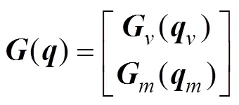


Of note, only the rotation of the manipulator around the-axis in the body-fixed coordinate system is considered in this study. In addition, the vehicle and manipulator are considered rigid bodies, and the manipulator is assumed to be made up of cylindrical elements.
The AUVMS consists of a 6-DOF vehicle and 3-DOF manipulator. Therefore, the system has more DOFs than the task space, making it kinematically redundant. The trans- formation relationship from the task space coordinates to system states (configuration space) is given by Ismail and Dunnigan, (2011):

To accurately perform underwater operations with the AUVMS, the complex underwater environment should be modeled and analyzed. A cylindrical element moving in deep water with densitywill have hydrodynamic forces acting on it, which will be discussed in the next section.
2.1 Added Mass


2.2 Buoyancy
The buoyancy force vector is given by

whereandare the resultant forces and moment of buoyancy and gravity;anddenote the buoyancy and gravity force vectors; andandrepresent the position vectors of the buoyancy and mass centers, respectively.
2.3 Lift and Drag Forces
The lift and drag forces refer to the forces acting on the body due to vortex shedding, pressure, and viscous forces. When a rigid body moves in the fluid, the lift forces are orthogonal to the fluid velocity and drag forces are parallel to it.
First, a first-order Gauss-Markov process is employed to model the kinematics of the ocean currents (Kim., 2014).
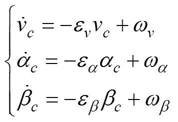
wherevis the ocean current velocity;αandrepresent the orientation of the ocean current;ε,ε, andεare positive constants; andω,ω, andωare the Gaussian white noises.
The dynamic model of drag forceFcan be presented as follows (Fossen, 1994; Avila and Adamowski, 2011):


In underwater environments, the lift forces acting on a rigid body are only caused by vortex shedding and can be expressed as follows (Shah, 2017; Shah and Hong, 2018):

Similarly, both the lift and drag coefficients,CandC, are determined by the Reynolds number Re, angle of attack, and Keulegan-Carpenter number (KC number) (Bay- kal., 2014). The range of values of these coefficients can be empirically determined, as shown in Table 1.
The lift and drag forces are conveniently defined along the relative velocity axis. The frictional force vector can be written as:

whereandare diagonal matrices containing the lift and drag coefficients. Thus, the external hydrodynamic disturbance in this paper can be represented as

whereandare the drag force and lift forces due to vortex shedding, respectively, andis other external unknown and unmeasurable disturbances, such as current loads and diffractions forces.

Table 1 Lift and drag coefficients of a cylinder
To obtain a relatively accurate model of the AUVMS, the following properties are introduced.
Property 1. The maximum angle of the manipulator and the maximal velocity of the vehicle are considered to be finite, which means that vectoris bounded:

Property 2. The inertia matrix() is symmetric and the positive definite function of. The 2-norm of() also is bounded:


where1() and2()arethe position vector scalar-valued functions.


Property 4. There is an upper bound for the Coriolis matrix:
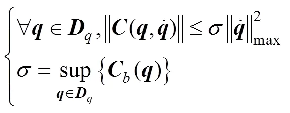
where() is a scalar-valued function of the position vector.
Property 5. In the dynamic model of the AUVMS, the damping matrix is positive definite (Santhakumar and Kim, 2011):

Using the above properties, the upper bound of ‖()‖ can be obtained. To design the control law, the following is defined:
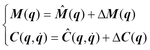
Using Eqs. (1) and (16), the dynamic model of the AUVMS can be rewritten as:

where

3 FSMADRC Design for the AUVMS
In this section, the design problem of SMADRC is stu- died for the AUVMS, which is separated into 9 SISO subsystems for constructing LESO. Then, the estimation error analyses of the LESO and the closed-loop stability of the SMADRC are discussed. Then, an FSMADRC me- thod is developed to self-tune the parameters of the proposed LESO and SMC.
3.1 SMADRC Design
The traditional ADRC is made up of a tracking dif- ferentiator, nonlinear state feedback control law, and a nonlinear ESO, which can deal with unknown distur- bances, coupling effects, and uncertainties. However, the nonlinear functions in the ADRC can be replaced by linear ones to obtain a simpler structure. Hence, the LADRC is adopted here, where the PD controller in the LADRC is replaced by an SMC. For simplicity and no loss of gene- rality, the AUVMS is decomposed into nine subsystems, and an SMADRC is designed for each subsystem in a similar manner to the remaining eight subsystems until an overall SMADRC is obtained for the AUVMS.
The dynamic Eq. (17) of the AUVMS can be rewritten as follows:

whereis the total disturbance given by:

Then, the AUVMS Eq. (18) can be written in an un- folded form as:

Some traditional methods can deal with highly coupled systems (20)feed-forward decoupling algorithms and diagonal matrix decoupling (., Lin and Mon, 2005; Yang., 2012; Yang., 2013; Barbalata., 2018). However, these methods are too complex to apply to an AUVMS case with complex uncertainties and disturbances. In this study, a novel technique is developed to lump the coupling terms from the other subsystems into a total dis- turbance to be estimated by the LESO.
Taking the first subsystem as an example and from Eq. (21), the dynamics of the first subsystem can be written as:

Using the total disturbance concept, Eq. (22) can be re- written as:

where

where1is the total disturbance of the first subsystem, including hydrodynamic forces, coupling terms, Coriolis and centrifugal terms, and other unknown disturbances, and1is the input parameter.
Assumption 1. The derivative of the total disturbance term1exists and it is bounded (Shao and Gao, 2016).

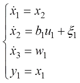
Using Eq. (24), one can propose a LESO as follows:
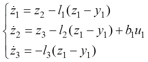
where1,2, and3are the LESO parameters to be deter- mined later. By choosing the parameters in Eq. (26) appro- priately, the outputs of the LESO will converge to1,2, and3(Shao and Gao, 2016).
The observer gains can be given as:

whereω1is the observer bandwidth of the LESO and β, and=1, 2, 3 are selected to ensure that3+12+2+3is a Hurwitz ploynomial. For example, one can let3+12+2+3=(+1), and then the binomial coefficients can be determined by

where=2is the order of the subsystem,.,

Next, before designing the SMADRC scheme for the subsystem Eq. (23), we recall the following lemma.
Lemma 1 (Ioannou and Sun, 1995): For():[0, ∞)Î, if

then() satisfies

The sliding surface is defined as

where1>0 is a given parameter,1=1−1d=1−1d,1is the output of the LESO, and1dis the bounded desired output. Then, an SMC scheme is presented as follows:

Theorem 1: System Eq. (23) with the SMADRC sche- me Eq. (33) and LESO Eq. (26) is considered. Choosing the sliding mode parameter1>1/2 in the SMADRC leads to a bounded closed-loop system tracking error and bounded estimation error of the LESO. Moreover, if parameter1and parameterω1in LESO Eq. (26) are large enough, then the tracking and estimation errors can converge asymptotically to zero. The convergence speed is dependent on parameterω1in the LESO andin the SMC.
Proof. From Eqs. (25) and (26), the error equation of the LESO can be obtained as:
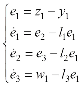
Then, Eq. (34) can be rewritten as follows:

where=[1,2,3]T, and,, andare given as fol- lows:
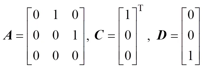
For convenience, the state transformation ofcan be de- fined as follows (Shao and Gao, 2016):
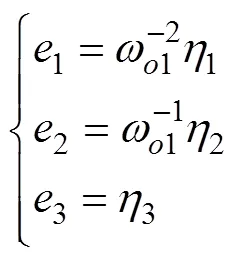
which can be rewritten as

where=[123]T,=[123]T, and=diag{−21,−11, 1}. The combination of Eqs. (35) and (37) obtained

Referring to the definition of Shao and Gao (2016), the error dynamics of LESO can be represented as

where
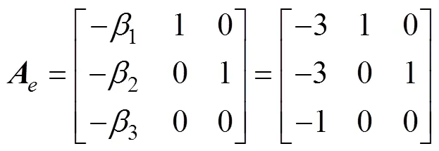
Becauseis a Hurwitz polynomial, for positive matrixthere always exists a positive matrixsatisfying the following Lyapunov equation:

Then, the following Layapunov function is considered:
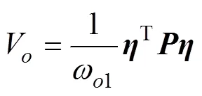
The time differential ofVcan be obtained as
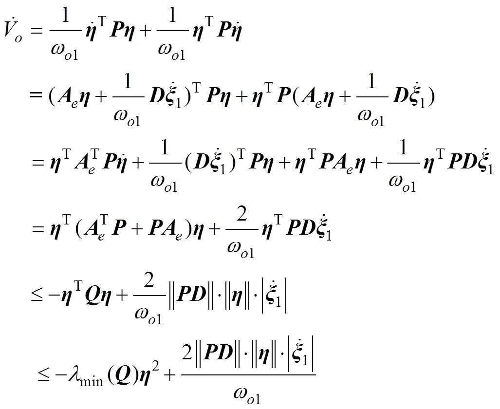

Furthermore, the following Lyapunov function is considered:
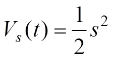
Then, from Eq. (32), the differential ofcan be written as


which can be rewritten as


From Lemma 1,

When1>1/2,

From Eqs. (42) and (44), the following close-loop Lya- punov function is considered:

Using Eqs. (43), (48) and (50) leads to


From Eq. (52), the tracking error of the closed-loop sys- tem converges to a bounded neighborhood of zeros, and the convergence rate of the system is determined by sliding mode parameter1and observer parameterω1. The controllers and their stability for the other subsystems can be established and verified in a similar manner. Eq. (33) clearly shows that only two parameters need to be tuned for the first subsystem. In a similar manner, one can design an SMADRC scheme for each subsystem culminating in the development of an overall SMADRC scheme for the AUVMS with 18 parameters to be tuned, which is less than the number of parameters to be tuned when PID is used instead SMC.
3.2 FSMADRC Design
FLC has been effectively used in the control of com- plex nonlinear systems, which is the main reason why FLC is proposed here for parameter self-tuning. Self-tuning is achieved by using relationships between the tracking errors and parameters of the SMC and LESO. The FLC procedure is demonstrated using the first subsystem of the AUVMS to show how to develop its FSMADRC while considering that the other subsystems are treated in a similar manner. The inputs of the FLC are the error (1) and its derivative (1), in which1=1−1, where1is the desired output and1is the actual system output. The outputs of the FLC are1andω1. In this work, Mamdani’s fuzzy inference rule is adopted. There are seven fuzzy sets of1and1, which consist of negative big (NB), negative medium (NM), negative small (NS), zero (Z), positive small (PS), positive medium (PM), and positive big (PB). There are also three fuzzy sets of1andω, consisting of small (S), medium (M), and big (B). Here, the FLC is designed based on the principle that large errors correspond to low gains and small errors correspond to high gains. Then, the relationship between1and1and parameters1andωis described in the fuzzy language and rules shown in Tables 2 and 3. The fuzzy membership functions(1),(1),(ω1) and(1) are chosen as triangular distributions, as shown in Figs.2 and 3, respectively.
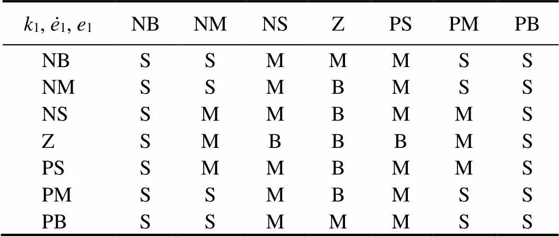
Table 2 Fuzzy rules ofk1
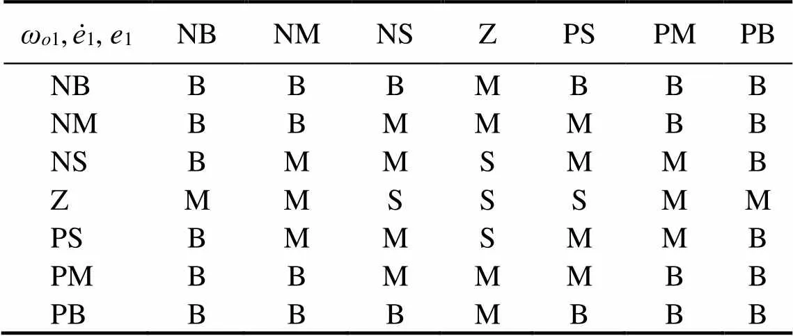
Table 3 Fuzzy rules of ωo1
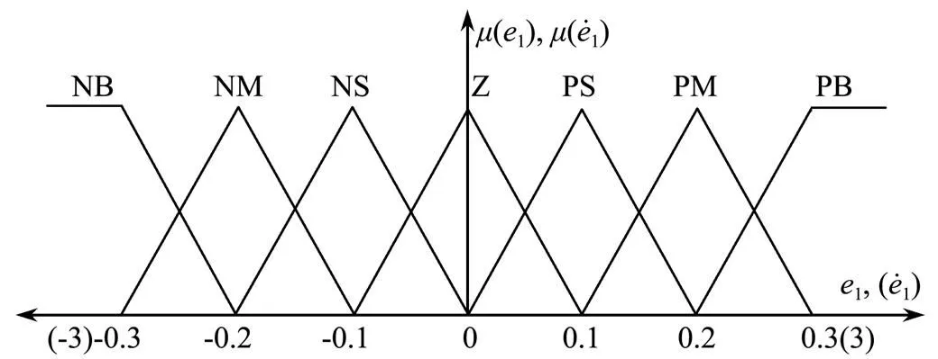
Fig.2 Membership functions of e1 and ė1.
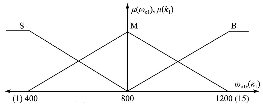
Fig.3 Membership functions of ωo1 and k1.
The fuzzy sets ofandare chosen as [−0.3, 0.3] and [−3, 3], and the fuzzy sets ofω1and1are chosen as [400,1200] and [1, 15], respectively. The structure of the FSMA- DRC is shown in Fig.4. Large values for parameterω1im- prove the effectiveness of the LESO. However, the bandwidth of the LESO can be too large in real-life applications (Gao, 2003), so a balance must be considered between the bandwidth values and their suitability for implementation.
After the design completion of the first FSMADRC, the FSMADRCs for self-tuning the parameters of the re- maining subsystems of the AVUMS can be developed in a similar manner.
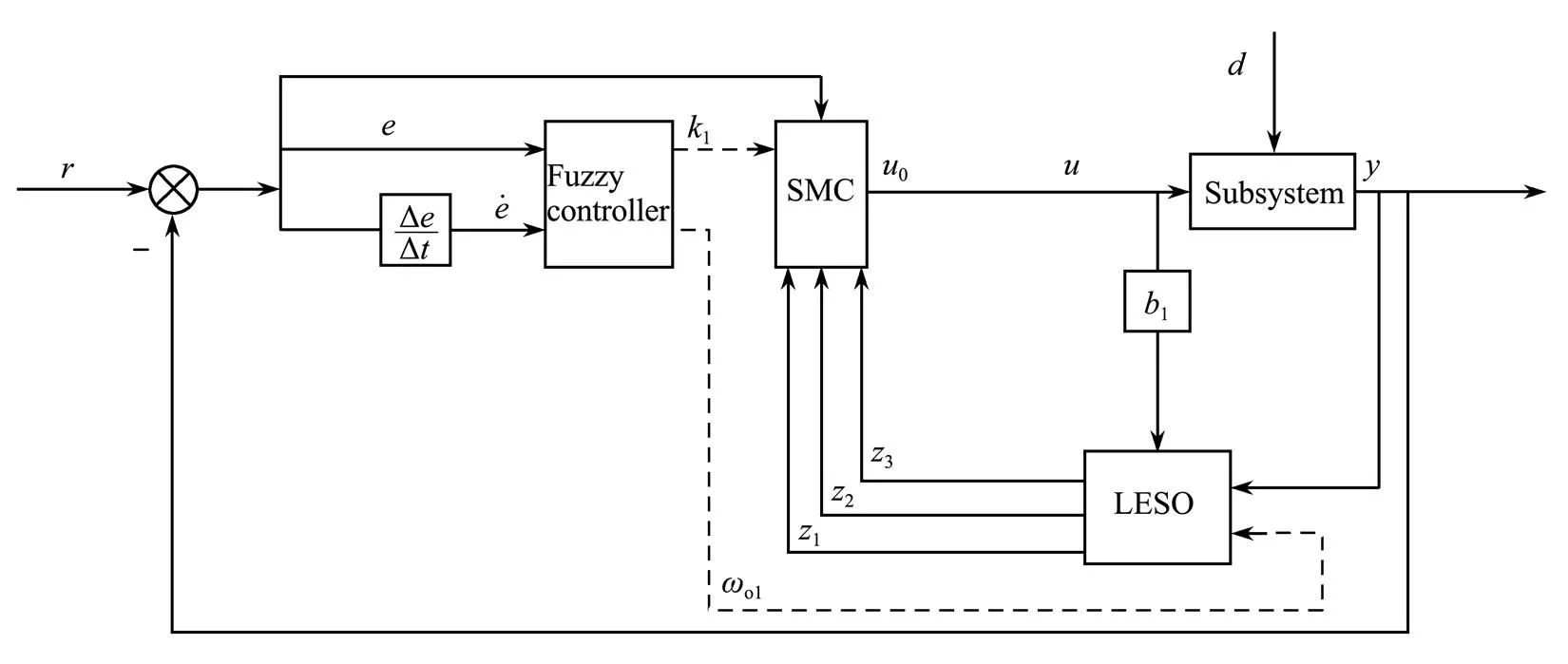
Fig.4 Structure of the FSMADRC.
4 Description of the Tasks
The AUVMS is comprised of a 6-DOF vehicle and 3- DOF manipulator, whose parameters are chosen as Table 4. First, an open-loop analysis is conducted on the AUVMS to analyze the ocean current effects on the vehicle. Then, two typical tasks are carried out to test the control performance of the proposed FSMADRC.
4.1 Task I
In underwater operations, the capability of the AUVMS to keep the arm balanced while moving a grasped object is important. In Task I, the AUVMS is required to move to a specified location to pick weights, move the weights to another location, and then return to the starting point. Therefore, the AUVMS will move from position [0.012−4.71−2.885]Tat time=0s in the earth-fixed coordinate system to the pick-up point [5.78−4.69−0.13]Tat time=5s along the first desired trajectory to pick up an object with 3.25kg weight. When the AUVMS arrives at the drop- off point at=10s following the second trajectory, the object will be dropped off there. Then, following a third desired trajectory, the vehicle reverses the course to the stop position at [3.945−3.412−5.03]Tand reaches it time=15s. The joint angles of the manipulator are kept at [123]T= [60˚30˚20˚]T.
The desired motion trajectories of the vehicle are chosen as a cubic time polynomial given by
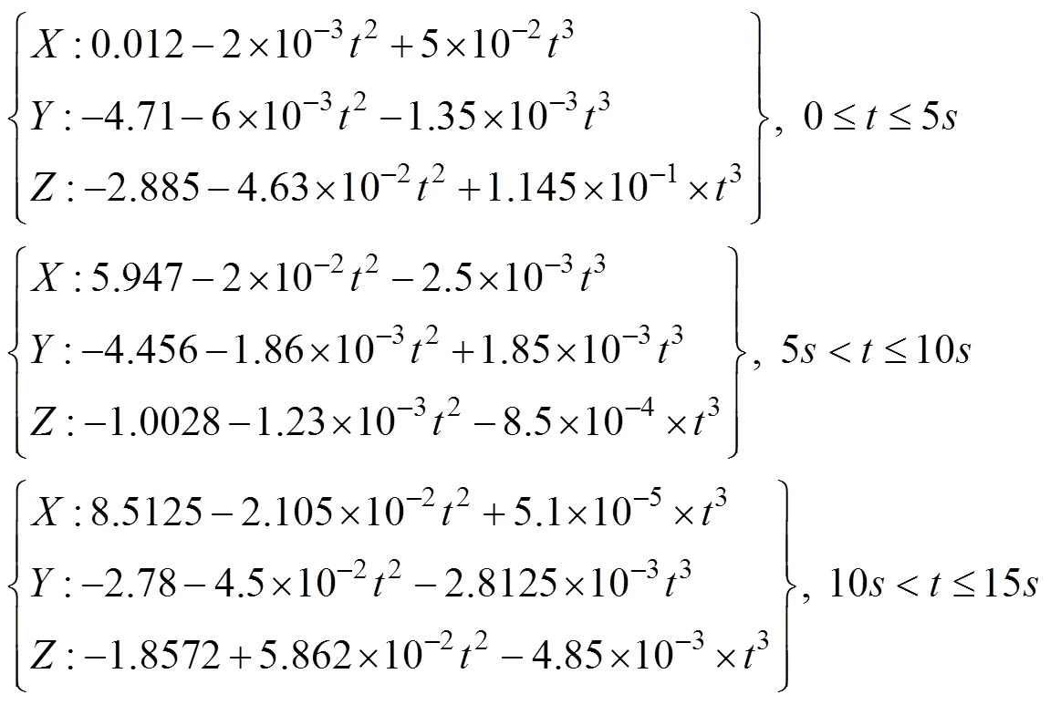
To reduce the power consumption of the vehicle when moving in deep waters, the frequent switching of the rud- der angle should be avoided. Therefore, the amplitude of the variation of the path angles (roll, yaw, and pitch angles) should also be included in the closed-loop system.
4.2 Task II
The inertia coupling forces always act on the vehicle to force it to vibrate when the manipulator swings at a high frequency. The accuracy of the hovering operations of the AUVMS is important to study; therefore, in Task II, the AUVMS is required to hover at a fixed position. Task II is designed to test the capability of the FSMADRC in dealing with rapidly changing external forces and high coup- ling effects. In this task, only the angles of the manipulator joints are allowed to vary, and the vehicle is kept in still mode. The working position of the AUVMS is set as [0 0 0]Tin the earth-fixed coordinate frame.
In addition, during the moving process, the roll, yaw, and pitch angles of the vehicle remain at zero, whereas the joints’ angle trajectories of the manipulator are given by

5 Simulations and Discussion
In this section, the control performance of the FSMA- DRC will be studied, and compared with PID controllers andclassic FLC (CFLC), which are chosen respectively as

whereK,K, andKare the parameters of the PID controller,Kis the output scaling gain of the CFLC controller, andCFLCis its control output.
In accordance with the membership functions in Tasks I and II, the fuzzy sets for both tasks are chosen as [−0.3,0.3] for the error, [−3,3] for the derivative of the error, [1,15] for the bandwidth of the controller, and [400, 1200] for the bandwidth of the observer. Here, all SMC para- meters c,=1, …, 9of the subsystems are set to be 10.
5.1 Results of Task I
The simulation results of Task I are shown in Figs.5–11. The 3D view of the moving trajectories of the center of gravity of the vehicle controlled by different controllers are depicted in Fig.5. The tracking errors are shown in Fig.6, which also shows that the FSMADRC can track the desired trajectories more accurately than the CFLC and PID, especially during picking up and dropping off the weights.
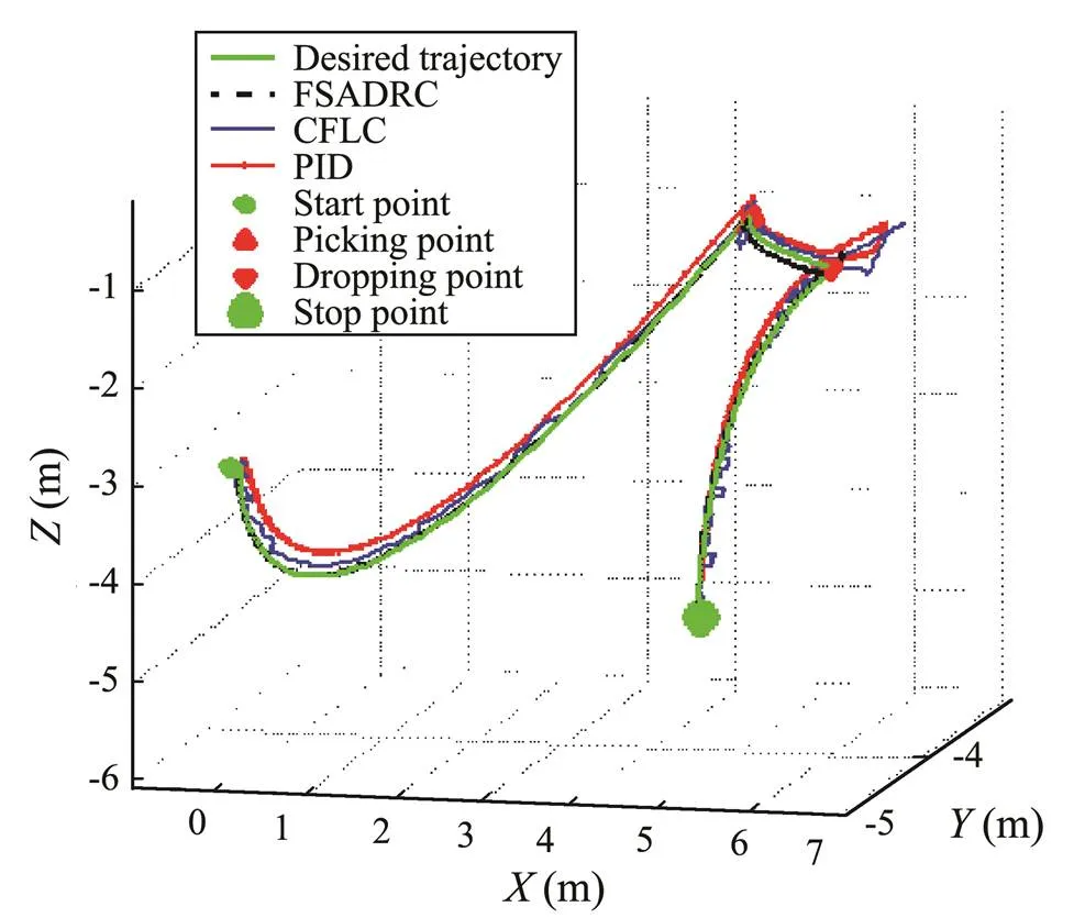
Fig.5 Trajectory of the AUV in Task I in a 3D view: (green) desired trajectory, (dashed-black) using FSADRC, (blue) using CFLC, (red) using PID control.
The LESO can estimate the disturbance resulting from the additional load weight picked up by the AUVMS and cancel its effect in the closed-loop system. Thus, the proposed method can ensure that the FSMADRC spends less buffering time to track the desired trajectories.

Fig.6 Trajectories of the tracking error of the AUV in Task I: (black) using FSMADRC, (blue) using CFLC, and (red) using PID control.
Fig.7 shows that the proposed FSMADRC can keep the manipulator stable when picking up and dropping off the load weight and spends less time restoring the original angles. However, the other two controllers were not able to achieve this objective. Next, as shown in Fig.8, the roll, yaw, and pitch angle trajectories resulting from using the FSMADRC switch much more smoothly than those resulting from the PID and CFLC schemes. Moreover, the FSMADRC achieves better control performance with less energy consumed than the CFLC and PID, as shown in Fig.9. The disturbance estimation performance of the LESOs is shown in Fig.10, in which1–9correspond to the total disturbance estimation errors of the LESO in each of the nine subsystems. Clearly, the estimation errors converge to a small neighborhood of zero, which ensures an effective rejection of the total disturbance.
5.2 Results of Task II
The simulation results of Task II are presented in Figs.11–14. Figs.11 and 12 show that the proposed method can track the swaying trajectories and keep the vehicle stable in a fixed position relatively better than the PID and CFL control schemes. In addition, the yaw angle of the AUV- MS under the FSMADRC exhibits better stability performance than that under the other two controllers. Fig.13 shows that the FSMADRC demonstrates better performance intrajectory tracking by the end effector than that under the PID or CFL control scheme. Moreover, the FS- MADRC consumes less energy than the other two contro- llers while performing Task II, as shown in Fig.14.
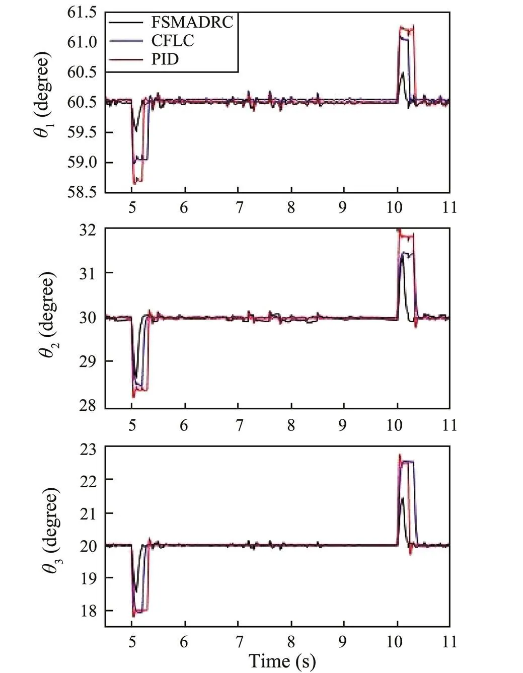
Fig.7 Trajectories of joint angles of the AUVMS in Task I: (black) using FSMADRC, (blue) using CFLC, and (red) using PID control.

Fig.8 Path angle of the AUV in Task I: (black) using FS- MADRC, (blue) using CFLC, and (red) using PID control.
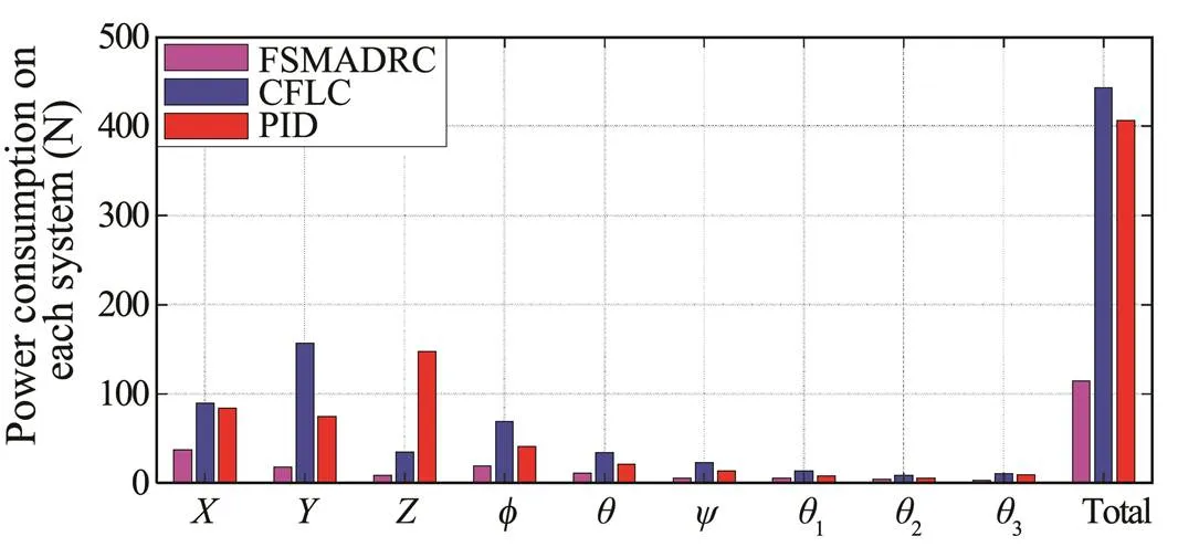
Fig.9 Comparison of the power consumption in Task I.
6 Conclusions
Underwater robotics has attracted a lot of attention from the research community for applications previously deemed impossible to be performed by humans. Applica- tions, such as surveys, security, explorations, subsea en- gineering, and oil/gas explorations, require spot discover- ries and manipulation. Oftentimes, the aforementioned tasks/ missions are executed using ROVs or divers, which is costly and often puts human life at risk. Underwater vehicles equipped with manipulator(s) have proven to provide a cost-effective solution to deep-sea missions and put hu- man operators out of harm’s way. An underwater vehicle equipped with a two-link and three-joint manipulator is studied here for performing routine tasks under uncertain and harsh environmental conditions. The FSMADRC me- thod is used in the closed-loop system to address the tracking problem of the AUVMS, and the results are com- pared with those of the commonly used PID and CFL control schemes. The simulation results show that FSMA- DRC achieves better control performance than the PID and CFLC schemes. The proposed FSMADRC is independent of the AUVMS model and only needs limited knowledge of the system’s model. Finally, the proposed scheme achieves better control performance than the other two reference control methods with less power consum- ption. In addition, the FSMADRC can determine (self- tune) the appropriate parameters adaptively, which makes it very suitable for real-life applications and can be easily extended to other vehicle systems.
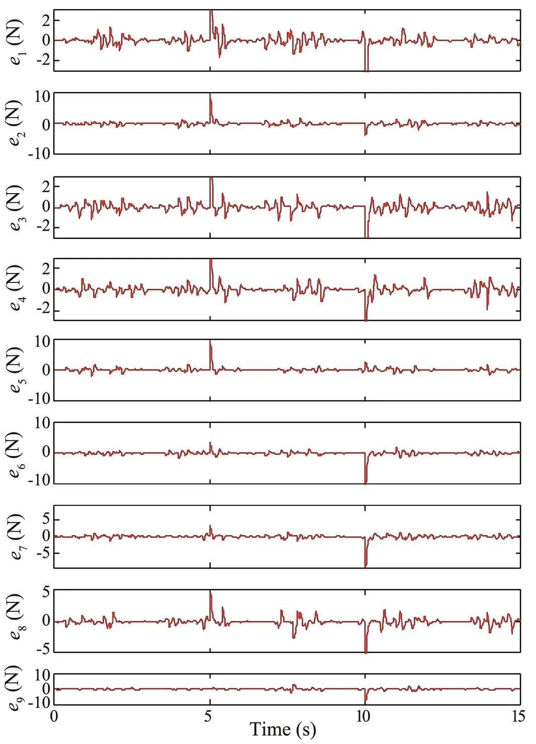
Fig.10 Total disturbance estimation error of each LESO in Task I.
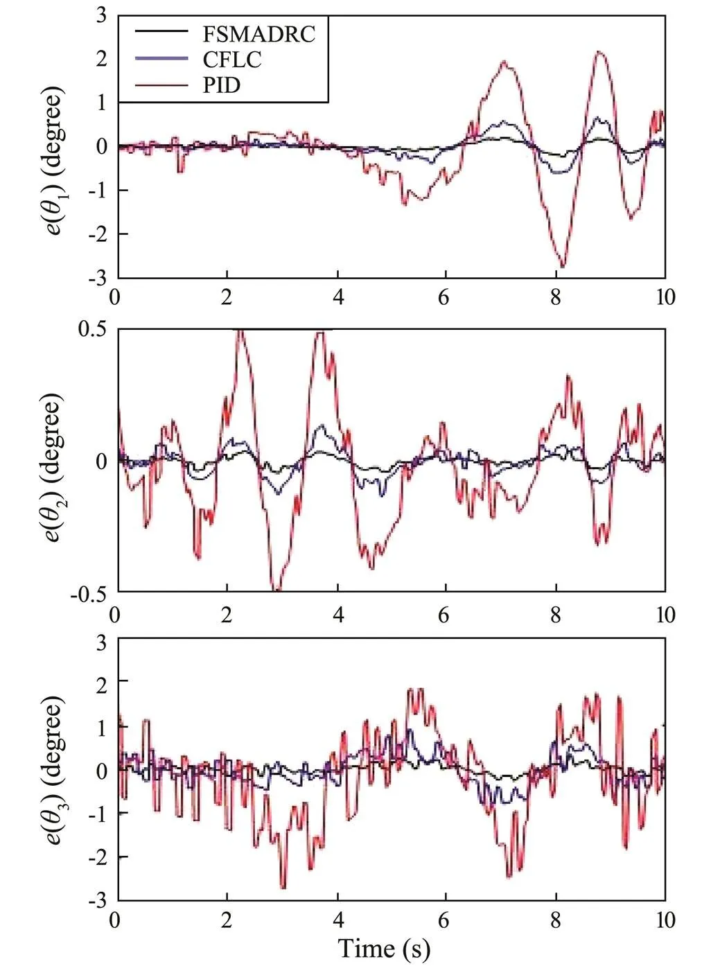
Fig.11 Trajectory tracking errors of the joint angles of the AUVMS in Task II: (black) using FSMADRC, (blue) using CFLC, and (red) using PID control.

Fig.12 Position response and yaw angle of the AUV in Task II: (black) using FSMADRC, (blue) using CFLC, and (red) using PID control.
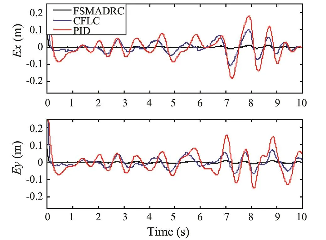
Fig.13 Trajectory tracking errors of the end effector of the AUVMS in Task II: (black) using FSMADRC, (blue) using CFLC, and (red) using PID control.
Acknowledgements
This work is supported in part by the Fundamental Research Funds for the Central Universities (No. 201964012), the Open Foundation of Henan Key Laboratory of Under- water Intelligent Equipment (No. KL02A1802), and the National Natural Science Foundations of China (Nos. 61603361 and 51979256), the Shandong Provincial Natural Science Foundation (No. ZR2017MEE015).
Avila, J. P., and Adamowski, J. C., 2011. Experimental evaluation of the hydrodynamic coefficients of a ROV through Morison’s equation., 38 (3): 2162-2170, DOI: 10.1016/j.oceaneng.2011.09.032.
Barbalata, C., Dunnigan, M., and Petillot, Y., 2018. Coupled and decoupled force/motion controllers for an underwater vehicle- manipulator system., 96 (6): 1-23, DOI: 10.3390/jmse6030096.
Baykal, C., Sumer, B. M., Fuhrman, D. R., Jacobsen, N. G., and Fredsøe, J., 2014. Numerical investigation of flow and scour around a vertical circular cylinder., 373 (2033): 20140104, DOI: 10.1098/rsta.2014. 0104.
Chen, W., Yang, J., Guo, L., and Li, S., 2016. Disturbance observer based control and related methods–An overview., 63 (2): 1083-1095, DOI: 10.1109/TIE.2015.2478397.
Cieslak, P., Ridao, P., and Giergiel, M., 2015. Autonomous underwater panel operation by GIRONA500 UVMS: A practical approach to autonomous underwater manipulation.. Seattle, WA, 529-536, DOI: 10.1109/icra.2015.7139230.
Du, B., Wu, S., Han, S., and Cui, S., 2016. Application of linear active disturbance rejection controller for sensorless control of internal permanent-magnet synchronous motor., 63 (5): 3019-3027, DOI: 10. 1109/TIE.2016.2518123.
Esfahani, H. N., Azimirad, V., and Danesh, M., 2015. A time de- lay controller included terminal sliding mode and fuzzy gain tuning for underwater vehicle manipulator systems., 107: 97-107, DOI: 10.1016/j.oceaneng.2015.07. 043.
Fossen, T. I., 1994..John Wiley & Sons, Chichester, 99-113, DOI: 10.1016/0005- 1098(96)82331-4.
Fu, C., and Tan, W., 2016. Linear active disturbance rejection control: Analysis and tuningIMC., 63 (4): 2350-2359, DOI: 10.1109/tie. 2015.2505668.
Gao, Z., 2003. Scaling and bandwidth-parameterization based controller tuning.. Denver, 4989-4996, DOI: 10.1109/ACC.2003.1 242516.
Gao, Z., Huang, Y., and Han, J., 2002. An alternative paradigm for control system design., 25 (5): 4578-4585, DOI: 10.1109/cdc.2001.980926.
Guerra, R. E. H., Schmitt-Braess, G., and Haber, R. H., 2003. Using circle criteria for verifying asymptotic stability in PI- like fuzzy control systems: Application to the milling process.–, 150 (6): 619-628, DOI: 10.1049/ip-cta:20030795.
Han, J., 1998. Active disturbance rejection controller and its applications., 13 (1): 19-23 (in Chinese with English abstract).
Huang, Y., and Xue, W., 2014. Active disturbance rejection control: Methodology and theoretical analysis., 53 (4): 963-976, DOI: 10.1016/j.isatra.2014.03.003.
Huang, H., Tang, Q., Li, H., Le, L., Li, W., and Pang, Y., 2016. Vehicle-manipulator system dynamic modeling and control for underwater autonomous manipulation., 47 (3): 125-147.
Ioannous, P. A., and Sun, J., 1995.. Pren- tice-Hall, Englewood Cliffs, NJ, 1-24, DOI: 10.1007/978-1-44 71-5058-9_118.
Ismail, Z. H., and Dunnigan, M. W., 2011. Tracking control sche- me for an underwater vehicle-manipulator system with single and multiple sub-regions and sub-task objectives., 5 (5): 721-735, DOI: 10.104 9/iet-cta. 2010.0174.
Kim, Y., Mohan, S., and Kim, J., 2014. Task space-based control of an underwater robotic system for position keeping in ocean currents., 28 (16): 1109-1119, DOI: 10. 1080/01691864.2014.913504.
Klein, C. A., and Huang, C. H., 1983. Review of pseudoinverse control for use with kinematically redundant manipulators., 13 (2): 245-250, DOI: 10.1109/TSMC.1983.6313123.119.
Korkmaz, O., Ider, S. K., and Özgören, M. K., 2013. Control of an underactuated underwater vehicle manipulator system in the presence of parametric uncertainty and disturbance.. Washington, D. C., 578-584, DOI: 10.1109/ACC.2013.6579899.
Li, J., Xia, Y., Qi, X., and Gao, Z., 2016. On the necessity, scheme and basis of the linear-nonlinear switching in active disturbance rejection control., 62 (2): 1425-1435, DOI: 10.1109/TIE.2016.261 1573.
Li, X. G., Wang, H. D., Li, M., Ling, Z., Xiao, H., and Hou, D., 2018. Linear active disturbance rejection controller design for underwater vehicle manipulators with 2-links., 18 (8): 875-880, DOI: 10. 1109/CAC.2018.8623694.
Lin, C. M., and Mon, Y. J., 2005. Decoupling control by hierarchical fuzzy sliding-mode controller., 13 (4): 593-598, DOI: 10.1109/t cst.2004.843130.
Liu, X., Tang, L., and Zhou, L., 2011. Fuzzy active disturbance re- jection control of three-motor synchronous system., 13 (4): 51-57, DOI: 10. 1109/tcst.2004.843130.
Mamdani, E. H., and Assilian, S., 1975. An experiment in linguistic synthesis with a fuzzy logic controller., 7 (1): 1-13, DOI: 10.1016/S0020- 7373(75)80002-2.
Marani, G., Choi, S. K., and Yuh, J., 2009. Underwater autonomous manipulation for intervention missions AUVs., 36 (1): 15-23, DOI: 10.1016/j.oceaneng.2008.08.007.
Mohan, S., and Kim, J., 2015. Coordinated motion control in task space of an autonomous underwater vehicle-manipulator system., 104: 155-167, DOI: 10.1016/j.ocean eng.2015.05.011.
Morales, R., Sira-Ramírez, H., and Somolinos, J. A., 2015. Linear active disturbance rejection control of the hovercraft vessel model., 96: 100-108, DOI: 10.1016/j. oceaneng.2014.12.031.
Pan, W., Xiao, H., and Wang, C., 2010. Design of ship course controller based on optimal active disturbance rejection technique. In:. Lin, S., and Huang, X., eds., Springer, Berlin, 232-236.
Ramírez-Neria, M., Sira-Ramírez, H., Garrido-Moctezuma, R., and Luviano-Juárez, A., 2014. Linear active disturbance rejection control of underactuated systems: The case of the Furuta pendulum., 53 (4): 920-928, DOI: 10.1016/j. isatra.2013.09.023.
Ran, M., Wang, Q., and Dong, C., 2016. Stabilization of a class of nonlinear systems with actuator saturationactive disturbance rejection control., 63: 302-310, DOI: 10. 1016/j.automatica.2015.10.010.
Sagara, S., Yatoh, T., and Shimozawa, T., 2010. Digital RAC witha disturbance observer for underwater vehicle-manipulator systems., 15 (3): 270-274, DOI: 10.10 07/s10015-010-0806-7.
Santhakumar, M., and Kim, J., 2011. Modelling, simulation and model reference adaptive control of autonomous underwater vehicle manipulator systems.. Gyeonggi-do, 643-648, DOI: doi.org/10.1049/ip-cta:20030795.
Shah, U. H., and Hong, K. S., 2018. Active vibration control of a flexible rod moving in water: Application to nuclear refueling machines., 93: 231-243, DOI: 10.1016/j.auto matica.2018.03.048.
Shah, U. H., Hong, K. S., and Choi, S. H., 2017. Open-loop vibration control of an underwater system: Application to refueling machine., 22 (4): 1622-1632, DOI: 10.1109/TMECH.2017.2706304.
Shao, S., and Gao, Z., 2016. On the conditions of exponential stability in active disturbance rejection control based on singular perturbation analysis., 90 (10): 2085-2097.
Simetti, E., and Casalino, G., 2016. Manipulation and transportation with cooperative underwater vehicle manipulator systems., 42 (4): 1-18, DOI: 10.1109/JOE.2016.2618182.
Su, T. J., Wang, S. M., Tsai, S. H., and Tsou, T. Y., 2017. Design of fuzzy and linear active disturbance rejection control for insulin infusion in type 1 diabetic patients., 19: 1966-1977, DOI: 10.1007/s40815- 017-0318-x.
Sugiyama, N., and Toda, M. A., 2016. Nonlinear disturbance ob- server using delayed estimates its application to motion control of an underwater vehicle-manipulator system. 2016. Daejeon, 2007-2013, DOI: 10.1109/IROS.2016.7759316.
Sun, Z., Zheng, J., Man, Z., Wang, H., and Lu, R., 2018. Sliding mode-based active disturbance rejection control for vehicle steer-by-wire systems., 3 (1): 1-10, DOI: 10.1049/iet-cps.2016.0013.
Wang, Y., Jiang, S., Chen, B., and Wu, H., 2017. Trajectory tracking control of underwater vehicle-manipulator system using discrete time delay estimation., 99 (5): 7435-7443, DOI: 10.1109/ACCESS.2017.2701350.
Xu, T., Wang, J., Shi, W., Wang, J., and Chen, Z., 2019. A Localization algorithm using a mobile anchor node based on region determination in underwater wireless sensor networks., 18 (2): 394-402, DOI: 10.1007/s11802-019-3724-x.
Yang, H., Sun, J., Xia, Y., and Zhao, L., 2018. Position control for magnetic rodless cylinders with strong static friction., 65 (7): 5806-5815, DOI: 10.1109/TIE.2017.2782198.
Yang, M., Li, R., and Chu, T., 2013. Controller design for disturbance decoupling of Boolean control networks., 49 (1): 273-277, DOI: 10.1016/j.automatica.2012.10.010.
Yang, Q., Su, H., and Tang, G., 2016. Approximate optimal tracking control for near-surface AUVs with wave disturbances., 15 (5): 789-798, DOI: 10.1007/s11802-016-2986-9.
Yang, Y. P., Zhao, Y. X., Hao, Y. L., and Du, H. Y., 2012. Decoupling control system for AUV hovering near-surface., 34 (3): 572-577 (in Chinese with English abstract).
Zhang, W., Xu, H., and Ding, X., 2015. Design and dynamic analysis of an underwater manipulator.,338: 399-409, DOI: 10.1007/978-3-662-46466-3_40.
. E-mail: liqin72@126.com
June 27, 2019;
November 4, 2019;
January10, 2020
(Edited by Chen Wenwen)
杂志排行
Journal of Ocean University of China的其它文章
- Phaeocystis globosa Bloom Monitoring: Based on P. globosa Induced Seawater Viscosity Modification Adjacent to a Nuclear Power Plant in Qinzhou Bay, China
- Effect of pH, Temperature, and CO2 Concentration on Growth and Lipid Accumulation of Nannochloropsis sp. MASCC 11
- The 9–11 November 2013 Explosive Cyclone over the Japan Sea- Okhotsk Sea: Observations and WRF Modeling Analyses
- Real-Time Position and Attitude Estimation for Homing and Docking of an Autonomous Underwater Vehicle Based on Bionic Polarized Optical Guidance
- Characterization of the Complete Mitochondrial Genome of Arius dispar (Siluriformes: Ariidae) and Phylogenetic Analysis Among Sea Catfishes
- Establishment and Characterization of Four Long-Term Cultures of Neural Stem/Progenitor Cell Lines from the Japanese Flounder Paralichthys olivaceus
