Real-Time Position and Attitude Estimation for Homing and Docking of an Autonomous Underwater Vehicle Based on Bionic Polarized Optical Guidance
2020-09-28CHENGHaoyuanCHUJinkuiZHANGRanGUIXinyuanandTIANLianbiao
CHENG Haoyuan, CHU Jinkui, ZHANG Ran, GUI Xinyuan, and TIAN Lianbiao
Real-Time Position and Attitude Estimation for Homing and Docking of an Autonomous Underwater Vehicle Based on Bionic Polarized Optical Guidance
CHENG Haoyuan, CHU Jinkui*, ZHANG Ran, GUI Xinyuan, and TIAN Lianbiao
The Key Laboratory for Micro/Nano Technology and System of Liaoning Province, Dalian University of Technology, Dalian 116024, China
As an important tool for marine exploration, the autonomous underwater vehicle (AUV) must home in and dock at a docking station (DS) to be recharged, repaired, or to exchange information at set intervals. However, the complex and hostile underwater environment makes this process challenging. This study proposes a real-time method based on polarized optical guidance for determining the position and attitude of the AUV relative to its DS. Four polarized artificial underwater landmarks are positioned at the DS, which are recognized by the AUV vision system. Compared with light intensity, the polarization of a light beam is known to be better maintained at greater propagation distances, especially in underwater environments. The proposed method, which is inspired by the ability of marine animals to communicate, calculates the pose parameters in less than 10ms without any other navigational information. The simulation results reveal that the angle errors are small and the position errors are no more than 0.116m within 100m in the coastal ocean. The results of underwater experiments further demonstrate the feasibility of the proposed method, which extends the operating distance of the AUV beyond what is currently possible while maintaining the precision of traditional optical guidance.
polarization; optical guidance; AUV; underwater docking; position and attitude estimation
1 Introduction
As a powerful tool for ocean exploration and the development of sub-sea infrastructure, the autonomous underwater vehicle (AUV) is playing an increasingly important role in military and scientific research. However, due to its limited operational hours, the AUV must be frequently recharged and relaunched and the complex and hostile underwater environment increases the difficulty of this process. Therefore, a reliable homing and docking technology is crucial for the AUV to be able to complete its missions.
To determine its position and attitude relative to the docking station (DS), the AUV can be equipped with various sensors,, acoustic, electromagnetic, and optical. Compared to other technologies, optical guidance has good directional accuracy, low vulnerability to external detection, and a diverse range of uses (Deltheil, 2002). The optical docking system provides a targeting accuracy on the order of 1cm in real-life conditions, even in turbid bay waters (Cowen, 1997). However, its operating distance is limited because of the underwater conditions. Yu(2001) proposed a navigation method for the AUV based on artificial underwater landmarks (AULs), which can be recognized by a vision system installed in anAUV. Lee(2003) presented a docking system for AUVs that enable them to dock at an underwater station with the aid of a camera installed at the center of the AUV nose. A docking method based on image processing for cruising-type AUVs was proposed by Park(2009), and a similar docking method for hovering-type AUVs was proposed by Kondo(2012). Maki(2013) proposed a docking method for hovering-type AUVs based on both acoustic and visual positioning, and Yahya and Arshad (2015) proposed a tracking method based on the placement of colored markers in the cluttered environment. Vallicrosa(2016) developed a light beacon navigation system for estimating the position of the DS with respect to the AUV.
All the above mentioned optical guidance systems for AUV homing and docking have established that optical guidance technology is highly feasible and has reliable precision, especially at short distances. However, underwater imaging poses significant challenges at extended ranges compared to similar situations over the ocean surface. Even in the clearest ocean waters, the visibility range, at best, is on the order of 10m owing to the absorption and scattering of light by particles of various origins, including algal cells, detritus, sediments, plankton, and bubbles (Hou, 2009). Therefore, extending the operating range while maintaining the precision of the optical guidance system is the main technological challenge of AUVs. As an information carrier, the characteristics of polarized light, such as the degree of polarization (DOP), have greater robustness than light intensity (Xu, 2015). More than 70 underwater species (Horváth and Varjú, 2004) are polarization-sensitive and some have the ability to navigate, hunt, camouflage themselves, and communicatepolarized vision (Shashar, 2000; Waterman, 2006; Cartron, 2013). Polarization has been found to increase the contrast and detection range in scattering media both above and under water (Schechner, 2003; Schechner and Karpel, 2005). In addition, bionic polarization navigation technology has the potential for application in water (Cheng, 2020).
In this paper, we propose a real-time method for homing and docking the AUV by determining its position and attitude relative to polarized AULs on the DS, which are recognized by a vision system installed in the AUV. We introduce the theory of polarization imaging, along with the concept of polarized optical guidance. Then, we obtain atmospheric intensity and DOP images and simulate underwater intensity and DOP images at various distances. Pixel-recognition errors are input into the model to calculate the pose errors. We conduct underwater experiments to determine the practicability of the proposed method and the results indicate that the polarized optical guidance system extends the operating distance while maintaining the precision of traditional optical guidance. This biologically inspired polarized optical guidance mechanism provides a novel approach for AUV homing and docking that enables AUVs to perform tasks at much greater distances.
2 Methods
2.1 Theory of Polarization Imaging
Generally, vision systems recognize the intensity characteristic of AULs, whereas the proposed method recognizes the DOP of the polarized AULs. The DOP is the ratio of the component magnitude of the polarized light to the total magnitude of the light, which can vary between 0 (completely unpolarized light) and 100% (completely polarized light).To obtain a DOP image, the DOP of every pixel of the image is calculated and the Stokes vectoris used to describe the polarized light beam. All information about the polarized light is contained in the four components of Eq. (1):

whereis the total intensity of the light,is the fraction of linear polarization parallel to a reference plane,is the proportion of linear polarization at 45˚ with respect to the reference plane, andis the fraction of right-handed circular polarization.The linear polarization is used to format the image. The polarization state of the incident light=[,,,]T, which is changed by a polarizing film, can be expressed based on the Muller matrix:

whereis the angle between the main optical axis and the zero reference line and=[,,,]Tis the polarization state of the emergent light. Here the first row of the Muller matrix is relevant because the light intensity can be obtained directly by the camera:

Therefore, if the light intensities of the emergent light at three differentvaluesare known, the,,andvalues ofthe incident beam can be calculated. If we setto 0˚, 45˚, and 90˚, the following equation set is obtained:
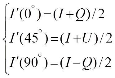
The equation set is then transformed as follows:
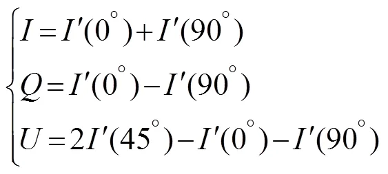
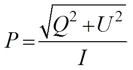
Then, the linear DOP is calculated and a DOP image is obtained:
The precision of the homing and docking process depends on the image quality. To better evaluate the image quality, we introduce the parameter:
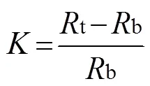
wheretis the intensity or DOP of the target andbis the intensity or DOP of the background in the image.
2.2 Polarized Optical Guidance
Polarization imaging, which enables the contrast of target images to be increased and both the illumination effects and backscattering to be decreased, is an ideal technique for underwater target detection, as it is simple to implement, requires little power, and can be used in real-time applications (Dubreuil, 2013).In addition, in the deep sea, there is no daylight, which means point-like bioluminescence is the only light source (Warrant and Locket, 2004). To survive in the dark ocean environment, marine creatures have evolved to acquire polarization sensitivity, which they use for navigation, predation, disguise, and communication in the same way as humans use intensity information. Inspired by these marine creatures, we design a method for determining the position and attitude of the AUV based on polarized AULs, which are recognized by a camera installed in the AUV, as shown in Fig.1. A light source with a wavelength of 532nm is employed because of its greater propagation distance. We use a normal lightsource rather than laser light because AUVs have difficulty recognizing laser light, which is unidirectional, despite its greater propagation distance.
The proposed system consists of a camera and four AULs, which are polarized light beacons situated in the DS. As the light source is polarized, its DOP is greater than that of the background. The pixel center of each AUL can be identified by finding the maximum DOP point in the image, for which the corresponding pixel coordinates can be obtained. Figs.2 and 3 show the DS, image, and the camera coordinate system at long and short distances, respectively. Fig.4 shows the positions of the four light beacons in the image during the docking process. When the AUV is far away from the DS, the four light beacons appear to be locatedinoneplace on the edge of the AUV vision system, as shown in Figs.2 and 4(a). The angles of rotation,andabout the-axis and-axis, respectively can be calculated as shown in Eq. (8):
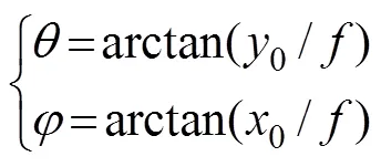
where x0 and y0 are the respective horizontal and vertical coordinates of the camera coordinate system, which can be calculated based on the physical pixel size of the camera and the coordinates of the image coordinate system. The pixel coordinates of the light beacons are obtained by image processing. f is the focal length of the camera.
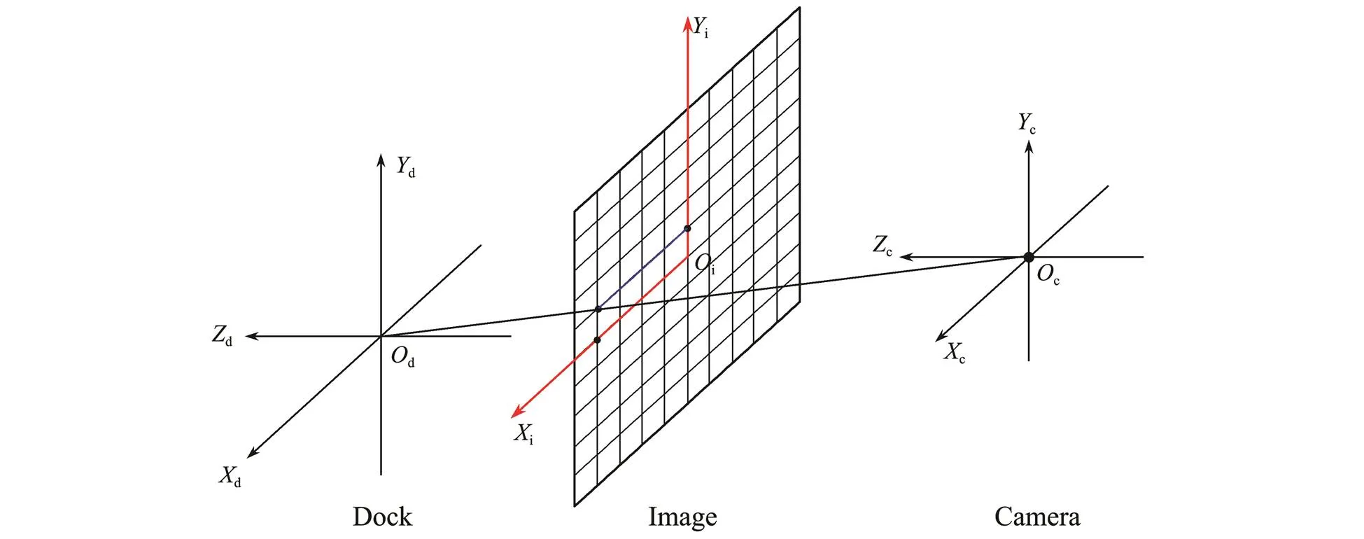
Fig.2 Coordinate system of polarized optical guidance at a large distance.
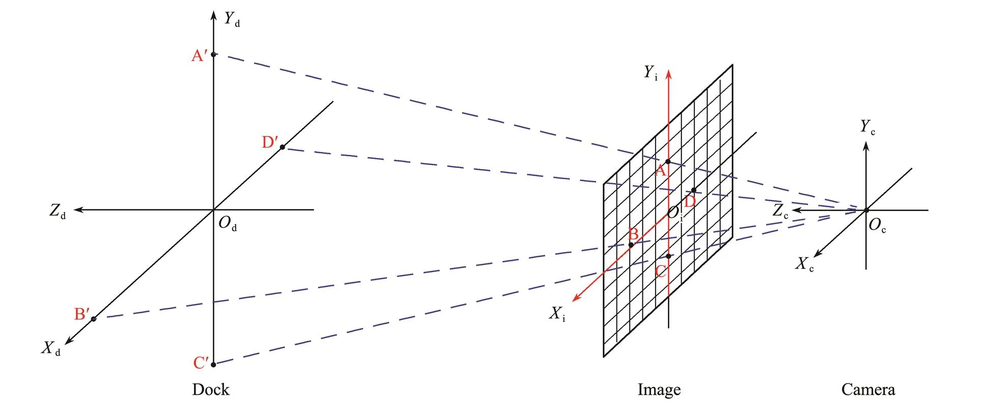
Fig.3 Coordinate system of polarized optical guidance at a close distance.
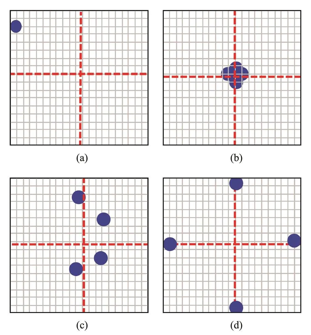
Fig.4 Positions of four light beacons in the image during the docking process. (a), (b), (c), and (d) represent different stages of the docking process.
At a distance, the AUV approaches the DS based on two angles. As the AUV nears the DS, the four polarized light beacons appear in the AUV vision system, as shown in Figs.3, 4(b), and 4(c). Safe and accurate homing and docking of the AUV depends on the precise determina-tion of the position and attitude of the AUV relative to the DS. It is a perspective--point (PNP) problem, in which the position and attitude of the AUV are determined on the relationship of the positions of the polarized AULs in the image and actual situation whenthe number of AULsisin computervision. Fischler and Bolles (1987) proved that solving a PNP problem and obtaining a unique solution requires at least four coplanar feature points. The PNP problem simplifies the proposed method into a three-dimensional quadratic system of equations:
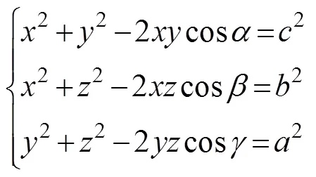
where,, andarethe respective anglesamong OcA, OcB, and OcC.,, andare the respective distances between A, B, and C, which are known beforehand. Then,,,and, which are the respective lengths of AOc, BOc, and COc,are known. However, the equation has multiple solutions, and therefore, a fourth point is needed to obtain a unique solution. Coupled with the coordinates for A, B, and C in the camera coordinate system, the coordinates for A, B, and Cin the camera coordinate system are obtained. Finally, we use a matrixforcoordinatetransformation to solve for the six position and attitude parameters of the camera relative to the AULs, as shown below:

where the positions of the camera relative to the AULs areT,T, andT, and the attitudes are,, and. (,,) and (,,) are the coordinates of the AULs relative to the DS and the camera coordinate system. Fig.5 shows the complete solution process, for which the total computing time is no longer than 10ms. When the AUV is close to the DS, the four light beacons are outside the image, as shown in Fig.4(d). This distance is too short to adjust the attitude of the AUV, so the AUV simply maintains its current direction and homes in.
The proposed real-time processing algorithm for polarized optical guidance is mainly based on the PNP problem and has a fast calculation speed because of its lower computational complexity. Due to its iterative nature,the algorithm has strong robustness and high precision. It requires only the relative position of each AUL and nothing more. However, the model errors are sensitive to discrepancies between the actual and estimated centers of each AUL.
2.3 Experiment to Demonstrate the Superiority
To demonstrate the superior performance of the proposed method, we must prove that the use of polarized optical guidance extends the operating distance while maintaining the precision of traditional optical guidance. In a field experiment, we used a camera to acquire measurements at the roof of a building at night, to obtain intensity and DOP images at 1-m interval at distances less than 30m and 5-m interval at distances greater than 30m. The exposure time was 50ms, which was kept constant for each acquisition. The camera had 2448×2048 pixels and a lens focal length of 10.5mm. The physical size of each pixel was 3.45μm. The AULs comprised four LEDs and linear polarizing films.The power of each AUL was 5mW and the docking target was a square with side lengths of 0.15m. In the experiment, the camera represented the AUV, and the AULs represented the DS. Fig.6 shows a sketch of the optics. The unpolarized light source became polarized by the polarizing film. Intensity data was captured by the camera and the polarization was calculated using a PC. We note that the light pollution in the experimental environment was negligible.
First, we obtained a series of images of the AULs at different distances up to 45m. Then, we corrected the distortion of the images and simulated the effects of water using an image degradation model (Hufnagel and Stanley, 1964) for oceanic water (Mobley, 1994) with a low concentration of chlorophyl and a moderate concentration of hydrosols. The water type was the coastal ocean for which the absorption coefficient was 0.18m−1and the scattering coefficient was 0.22m−1(Petzold, 1972). Next, the algorithm obtained the pixel-recognition errors of the center of every AUL, which are the errors between the actual and identified pixel centers of the AULs. The averaged pixel-recognition errors were entered into the calculation model, which calculated the errors in the position and attitude of the camera relative to the AULs. To further demonstratethefeasibility of the proposed method underwater, after waterproofing all the equipment, we placed the experimental setup in seawater at a depth of 0.5m.
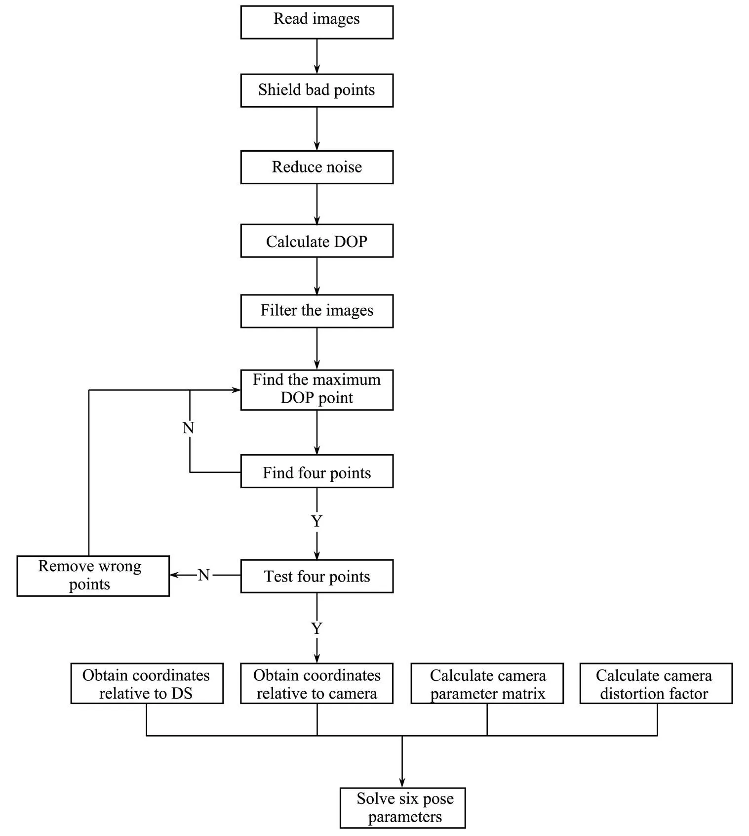
Fig.5 Flow chart of solution process for six pose parameters.

Fig.6 Schematic of the optics of the experiment.
3 Results and Discussion
In this section, we describe the simulations and experiments we conducted to illustrate the advantages of polarized versus unpolarized optical guidance. The quality of the DOP images was found to be better than the intensity images both above and under water, so we established that polarization imaging technology extends the operating distance of underwater optical guidance. To simulate the total pose errors of the proposed method, we obtained the pixel-recognition errors of the center of the AULs in the image and proved that underwater polarized optical guidance maintains the precision of traditional optical guidance. We conducted underwater experiments to evaluate the performance of the system and the feasibility of the proposed method.
3.1 Quality of Intensity and DOP Images
Fig.7 shows the intensity and DOP images of the atmosphericexperiment. At a distance of 5m, the AULs in the intensity image were barely visible, as depicted in Fig.7(a), whereas in the DOP image, they were clearly visible, as depicted in Fig.7(b). At a distance of 20m, the AULs in the intensity image were invisible, as shown in Fig.7(c), whereas in the DOP image, they were still visible, as shown in Fig.7(d). In the intensity images, the small red circles on the right enclose the light sources, and the big circles on the left are enlarged versions of the same. Table 1 shows the quality of the intensity and DOP images obtained in the atmosphericexperiment, which was calculated using Eq. (7). The above images were then simulated underwater, the quality of which are shown in Table 2. In Tables 1 and 2, we can see improvement with respect to the quality of the DOP images relative to intensity images. The image quality and improvement in Tables1 and 2, as obtained by Eq. (7), are dimensionless. These results establish that the quality of polarization imaging is obviously improved, especially under water and at a large distance. Thus, we have proved that polarization imaging technology hasa longer operating distance than traditional optical guidance technology.
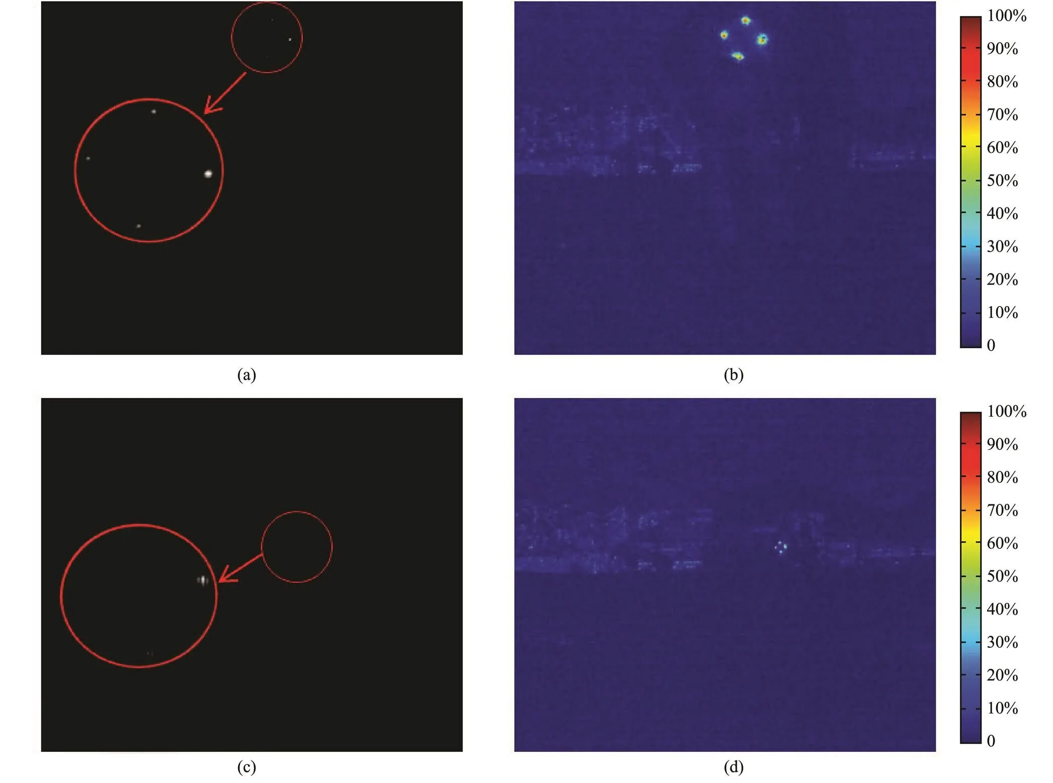
Fig.7 Atmospheric experiment. (a), intensity image at a distance of 5m; (b), DOP image at a distance of 5m; (c), intensity image at a distance of 20m; and (d), DOP image at a distance of 20m.

Table 1 Image quality of intensity and DOP above water

Table 2 Image quality of intensity and DOP under water
3.2 Precision of Polarized Optical Guidance
Using the algorithm, we calibrated the atmospheric images and obtained the pixel-recognition errors of the center of the AULs in the images. We acquired 10 images and obtained 40 pixel-recognition errors for every test position. We then calculated the mean errors, and Fig.8 shows the relationship between the distance and the error. At distances less than 3m and greater than 25m, the pixel errors are high due to overexposure and camera performance, respectively. This means the errors obtained at distances between 3m and 25m are valuable, which areshown in Fig.9. Next, we simulated the atmospheric images underwater and obtained the corresponding errors, which are also shown in Fig.9. Both these errors featured some distortion, but the underwater errors were the larger of the two. Owing to the scattering and absorption of particles in water, it is more difficult to recognize the center of the AUL underwater. We found the pixel-recognition error to be inversely proportional to the distance of the beacon from the camera. The closer was the beacon to the camera, the larger was the projected light in the image, which led to greater errors than those of beacons that were far away. These results are consistent with those reported in previous work (Vallicrosa, 2016). At the same time, if the light source had higher power or a bigger luminous area, the results would have been better at greater distances and worse at shorter distances due to overexposure and the large imaging area. In contrast, if the light source had lower power or a smaller luminous area, the camera would experience performance challenges at large distances.
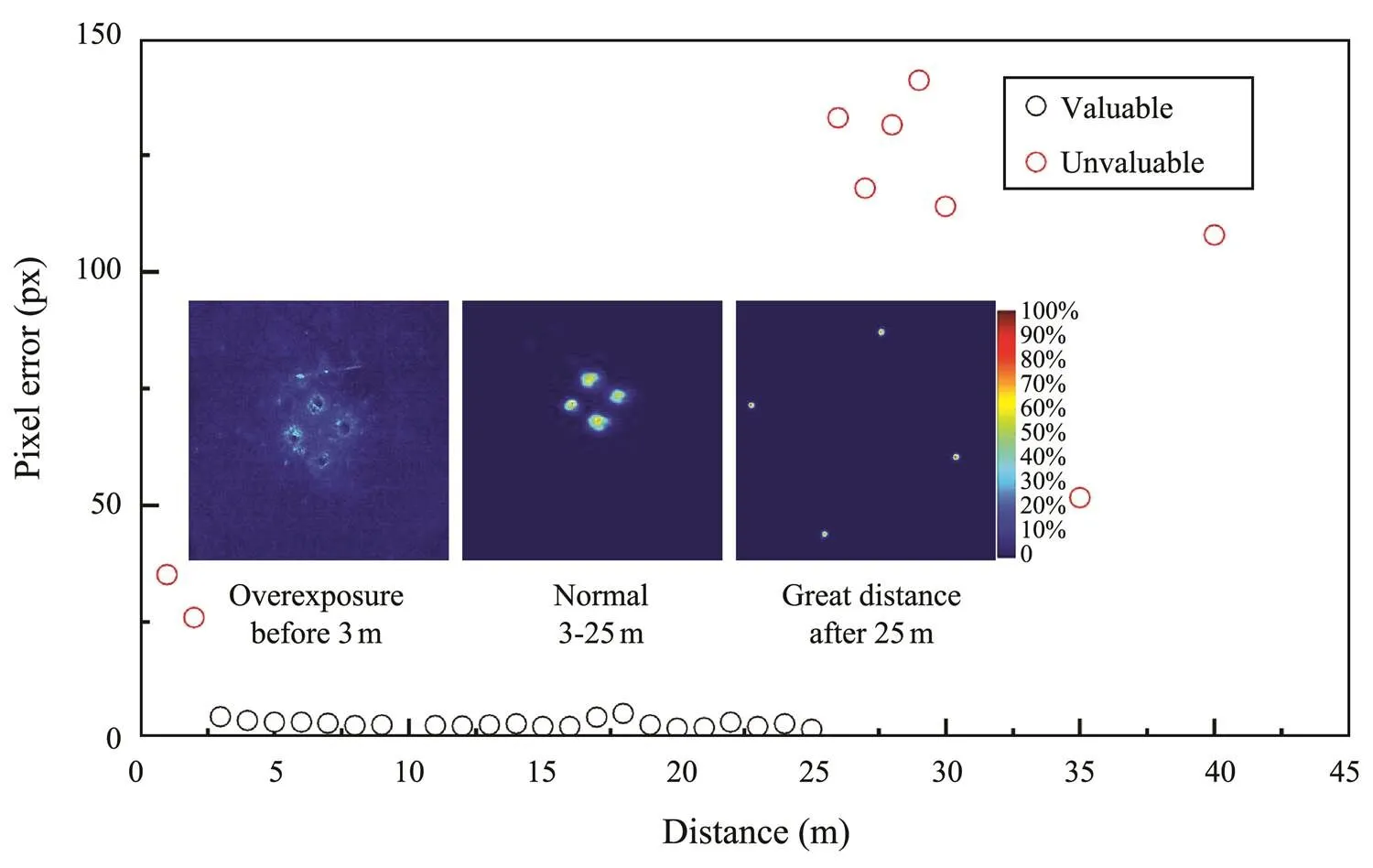
Fig.8 Mean pixel errors within 45m.
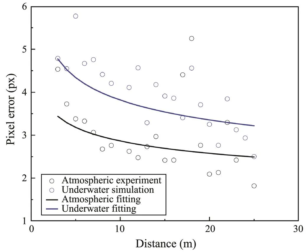
Fig.9 Pixel errors of atmospheric experiment and underwater simulation between 3 and 25m and their fitting results.
Fig.9 shows plots in which the atmospheric and underwater errors are fitted, wherein we can see that because of the water degradation, the pixel errors underwater were greater than those in the atmosphere. Lastly, after fitting the pixel errors at different distances, we input them into the AUV pose model to calculate the six parameters of the position and attitude. Due to the iterative nature of the algorithm, the angle and-direction distance errors were small. The total errors mainly depended on the distances along theanddirections. Fig.10 shows the simulation results of the relationship between the distance and the total errors of the AUV, in which we can see that the position errors of both the atmospheric and underwater images increased with the distance between the AUV and the DS. Within 100m, the atmospheric errors were no greater than 0.093m and the underwater errors were no greater than 0.116m. This degree of precision is consistent with the results obtained in previous work (Hong, 2003) using unpolarized optical guidance.
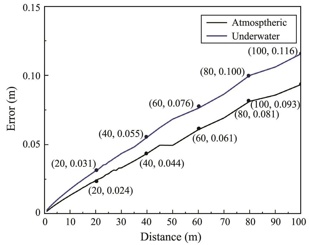
Fig.10 Total pose errors of the AUV within 100m.
3.3 Underwater Experiment
The underwater experiment was conducted in the coastal ocean in the afternoon to be consistent with the conditions used in the simulation. The underwater light field was polarized due to the refracted polarized skylight formedby the atmospheric scattering. However, the DOP of the underwater light field was significantly lower than that of the polarized AULs and had little impact on the experiment. Despite the absence of any interference from fish, seaweed, or other marine creatures, the underwater environment in the experiment was complex, much like the real AUV working environment. The water was semi-turbid and the visibility was poor owing to the absorption and scattering of light by various particles. Long-term underwater work would seriously shorten the life of the equipment because of seawater corrosion and pressure.The ocean waves, shoreline,seabed, and waterproof de-vice also had a negative influence on the experiment due to their impacts on the light. Except for the imaging method, the experimental conditions of the intensity and DOP images were the same. Fig.11 shows the intensity and DOP images of the polarized AULs in the underwater experiment, for which the distance between the beacon and the camera was 2m. In the intensity image, the light source was invisible, but its position is indicated by a red circle.In the DOP image, the light source was clear and successfully recognized, and the polarized AULs were four bright points that had higher DOP values than the background. The underwater DOP image had more noisy points owing to the scattering of various particles, and the calculation accuracy was poorer than the atmospheric image because of the complex underwater optical characteristics. There were also other bright points above the AULs that were darker than the polarized AULs, which were formed by the reflections of the water surface in the DOPimage. The total underwater pose error was 0.011m, which isconsistent with that of the simulation. This result verifies the superior performance of the proposed system and the feasibility of this method underwater.

Fig.11 Underwater experiment. (a) Intensity image and (b) DOP image.
4 Conclusions
In this paper, we proposed a real-time and bioinspired method that uses polarized optical guidance to determine the position and attitude of an AUV relative to a DS for homing and docking. This method, based on polarization imaging technology, extends the operating distance while maintaining the precision of traditional optical guidance. The simulation and experimental results obtained in this research serve as a feasibility study and provide the necessary evidence that such a method is warranted. The obtained angle errors were negligible, and the position errors were no greater than 0.116m within 100m in the coastal ocean. A fast calculation speed enables real-time solutions for the AUV position and attitude. Furthermore, this method is simple and inexpensive, requiring only the relative position of each AUL. Future work will focus on accelerating the calculation speed, developing a dynamic model, and conducting long-distance underwater experiments.
Acknowledgements
This work was supported by the National Natural Science Foundation of China (NSFC) (Nos. 51675076, 51505062), the Science Fund for Creative Research Groups of NSFC(No.51621064),and the Pre-Research Foundati on of China (No. 61405180102).
Cartron, L., Josef, N., Lerner, A., Mccusker, S. D., Darmaillacq, A. S., Dickel, L., and Shashar, N., 2013. Polarization vision can improve object detection in turbid waters by cuttlefish., 447 (3): 80-85.
Cheng, H. Y., Chu, J. K., Zhang, R., Tian, L. B., and Gui, X. Y., 2020. Underwater polarization patterns considering single Rayleigh scattering of water molecules., 41 (13): 4947-4962.
Cowen, S., Briest, S., and Dombrowski, J., 1997. Underwater docking of autonomous undersea vehicles using optical terminal guidance.. Halifax, 2: 1143-1147.
Deltheil, C., Didier, L., Hospital, E., and Brutzman, D. P., 2002. Simulating an optical guidance system for the recovery of an unmanned underwater vehicle., 25 (4): 568-574.
Dubreuil, M., Delrot, P., Leonard, I., Alfalou, A., Brosseau, C., and Dogariu, A., 2013. Exploring underwater target detection by imaging polarimetry and correlation techniques., 52 (5): 997-1005.
Fischler, M. A., and Bolles, R. C., 1987. Random sample consensus: A paradigm for model fitting with applications to image analysis and automated cartography., 24 (6), 381-395.
Hong, Y. H., Kim, J. Y., Lee, P. M., Jeon, B. H., Oh, K. H., and Oh, J. H., 2003. Development of the homing and docking algorithm for AUV.. Honolulu, 205-212.
Horváth, H. G., and Varjú, D., 2004.. Springer, Berlin, 470pp.
Hou, W., 2009. A simple underwater imaging model.,34 (17): 2688-2690.
Hufnagel, R. E., and Stanley, N. R., 1964. Modulation transfer function associated with image transmission through turbulent media., 54 (1): 52.
Kondo, H., Okayama, K., Choi, J. K., Hotta, T., Kondo, M., Okazaki, T., Singh, H., Chao, Z., Nitadori, K., Igarashi, M., and Fukuchi, T., 2012. Passive acoustic and optical guidance for underwater vehicles.. IEEE, Yeosu, 1: 1-6.
Lee, P. M., Jeon, B. H., and Kim, S. M., 2003. Visual servoing for underwater docking of an autonomous underwater vehicle with one camera.San Diego,2: 677-682.
Maki, T., Shiroku, R., Sato, Y., Matsuda, T., Sakamaki, T., and Ura, T., 2013. Docking method for hovering type AUVs by acoustic and visual positioning., Tokyo, 1-6.
Mobley, C. D., 1994.. Academic, San Diego, 592pp.
Park, J. Y., Jun, B. H., Lee, P. M., and Oh, J., 2009. Experiments on vision guided docking of an autonomous underwater vehicle using one camera., 36 (1): 48-61.
Petzold, T. J., 1972.. Scripps Institution of Oceanography La Jolla Ca Visibility Lab, La Jolla, 79pp.
Schechner, Y. Y., and Karpel, N., 2005. Recovery of underwater visibility and structure by polarization analysis., 30 (3): 570-587.
Schechner, Y. Y., Narasimhan, S. G., and Nayar, S. K., 2003. Polarization-based vision through haze., 42 (3): 511-525.
Shashar, N., Hagan, R., Boal, J. G., and Hanlon, R. T., 2000. Cuttlefish use polarization sensitivity in predation on silvery fish., 40 (1): 71-75.
Vallicrosa, G., Bosch, J., Palomeras, N., Ridao, P., Carreras, M., and Gracias, N., 2016. Autonomous homing and docking for AUVs using range-only localization and light beacons., 49 (23): 54-60.
Warrant, E. J., and Locket, N. A., 2004. Vision in the deep sea., 79 (3): 671-712.
Waterman, T. H., 2006. Reviving a neglected celestial underwater polarization compass for aquatic animals., 81 (1): 111-115.
Xu, Q., Guo, Z. Y., Tao, Q. Q., Jiao, W. Y., Wang, X. S., Qu, S. L., and Gao, J., 2015. Transmitting characteristics of polarization information under seawater., 54 (21): 6584.
Yahya, M. F., and Arshad, M. R., 2015. Tracking of multiple markers based on color for visual servo control in underwater docking..George Town, 482-487.
Yu, S. C., Ura, T., Fujii, T., and Kondo, H., 2001. Navigation of autonomous underwater vehicles based on artificial underwater landmarks.Honolulu, 1: 409-416.
. E-mail: chujk@dlut.edu.cn
December 8, 2019;
May 13, 2020;
May 18, 2020
(Edited by Xie Jun)
杂志排行
Journal of Ocean University of China的其它文章
- Phaeocystis globosa Bloom Monitoring: Based on P. globosa Induced Seawater Viscosity Modification Adjacent to a Nuclear Power Plant in Qinzhou Bay, China
- Effect of pH, Temperature, and CO2 Concentration on Growth and Lipid Accumulation of Nannochloropsis sp. MASCC 11
- Fuzzy Sliding Mode Active Disturbance Rejection Control of an Autonomous Underwater Vehicle-Manipulator System
- The 9–11 November 2013 Explosive Cyclone over the Japan Sea- Okhotsk Sea: Observations and WRF Modeling Analyses
- Characterization of the Complete Mitochondrial Genome of Arius dispar (Siluriformes: Ariidae) and Phylogenetic Analysis Among Sea Catfishes
- Establishment and Characterization of Four Long-Term Cultures of Neural Stem/Progenitor Cell Lines from the Japanese Flounder Paralichthys olivaceus
