Development of a low-loss magnetic-coupling pickup for 166.6-MHz quarter-wave beta = 1 superconducting cavities
2020-09-24TongMingHuangPeiZhangZhongQuanLiXinYingZhangHaiYingLinQiangMaFanBoMengWeiMinPan
Tong-Ming Huang· Pei Zhang· Zhong-Quan Li · Xin-Ying Zhang ·Hai-Ying Lin · Qiang Ma · Fan-Bo Meng · Wei-Min Pan
Abstract 166.6-MHz quarter-wave β=1 superconducting cavities have been adopted for the High Energy Photon Source, a 6-GeV diffraction-limited synchrotron light source currently under construction. A large helium jacket was required to accommodate the enlarged cavity beam pipe for the heavy damping of higher-order modes; the original electric-probe pickup thus becomes inevitably long with unfavorable mechanical properties. Relocated to an existing high-pressure-rinsing port,a magnetic-loop pickup was designed, characterized by low radio-frequency and cryogenic losses and being multipacting-free and insensitive to manufacturing and assembly tolerances. The consequent removal of the original pickup port from the cavity largely simplified the helium jacket fabrication and may also reduce cavity contamination. This paper presents a comprehensive design of a low-loss magnetic-coupling pickup for quarter-wave β=1 superconducting cavities.The design can also be applied to other non-elliptical structures.
Keywords Pickup · Magnetic coupling · Quarter-wave cavity · Superconducting cavity · Low loss · Synchrotron light source
1 Introduction
High Energy Photon Source (HEPS) is a 6-GeV diffraction-limited synchrotron light source with a kilometer-scale storage ring [1–3]. The project is currently under construction in a Beijing suburb and will be completed in 2025. The fundamental radio-frequency (RF)system is of 166.6-MHz, adopting superconducting technologies [4].During the R&D phase of HEPS [5],a proofof-principle (PoP) 166.6-MHz superconducting quarterwave β=1 cavity was developed with excellent RF and mechanical performances [6–8].
Based on the success of the PoP cavity as shown in Fig. 1a, a higher-order mode (HOM)-damped 166.6-MHz cavity was subsequently designed. The cavity beam pipe was enlarged to 500 mm in diameter to realize strong HOM damping with a required loaded quality factor (QL) of merely a few hundreds. The corresponding helium jacket became consequently larger with an increased diameter from 485 mm to 576 mm as shown in Fig. 1b. This,however, makes the original electric-probe pickup inevitably long which may undermine its mechanical properties.In addition, the original manufacturing techniques for the helium jacket become prohibitively challenging by welding two half vessels together with the cavity. Therefore, a simplified helium jacket design was highly desired. The pickup was finally relocated to one of the existing highpressure rinsing (HPR) ports on the cavity end plate as shown in Fig. 1c, while the original pickup port was completely eliminated.Positioned at the‘‘short end’’of the quarter-wave cavity, magnetic, rather than electric, coupling was conceived for the pickup.
For non-elliptical superconducting cavities such as quarter-wave resonators (QWRs), half-wave resonators(HWRs),and spoke resonators,both the electric probe and magnetic loop are the two conventional structures for pickups. The former is often positioned on the cavity side wall, while the latter is on the end plate. Electric-probe pickups are usually arranged on the opposite side of the fundamental power coupler (FPC) to alleviate potential coupler kick effect by restoring the electromagnetic field symmetries [9, 10]. The 80.5-MHz QWRs for FRIB at MSU [11],162.5-MHz HWRs for CADS at IMP [12],and 325-MHz spoke resonators for PIP-II at Fermilab [13] are among those who adopted pickups of the electric-probe type. On the other hand, cavities with existing HPR ports and negligible coupler kicks could use magnetic-loop pickups. The 176-MHz HWRs for SARAF at SNRC [14],56-MHz β=1 QWRs for RHIC at BNL [15, 16] and 162.5-MHz HWRs for PIP-II at Fermilab [17] are a few examples. In the case of 166.6-MHz β=1 quarter-wave cavities for HEPS, coupler kicks were undiscoverable thanks to a careful selection of the FPC’s location [18] as shown in Fig. 1. Therefore, a magnetic-loop-type pickup mounted on an existing HPR port was chosen. Fabrication of the helium jacket was thus largely simplified, while a cavity geometry with fewer ports was also favored and may reduce cavity contaminations.
This paper presents the design and the prototyping of a magnetic-loop pickup for the 166.6-MHz HOM-damped quarter-wave β=1 superconducting cavity. Simple structure, robust design, and low cryogenic loss are the main focus of this study.This paper is organized as follows.The design of the pickup is presented in Sect. 2 with elaborations on coupling,multipacting,and thermal optimizations.A pickup prototype was subsequently fabricated to validate the design and to examine manufacturing feasibilities.Measurements and comparison to simulation results are shown in Sect. 3.
2 Design
A pickup is an essential ancillary for RF cavities. It extracts a small amount of cavity stored energy that is proportional to the electromagnetic field level inside the resonator. In order to minimize its effect, the pickup is often very weakly coupled to the cavity with a typical external quality factor, Qext, larger than 1010. The specifications of the pickup for HEPS 166.6 MHz cavities are listed in Table 1.The cryogenic heat load at 4.2 K has to be carefully controlled to be less than 1 W at a cavity operating voltage of 1.2 MV.
A magnetic coupling pickup was designed and located on one existing HPR port for the 166.6-MHz HOMdamped cavity.Focusing on low RF loss and low cryogenic heat load, multipacting free, and insensitive to manufacturing and assembly tolerances, a comprehensive design consisting of RF coupling, multipacting, and thermal optimization is presented in this section.In order to reserve some design margin, the optimization was conducted at a designed cavity voltage of 1.5 MV.
Although the pin-type pickup located at the cavity main body as shown in Fig. 1b was abandoned at the first place,its RF and thermal properties have nevertheless been evaluated for the sake of completeness. The results are presented in Fig. 2a and Table 2. The simulations were conducted by using ANSYS software suite[19].All pickup tips will be made of oxygen-free high thermal conductivity(OFHC) copper. Located at the ‘‘short end’’ of the cavity where the magnetic field dominates, a hook-like structure was conceived in order to increase magnetic coupling strength as shown in Fig. 2b. Comparing to the original electric-probe pickup (Fig. 2a), the required coupling of 5×10¹⁰was achieved by a slightly deeper insertion of the hook into the cavity port as listed in Table 2.However,RF loss on the hook was calculated to be almost 1 W that is ten times higher than that on the electric probe.It consequently caused an overheating of the NbTi flange reaching 12.2 K,exceeding its superconducting critical temperature at a designed cavity field of 1.5 MV, and adding an unacceptable heat load of 1.9 W to the total cavity cryogenic loss.
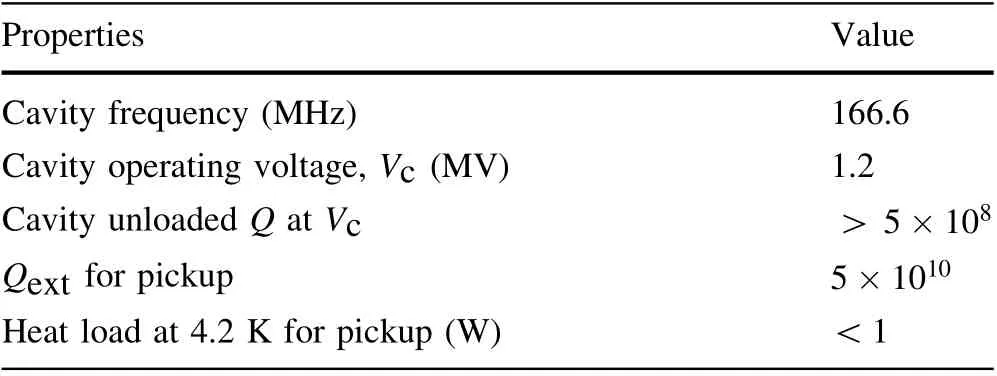
Table 1 Specifications of the pickup for HEPS 166.6-MHz cavities
The undesirably high RF loss on the pickup can be reduced by extracting the hook from the cavity port to lower its surface magnetic field as shown in Fig. 2c. In order to further increase the coupling strength to fulfill the required Qext,the inner conductor and the outer conductor of the pickup were physically connected to form a loop.The pickup was retreated out of the cavity port leading to a considerable reduction of surface magnetic field on the loop. The heat loss on the pickup at the retracted location has dropped to 4.6 mW. The previous overheating on the flange was consequently alleviated, and the temperatures on the pickup inner conductor and the niobium port tube were also lowered. A cryogenic heat load of 0.5 W was finally achieved, fulfilling the specification. These are listed in Table 2. Temperatures on the inner conductor and the niobium port tube were also decreased.This design was inspired by a previous work conducted at BNL for the RHIC 56 MHz β=1 QWR [15]. Unlike the BNL case,where the pickup and the power coupler share a similar structure for engineering convenience, our design was noticeably simplified due to its sole function as a pickup.
2.1 Coupling
The coupling strength of the pickup was calculated by using CST Microwave Studio [20]. The pickup insertion,h, is defined in Fig. 3 where a negative value represents a pickup retracted from the cavity volume into the port tube extension, while the angle measures the relative rotation between the loop and the cavity. Qext was proportional to the pickup insertion in a logarithm manner as shown in Fig. 4a. The magnetic field lines passing through the loop cross section are proportional to the loop rotation angle where 0°represents a maximum magnetic flux thus giving a strongest coupling,while 90°presents almost no coupling as shown in Fig. 4b. In order to minimize the insertion depth,therefore lowering the RF loss,the angle of 0°offers a strongest coupling and was chosen with an insertion depth of - 64 mm.
The coupling strength may be affected by the manufacturing and assembly tolerances.Qext will change 17.0%by an insertion deviation of 1 mm and 6.7%by as large as a 15°angle rotation. In addition, the pickup may be offset from the flange center in the vertical plane as shown in Fig. 3c.Qext will increase by 4%with a 3-mm offset in the V axis and 8%in the U axis as shown in Fig. 5.The pickup is not sensitive to tolerances.
2.2 Multipacting
Multipacting is an undesired phenomenon of resonant electrons avalanching inside the evacuated RF structures,in which a large number of electrons build up, absorb RF power, and impact the structure’s walls, leading to remarkable power losses and wall heating [21].In the case of superconducting cavities in particular,the bombardment of these electrons may cause thermal breakdowns. Multipacting occurs when electrons return to the RF surface after an integer number of RF cycles, thus forming resonant trajectories, and deposit energies to the walls where the secondary emission coefficient (SEC) of the material is greater than one. The former is determined by the electromagnetic field at a given RF geometry, while the latter depends on the material and its surface quality. Soft multipacting barriers are those that could be processed,and are thus highly dependent on surface conditions, while hard barriers are the persistent ones that can often be attributed to ‘‘unfavored’’ geometries [22]. In the design phase, it is important to optimize the RF geometry to remove the hard multipacting barriers and to check the soft multipacting band that may exist on an unsatisfactory surface condition.This is particularly crucial for magnetic coupling structures located at the cavity ‘‘short end’’ where high risk of multipacting was demonstrated due to intensive cavity magnetic field [6].
Multipacting of the magnetic-coupling loop pickup was analyzed by using CST Microwave Studio and Particle Studio [20]. In order to obtain a precise positioning of the multipacting, the pickup was divided into three regions as shown in Fig. 6: niobium tube, pickup loop, and coaxial section.The SEC curves of materials used in the simulation are from the material library of CST Studio Suite as shown in Fig. 7. For the niobium tube, baked niobium was initially used.Initial particles with a kinetic energy between 0 and 4 eV were emitted from the RF surface of each region at a random angle. Then, the trajectories and energies of the particles were tracked over predefined field levels and RF phases for a minimum of 20 RF cycles.The probability of multipacting occurrence was characterized by a normalized SEY,<SEY>, which is defined as the ratio of the total number of secondary electrons to the total number of impacts [23]. Multipacting may occur when <SEY>exceeds one. The results are shown in Fig. 8. One multipacting band can be observed between 0.3 and 0.8 MV when initial electrons were launched from the surface of the niobium tube.This turned out to be a soft barrier,as the<SEY>values decreased drastically with a less emitting material. From its resonant trajectories shown in Fig. 9,this MP is located at the end plate and was predicted in previous studies [6]. The pickup itself has no observed multipacting.
2.3 Thermal
Mounted on the superconducting cavity at one end and connected to the feedthrough on the cryomodule at the other end, pickup acts as a thermal bridge between the cryogenic temperature and the room temperature, thus contributing to the total cavity cryogenic heat loss.The RF loss on various pickup components was calculated by using CST and HFSS software as listed in Table 3. A total RF loss at room temperature (300 K) of less than 6 mW was obtained at a cavity voltage of 1.5 MV.

Table 3 RF loss at room temperature (300 K) on each component from CST and HFSS [19] simulations
A multiphysics analysis consisting of coupled simulations of RF and steady-state thermal was conducted by using the ANSYS software suite. Considering that both electrical and thermal conductivities are temperature dependent, a two-way iterated RF–thermal-coupled simulation was carried out as shown in Fig. 10. RF losses at room temperature were initially calculated and loaded into the thermal simulation. The resulting temperature distribution was then fed back to the RF simulation to update the temperature-dependent electrical conductivities. RF losses were subsequently recalculated. The RF–thermal iteration stops when the variation of the heat load at 4.2 K is below 10%. At this point, the coupled simulation is complete.
The model and its conditions for simulations are shown in Fig. 11.The pickup assembly consists of the pickup and its associated flange, the feedthrough, and the cable.Immersed in the liquid helium, the temperature of the niobium tube and the NbTi flange within the helium jacket envelop was set to 4.2 K, while the other end of the cable outside the cryomodule was set to 298 K. The rest of the pickup assembly was under an isolation vacuum inside the cryomodule.
A popular cable assembly of 500 mm long with an outer diameter of 5.5 mm for the jacket, denoted as D5.5-L500,was initially chosen for the pickup.Simulations predicted a 1.3 W heat load at 4.2 K, exceeding the required value as listed in Table 4.Due to a negligible RF loss on the pickup,the dominant loss mechanism is static heat load conducted from the room-temperature end. Therefore, a longer cable will help reduce heat loss at the cold end. A value of 0.77 W was achieved by simply doubling the cable length to 1000 mm.Another remedy will be to add a thermal anchor along the cable to intercept the heat from the room-temperature end. The position of the thermal anchor has been varied to examine its effect on heat load at 4.2 K as shown in Fig. 12. The value can be reduced to 0.75 W with a proper selection of the anchor position. However, the risk of condensation and the special requirements to thermally bridge the inner and outer conductor of the cable make this approach less attractive.Finally,a thinner and longer cable,D4.1-L1000,was chosen with a calculated heat load of 0.5 W at 4.2 K while preserving sufficient mechanical rigidity.The temperature distribution using this cable setup is shown in Fig. 13. Temperature readouts on both the niobium tube and the NbTi flange are far below the superconducting critical temperature of niobium (9.25 K) and the NbTi alloy (~10 K).
3 Prototyping and tests
In order to validate the design, a prototype loop pickup was fabricated as shown in Fig. 14a. It consists of three individual parts:a copper pickup tip,a stainless-steel flange with an outer conductor, and an off-the-shelf feedthrough.The pickup tip was connected to the inner conductor of the feedthrough by a screw thread and soldered with the outer conductor by a silver copper alloy. The feedthrough was joined with the flange through tungsten inert gas (TIG)welding.
The pickup was subsequently mounted on the PoP cavity to measure its coupling strength as shown in Fig. 14b. Compared to the low unloaded quality factor of the cavity at room temperature, the pickup was highly under-coupled; thus, its Qext was measured by using the two-port method described in [24]. One antenna pin with strong coupling (Qext =2×10⁴) was installed on the power coupler port to drive the cavity.The pickup insertion h was varied by using different gaskets of various thicknesses. The measurement and simulation are in goodagreement as shown in Fig. 15. A 12% higher Qext was obtained, corresponding to a less than 1-mm insertion deviation. Although a visible deformation of the loop tip was observed due to soldering at high temperature, the pickup coupling strength did not change much, proving its insensitivity to tolerances.
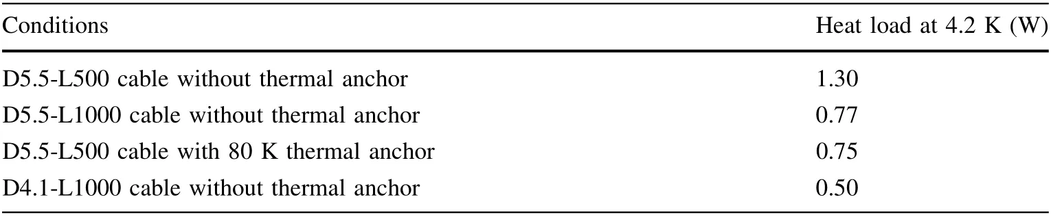
Table 4 Simulated heat load at 4.2 K with different cables under different conditions
4 Final remarks
A low-loss magnetic-coupling pickup was designed for the HOM-damped 166.6-MHz quarter-wave β=1 superconducting cavity.Positioned on an existing high-pressurerinsing port on the end plate,the helium jacket was largely simplified, in addition to the removal of one port from the cavity. The pickup features a low RF loss by an optimized loop structure and a low cryogenic heat load by an extended cable with smaller diameter. A thorough coupled simulation was conducted. Multipacting was analyzed and no hard barriers were observed. A prototype pickup was subsequently fabricated and tested on the existing cavity.The measurements were consistent with simulation predictions. The design can also be applied to other non-elliptical superconducting cavities with an existing rinsing port.
AcknowlegementsThis work was supported by High Energy Photon Source (HEPS) project, a major national science and technology infrastructure.Funding was also received from the Chinese Academy of Sciences.
杂志排行

Nuclear Science and Techniques的其它文章
- Digitalization of inverting filter shaping circuit for nuclear pulse signals
- Scheme for generating 1 nm X-ray beams carrying orbital angular momentum at the SXFEL
- Investigating the effect of entrance channel mass asymmetry on fusion reactions using the Skyrme energy density formalism
- High-precision and wide-range real-time neutron flux monitor system through multipoint linear calibration
- Correction to: Theoretical prediction of radiation-enhanced diffusion behavior in nickel under self-ion irradiation
- Preparation of large-area isotopic magnesium targets for the 25Mg(p,γ)26Al experiment at JUNA