Discharge instability in a plasma contactor
2020-09-14
School of Aerospace Engineering,Beijing Institute of Technology,Beijing 100081,People’s Republic of China
Abstract
Keywords:plasma contactor,discharge instability,emission characteristics
1.Introduction
As a plasma source,by spraying plasma to the space environment,a hollow cathode plasma contactor(HCPC)can establish a current loop with the space plasma.To date,HCPC has been used in the fields of spacecraft surface potential active control[1-8]and electrodynamic tether technology[9-14].When used as an electron emitter,electrons will transfer along the following path:(1) external circuit;(2) cathode tube;(3) electron emitter;(4)plasma in the emitter region;(5)plasma in the hollow region;(6) plasma jet;(7) space plasma.The potential difference between the space plasma and the contactor is the anode voltage,and the electron current emitted by the contactor to the external environment is the anode current.The relationship between the two is the emission characteristic of the plasma contactor,which is the key performance parameter in a space mission.A high anode voltage will lead to oscillation,which will affect the contactor’s control of the floating potential of the structure[15-18].However,there are few reports detailing the instability of the plasma contactor.Because the core of the component is a hollow cathode,and the unstable discharge situation of the plasma contactor is similar to that of the hollow cathode[18-21],scholars have studied the oscillation of plasma contactors by studying the discharge instability of hollow cathodes.
The hollow cathode is an efficient indirectly heated cathode.The amplitude and frequency of the pulses vary with different space positions and discharge conditions during the hollow cathode discharge process.Goebel proposed a direct current potential mountain model and an explanation of ion acoustic wave instability,but the simulation results were quite different from the experimental results.Then Goebel discovered that there were two discharge modes,one point-like,the other feather-like,in the arc phase.The transition between the two modes will increase the plasma density and voltage amplitude,which will cause severe corrosion of the hollow cathode [22-24].
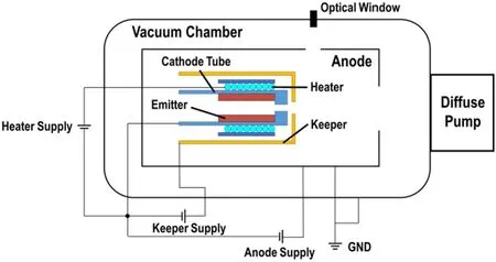
Figure 1.Schematic diagram of HCPC system.
Much research has also been conducted on the instability of high-current discharge.Williams and Farnell from the University of Colorado established a probe system for the measurement of the hollow cathode space potential under different anode conditions.It was found that there were still obvious discharge pulses,which indicated that the discharge pulses have little relation with the anode conditions.At the same time,they also measured microscopic quantities such as plasma density and electron temperature.Based on the experimental results,Williams and Farnell proposed an ion transport model [25].Through experimental research,Grubisic et al from the University of Southampton in the UK found that the hollow cathode discharge pulse and the entire use and replenishment of neutral gas were linked [26].Dodson et al[27]from the University of California measured the ion velocity in the axial and radial directions of the hollow cathode plume region.It was found that the direction of ion acoustic wave propagation was from the cathode hole outward along the direction of ion migration.Sakai et al [28]from Tokyo Metropolitan University investigated discharge pulse oscillation by studying the three types of hollow cathode discharges (feather,dot,and diffuse modes),and found that the discharge current pulse was affected by the shape of the hollow cathode discharge.Yanes et al [29]from California Institute of Technology studied the potential pulse caused by ion acoustic waves in the hollow cathode discharge of a Hall-effect engine.The existence of ion acoustic waves in a large current hollow cathode was confirmed in experiments.This may explain the existence of high-energy ions.It was found that the hollow cathode showed potential pulse oscillations in different discharge structures.The potential pulse oscillation should be universal.
Since the hollow cathode is the core part of a plasma contactor,it can be speculated that the plasma contactor will also be subject to instability during the discharge process.At present,there are few studies on the instability of plasma contactors,and most of them focus on the emission characteristics of contactors [30].
In the present work,an experimental investigation into the discharge instability of the plasma contactor was performed.The experimental results show that the discharge oscillation of the plasma contactor is not exactly the same as the discharge oscillation of the hollow cathode.The discharge instability of the hollow cathode is mainly related to the ratio of the anode current to gas flow,and the oscillation of the contactor depends mainly on the anode current[19].The discharge parameters of the oscillation phase,the frequency,and amplitude of the main peak under different operating conditions were measured in these experiments,and then the instability performance of the plasma contactor discharge was assessed.
2.Experimental set-up
The HCPC system is shown in figure 1.The vacuum chamber is made of stainless steel with a diameter of 1.8 m and a total length of 4 m.The pumping speed of the diffusion pump is 5×10⁵m s-1.The ultimate vacuum degree in the chamber is 5×10⁻⁴Pa.During the measurement,the vacuum cabin pressure was 8×10⁻⁴-3×10⁻³Pa.The flow rate of xenon gas was controlled by the thermal flowmeter,the control range was 0-20 sccm,the control accuracy was ±1%,the measurement accuracy was ±1%,and the display accuracy was 0.01 sccm.
The HCPC system used in the experiment mainly includes a plasma contactor and a simulated anode.The outer diameter of the cathode tube is 6 mm,the diameter of the cathode hole is 0.6 mm,the diameter of the keeper hole is 3.6 mm,and the distance between keeper and cathode is 1 mm.The vacuum contactor is usually used as the anode in the ground test of the plasma contactor [31,32],but in this study,a simulated anode is used based on the requirement.The simulated anode is an 800×800×1400 mm3anode compartment made of stainless steel.The high-vacuum pump is a diffusion pump,and there will be a significant oil return after long-term operation.Degreasing a large area of the wall cannot guarantee the quality of the wall surface,so the emission characteristics and plasma jet structure may be greatly disturbed.It can be removed and unified for degreasing after each test to ensure repeatability of the test results.
In measurements,two current probes(TCP0030A)and two voltage probes (TPP0250) were connected to the oscilloscope for measurement.The oscilloscope (TeckMDO3014,measurement accuracy ±1%) was used to simultaneously measure the anode voltage,the anode current,the keeper voltage,and the keeper current waveform.The measurement was performed at a sampling rate of 100 MHz.The camera was used to observe the discharge plume of the contactor through the optical window.Since we only needed to do a simple analysis of the discharge,no filter was used.
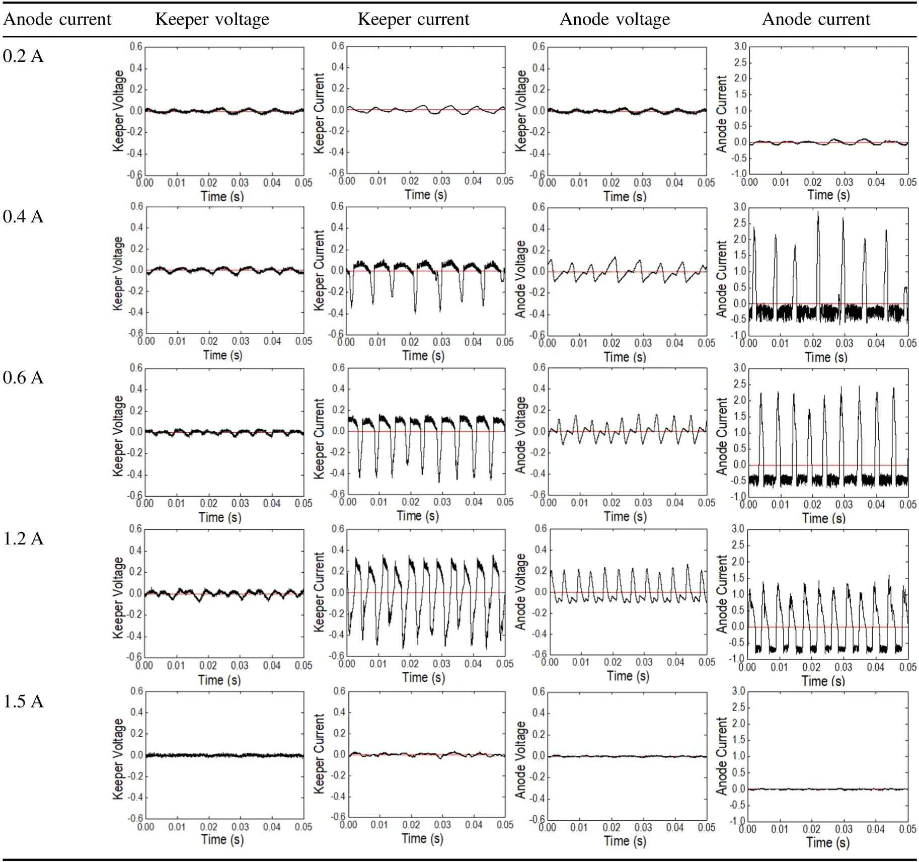
Table 1.Relative fluctuations of each parameter.
3.Results and discussion
The emission characteristic curve of the plasma contactor shown in figure 2 includes three stages.In the first stage,the anode voltage linearly increases with the anode current.In the second stage,the anode voltage decreases with the increase of the anode current.In the third stage,as the anode current further increases,the discharge gradually enters a stable state.It can be seen from table 1 that the area within the bulge in the anode voltage curve is almost the same as the discharge unstable area,so this is our focus.
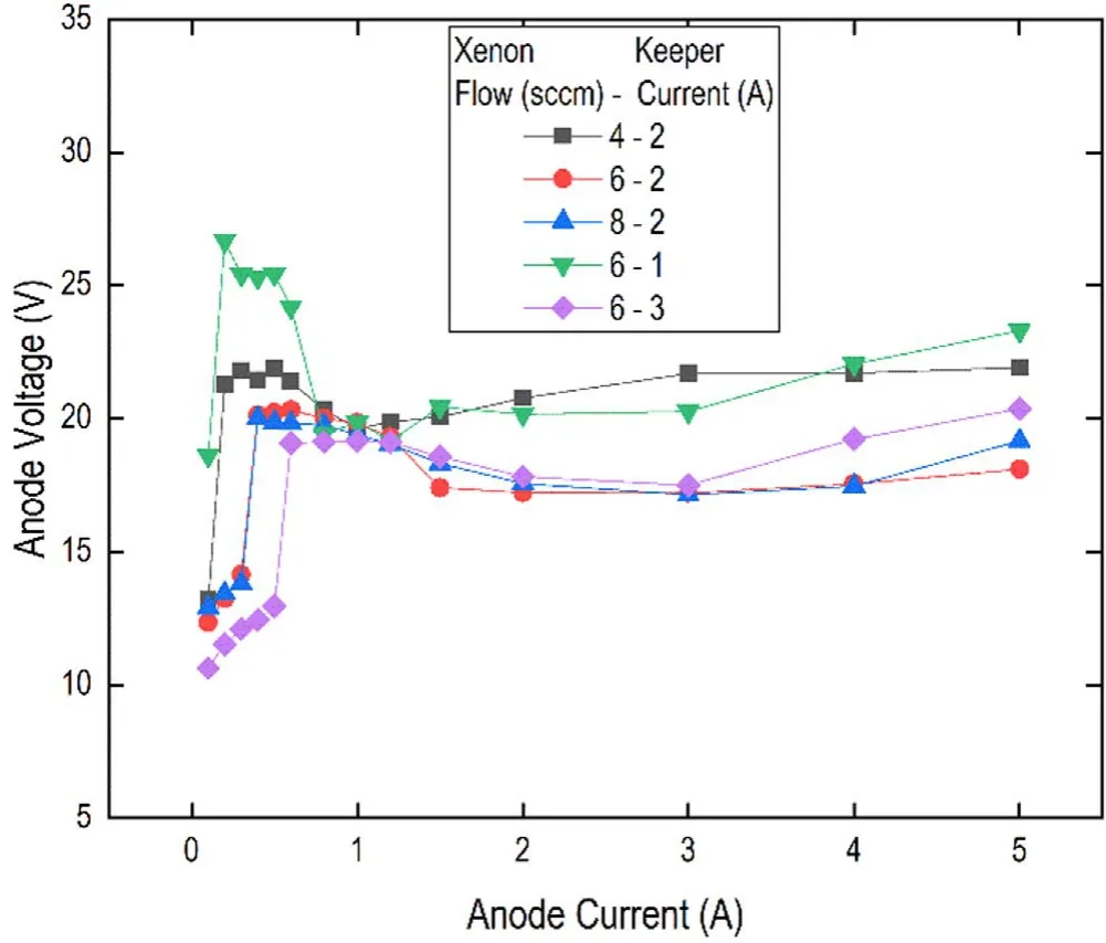
Figure 2.Emission characteristics of contactors under different working conditions.
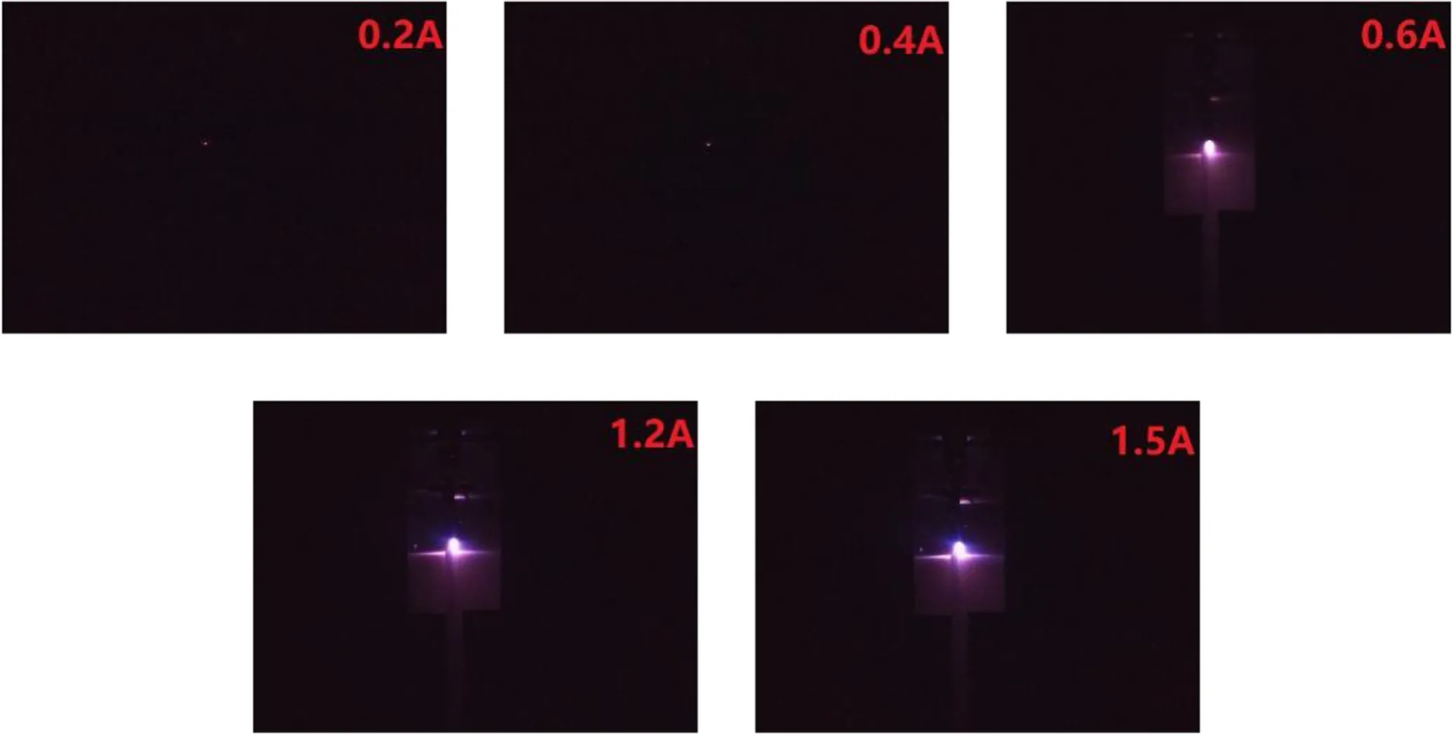
Figure 3.Discharge situations under different anode currents.
In this experiment,the gas flow conditions were 4,6,8 sccm,and the contact current conditions were 1,2,3 A.We took the average condition as the typical condition for the further study.Table 1 lists the experimental results under conditions of a 6 sccm xenon flow and a 2 A keeper current.Dimensionless processing was conducted on the experimental results according to equation (1):
In general,the discharge instability of the plasma contactor is mainly reflected in the current,and the oscillation of the anode current is greatest;therefore,the discharge instability is defined according to the oscillation of the anode current:when the relative oscillation amplitude is greater than±10%,the contactor is considered unstable.Although there are oscillations when the anode current is 0.2 A or 1.5 A,their oscillation amplitude is relatively small,so it is not considered to be in an unstable state.
When the anode current is 0.2 A,the contactor discharge is stable.When the anode current reaches 0.4 A,the contactor begins to discharge in an unstable manner.The four parameters begin oscillating significantly.When the current further increases by 1.5 A,the contactor discharges back to steady state.In the oscillating region,the oscillation of the anode current is most obvious,and the relative oscillation amplitude can reach nearly 200%.The basic oscillating waveform of the anode current is composed of two waveforms with different characteristics:a positive large-amplitude,low-frequency wave and a negative small-amplitude,high-frequency wave.The low-frequency wave oscillation interval includes areas less than and greater than the average value,and the amplitude is similar to the amplitude of the entire wave;the high-frequency wave oscillation interval is only the area less than the average value,and the relative amplitude is small,at only 10%.In the second stage,the characteristics of low-frequency waves can be approximated by triangular waves.The current rapidly rises to the maximum and decreases to the minimum at the same rate,and the oscillation waveform tends to stabilise;the characteristics of high-frequency waves can be approximated by sawtooth waves:the start and end points respectively correspond to the end and start points of the low-frequency wave.With the increase of the anode current,the relative oscillation amplitude of low-frequency waves gradually decreases,the frequency gradually increases,and the proportion of relatively high-frequency waves gradually increases.Compared with the anode current,the keeper current waveform is composed of a negative large-amplitude,low-frequency triangular wave and a positive small-amplitude,high-frequency sawtooth wave.The low-and high-frequency oscillation characteristics of the keeper current are akin to the low-and high-frequency oscillation characteristics of the anode current.Compared with the current oscillation,the keeper voltage and the anode voltage have a relatively small amplitude in the second stage.The entire waveform of the keeper voltage oscillation can be approximated by a sawtooth wave,and the entire waveform of the anode voltage oscillation can be approximated by a triangular wave.The oscillation of the anode voltage is greater than that of the keeper voltage.
Figure 3 shows the discharge situations under different anode currents at 6 sccm and 2 A.Experiments show that when the contactor changes from a stable state of discharge to an unstable boundary,the shape of the discharge changes to a significant extent.In the stable stage,the plume contains only one bright spot,and in the unstable stage,the plume shape transition is similar to the discharge shape transition that occurs when the hollow cathode discharge is unstable [33].
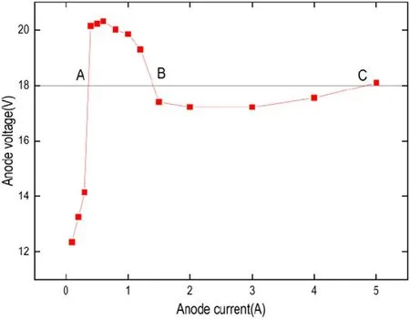
Figure 4.Emission characteristic curve of 6 sccm,2 A contactor.
From the anode current oscillation waveform,the positive amplitude of the low-frequency wave is much larger than the negative amplitude of the high-frequency wave (this can be explained by the emission characteristic curve).Figure 4 demonstrates the emission characteristic curve corresponding to working conditions such that the gas flow rate is 6 sccm and the keeper current is 2 A.The anode voltage in the oscillation region generally corresponds to multiple anode currents.As shown in figure 4,the straight line and the emission characteristic curve intersect at three points:A,B,and C.It is assumed that when oscillation occurs at point A,it will oscillate around the same anode voltage;therefore,if it oscillates in the direction of the decreasing anode current,it will quickly enter the stable region,quickly returning to oscillation point A,so the frequency is high and the interval between oscillations is small.If the anode current oscillates in the direction of increasing current,it will oscillate between A-B and even B-C,so the frequency is low and the oscillation period is longer;therefore,the instability of the discharge causes the anode voltage curve to bulge in terms of its emission characteristics,so the emission characteristics make the waveform of the anode current more special.
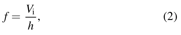
Figure 5 shows the relative waveforms of the instantaneous keeper current,keeper voltage,anode current,and anode voltage at a gas flow of 6 sccm,a keeper current of 2 A,and anode currents of 0.4 A (a) and 0.8 A (b).andin the figures,which are the actual amplitude divided by the average value,refer to the relative amplitudes of voltage and current,respectively.The phases of anode voltage and anode current are similar;the anode voltage will reach a maximum before the current,then they reach their respective minima simultaneously.The phases of the keeper voltage and the keeper current are also similar.The keeper voltage is reduced to a minimum before the keeper current.When the keeper voltage reaches a minimum,the keeper current starts to decrease.As shown in figure 5,the phase of the keeper voltage current is opposite to that of the anode voltage current.
Figure 6 shows a fast Fourier analysis of the amplitudefrequency characteristics of the anode current waveform in the oscillating region at a flow rate of 6 sccm and a keeper current of 2 A.As in fgiure 5,is the relative current amplitude,which is the actual amplitude of the parameter divided by the average value.According to the magnitude of the oscillation amplitude,the peak with the largest amplitude is called the main peak,and the remaining peaks are called the second peak and third peak in turn.The main peak shows hundreds of Hz in oscillation frequency,so this pulse can be considered as an ionising pulse.Assuming that the ion velocity is about 300 ms−1and the closest distance between the cathode and anode is 0.4 m in the radial direction,and according to equation(2),we can simply estimate the value of the oscillation frequency,
whereViis the ion velocity,andhis the closest distance between the cathode and anode.
The calculation shows that the oscillation frequency is about 750 Hz,which is consistent with the measurement results in terms of their order of magnitude.It can be speculated that this oscillation is mainly due to the selfexcited oscillation of the contactor rather than the power circuit structure.
In table 2,when the flow of xenon gas is 6 sccm and the keeper current is 2 A,we give the relative amplitude-frequency characteristic data of different anode currents in the oscillation region.It can be seen from the table that with the change of the anode current,the amplitude and frequency of the main peak follow certain trends:when the anode current increases,the frequency of the main peak,second peak,and third peak and amplitude of the main peak will increase as the anode current increases.When the keeper current,gas flow rate,and anode current are all constants,the frequency increases with the decrease of the oscillation amplitude.
Figure 7 shows the frequency and amplitude characteristics of the main peak of the anode current oscillation under different operating conditions.Figure 7(a)shows the frequency and amplitude change of the corresponding main peak when the keeper current is 2 A.The main peak amplitude of the anode current oscillation under different xenon flow rates is obvious.As the anode current increases,the amplitude of the main peak of the anode current increases.As the anode current changes,the frequency characteristics of the main peaks become complicated,but overall each parameter shows hundreds of Hz.When the gas flow rate is 4 sccm,the frequency of the main peak decreases with the increase of the anode current.When the gas flow rates are 6 and 8 sccm,the corresponding frequency of the main peak is similar,albeit smaller overall compared with that at a gas flow of 4 sccm.Figure 7(b)illustrates the frequency and amplitude change of the corresponding main peak at different keeper currents when the gas flow rate is 6 sccm.It can be seen from the figure that the amplitude and frequency of the main peak of the anode current oscillation under different holding currents become complicated and change under different working conditions.When the keeper current is 1 A,the frequency of the peak decreases as the anode current decreases.The amplitude of the main peak is small under different anode currents;when the keeper current is 2 A or 3 A,the frequency and amplitude of the peak increase with increasing anode current.
Figure 5.Phase analysis of the oscillation waveform.
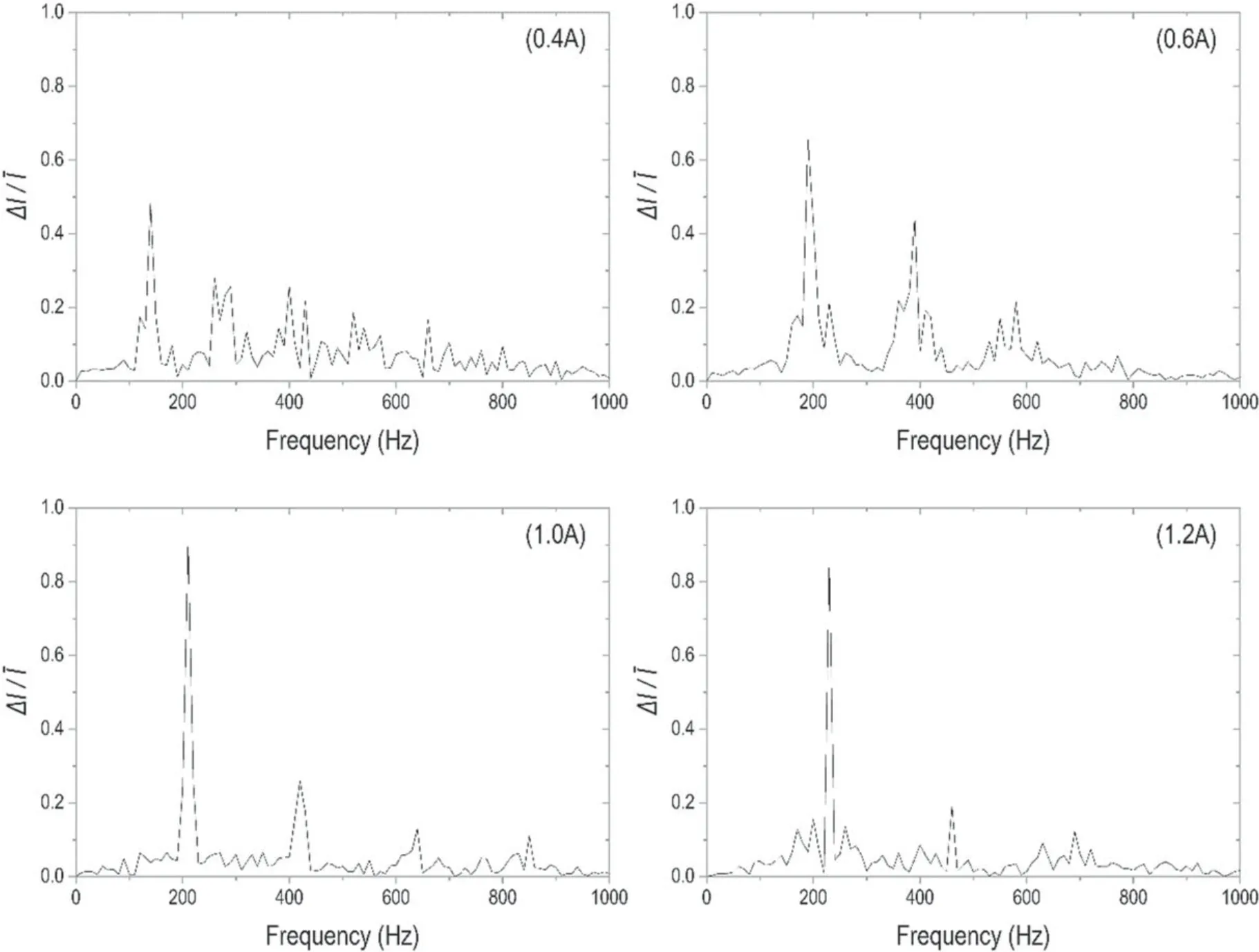
Figure 6.Amplitude and frequency analysis of anode current in oscillation region.
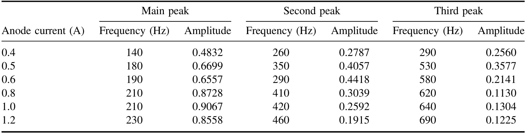
Table 2.Oscillation frequency and amplitude at different anode current nodes.
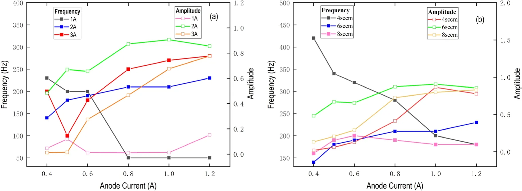
Figure 7.Main peak characteristics of anode current under different working conditions.
4.Conclusion
Discharge instability occurs in the plasma contactor under certain working conditions.The ground experiment is designed to measure the oscillation of the four parameters of keeper voltage,keeper current,anode voltage,and anode current using a voltage and current probe.To ensure the accuracy of the data and the repeatability of the experiment,a simulated anode measuring 800×800×1400 mm3made of stainless steel was used instead of the vacuum chamber used in the conventional ground test.
The experimental results show that when the anode current is between 0.4 A and 1.2 A,the keeper voltage,keeper current,anode voltage,and anode current will oscillate.The increase of the xenon flow and the keeper current will reduce the maximum anode voltage,which is beneficial to industrial applications.When the contactor discharge is unstable,the keeper voltage waveform is generally a sawtooth wave,and the anode voltage waveform is a triangular wave.The keeper current and the anode current can be regarded as being composed of a large-amplitude,low-frequency triangular wave and a smallamplitude,high-frequency sawtooth wave.The frequency of the four parameters is the same when the oscillation occurs,in which the phase of the anode voltage and the anode current is almost the same,the phases of the keeper current and the keeper voltage are almost the same,and the phase of the anode voltage and the anode current is opposite to the phase of the keeper voltage and the keeper current.
Compared with the other three parametric oscillations,the anode current is the greatest and the waveform thereof the most unique.Therefore,the anode current characteristics were mainly analysed and the results reveal that the positive amplitude of the anode current oscillation is much greater than the negative amplitude (this may be due to the emission characteristics of the contactor).The anode voltage in the oscillation interval may correspond to multiple working conditions,and the oscillation will occur between these operating conditions.When oscillating in the direction of increasing anode current,the range of working conditions is greater,so the positive amplitude of the waveform is greater.Meanwhile,we also measured the amplitude and frequency of the main peak where the anode current oscillates under different xenon flow rates and keeper currents.The frequency of the main peak is found to have a low oscillation frequency.However,the amplitude of the main oscillation peak is more complicated and there is no trend therein.
Acknowledgments
The authors would like to acknowledge financial support from National Natural Science Foundation of China (Nos.11402025,11475019,and 11702123);National Key Laboratory of Science and Technology on Vacuum Technology and Physics (No.ZWK1608);and Advanced Space Propulsion Laboratory of BICE and Beijing Engineering Research Center of Efficient and Green Aerospace Propulsion Technology (No.LabASP-2018-03).
ORCID iDs
杂志排行

Plasma Science and Technology的其它文章
- Impact of exterior electron emission on the self-sustaining margin of hollow cathode discharge
- Research on the neutralization control of the RF ion micropropulsion system for the‘Taiji-1’ satellite mission
- On the heating mechanism of electron cyclotron resonance thruster immerged in a non-uniform magnetic field
- Study on the influence of the discharge voltage on the ignition process of Hall thrusters
- The plume diagnostics of 30 cm ion thruster with an advanced plasma diagnostics system
- Performance of a 4 cm iodine-fueled radio frequency ion thruster