Research on the neutralization control of the RF ion micropropulsion system for the‘Taiji-1’ satellite mission
2020-09-14JianwuHE贺建武PengLIU柳鹏RunlianGAO高润莲ChangbinXUE薛长斌LongfeiMA马隆飞LiDUAN段俐andQiKANG康琦
Jianwu HE (贺建武),Peng LIU (柳鹏),Runlian GAO (高润莲),Changbin XUE (薛长斌),Longfei MA (马隆飞),4,Li DUAN (段俐),4 and Qi KANG (康琦),4
1 National Micro Gravity Laboratory,Institute of Mechanics,Chinese Academy of Sciences,Beijing 100190,People’s Republic of China
2 Department of Physics &Tsinghua-Foxconn Nanotechnology Research Center,Tsinghua University,Beijing 100084,People’s Republic of China
3 National Space Science Center,Chinese Academy of Sciences,Beijing 100190,People’s Republic of China
4 School of Engineering Sciences,University of Chinese Academy of Sciences,Beijing 100049,People’s Republic of China
Abstract
Keywords:CNT cathode,neutralization,micropropulsion,Taiji-1
1.Introduction
The Taiji Program in Space for studying gravitational wave physics and the nature of gravity used free falling spacecraft to provide a gravitationally quiet environment[1].The bodies of spacecraft in a microgravity environment appear weightless.However,non-gravitational disturbances,including residual atmospheric drag and solar radiation pressure,can influence precision measurements;therefore,a disturbance compensation system is also used.These systems are frequently described as drag-free control and use microthrusters to provide micro-to millinewtons of thrust to counteract disturbances [2].
The ‘Taiji-1’ satellite mission is the first step of the Taiji Program in Space,which aims to test the key technologies such as high-precision and ultra-stable laser interferometer,gravitational reference sensor,ultra-high precision drag-free control,and ultra-stable and ultra-static satellite platform [3-5].As the main propulsion device of the ‘Taiji-1’ satellite,the radio-frequency(RF) ion micropropulsion system (μRIPS) is mainly used to compensate the non-gravitational forces on the satellite.μRIPS is also one of the key technologies that ensures the success of space experiments of the ‘Taiji-1’ satellite.
The RF ion microthruster (μRIT) allows to accurately control satellites by providing a truly proportional thrust capability in addition to the extremely low thrust noise and sub-micronewton thrust resolution.In combination with ultraprecise gravitational reference sensor,μRIT thrusters allow to accurately control satellite in microgravity,which will allow scientists to detect gravitational waves.
The key component of the μRIT thruster is inductively coupled RF plasma,which provides an ion beam that generates thrust.The μRIT thruster is similar to many other electric thrusters that require a neutralizer to provide electrons for ion beam neutralization.The positive ion beam emitted by the thruster must be accompanied by an electron beam to prevent spacecraft charging [6].Otherwise,the ion loss would quickly cause the spacecraft to become charged to kilovolt potentials,which eventually reduces thrust efficiency to zero and may result in damage to spacecraft systems by the returning ion flux[7].Thus,a neutralizer is required to maintain spacecraft charge neutrality.
In the following sections of this article,the neutralizer performance requirements,type selection,and neutralization control strategy are discussed.The carbon nanotube (CNT)cathode performance,neutralization control effect and environment compatibility are discussed,and some ground test results are presented.The recently acquired results from flight verification experiments are also presented.
2.Neutralization control strategy
The RF ion micropropulsion system on the ‘Taiji-1’ satellite includes two sets of microthruster clusters.Each set of microthruster clusters includes two μRIT thrusters and a neutralizer.This means that one neutralizer needs to achieve the neutralization control of two microthrusters.The desired operating characteristics of μRIT thrusters are the thrust levels of 5-50 micronewtons,exhaust ion levels of 0.05-1 mA,and lifetimes of up to half a year.Thus,the anticipated requirements for a cathode are the reliable emission of electrons of up to 2 mA over half a year cooperation with a xenon ion thruster and a power lower than 5 W.

Figure 1.Schematic diagram of the CNT neutralizer.
To achieve the neutralization control requirements of μRIT in the ‘Taiji-1’ satellite mission,cold field emission cathodes have demonstrated a much higher efficiency,lower system complexity,lighter weight,and smaller dimensions than filament,plasma,and hollow cathodes.The latter cathodes often require heaters,keepers,and propellant feed systems;therefore,it is difficult to miniaturize and reduce their weight.Filament cathodes consume 0.1-100 W mA−1in heater power,and lifetimes are severely limited by thermal cycling [8].Plasma cathodes are insert-free devices that can be employed as electron sources in electric propulsion applications [9,10].Plasma cathodes also reduce the specific impulse of the propulsion system due to use of propellant to sustain plasma.Hollow cathodes have demonstrated a discharge current in the range of 0.3-1 A;these cathodes operate in steady-state conditions at mass flow rates between 0.08 and 0.5 mg s−1of xenon [11].These cathodes require additional power to heat the thermionic emitter.The efficiency of these cathodes increases with an increase in the current as cathode self-heating becomes more effective.Therefore,these cathodes are suitable for high current neutralization tasks.However,the CNT field emission cathodes typically produce between 2 μA and 2 mA of current at voltages between 100 and 600 V;at 1 mA,these cathodes can operate for ∼6000 h[12].CNT cathodes have been developed by BUSEK company for the Lisa Pathfinder Mission (ST7-DRS),and they were qualified in ST7-DRS [13].The schematic diagram of the CNT neutralizer is shown in figure 1.Its structure is very simple,mainly including gate,CNT cathode and some insulating layers.Only a negative high voltage (NHV) power is applied to the cathode to realize electron emission.Thus,we can see that the low size,mass,power,propellantless,and high TRL CNT field emission cathode is very suitable for space and scientific applications such as the ‘Taiji-1’ satellite mission.It also meets the needs of neutralization control of μRIPS.
The control method of ion beam neutralization in an electric propulsion system is typically passive.The principle of this method is simple,and no complex control strategy is needed.The passive control of the electron beam current emitted by the cathode can be realized by the small change of the floating potential to achieve the complete neutralization of the ion beam current and to prevent the spacecraft charging[14,15].However,the passive neutralization control method is typically only suitable for the cathode with low electron extraction voltage such as a hollow cathode.If the electron emission voltage of the cathode is high,such as in CNTN,high floating potential will be produced,which will threaten the safety of spacecraft.In addition,for the electric propulsion system,which requires high precision and low noise thrust,the noise of its floating potential will affect the thrust noise,and the passive neutralization control method cannot meet its requirements.Therefore,we propose an active neutralization control method that is based on PI control strategy to reduce the influence of the floating potential on the thrust noise.
The electric neutral control schematic diagram of the RF ion micropropulsion system is shown in figure 2.Here IA12is the sum of the ion beam current of thrusters TA1and TA2;IB12is the sum of the ion beam current of thrusters TB1and TB2;IAEand IBEare the effective electron beam currents of neutralizers CNTN-A and CNTN-B,respectively;NHV is the NHV power supply for the neutralizer,namely gate voltage;VFPis the floating potential at both ends of the high resistance isolation network (HRIN),namely the high voltage ground end of the electric propulsion system and the ground end of the spacecraft;P1,P2,and P3are the proportional control parameters of the three control loops.The control system consists of two types of control loops.The current control loop(including parameters P1and P2)is designed to make the electron beam almost equal to the ion beam,and the potential control loop(including parameter P3)is designed to make the floating potential almost zero.However,there are capacitive components in HRIN;P3parameters actually play an integral role in the control;thus,the control system is actually a PI controller.

Figure 2.Neutralization control method for μRITPS.
3.Results and discussions
3.1.CNTN acceptance test
CNT field cathodes are now being evaluated for a wide range of applications.However,problems(e.g.short lifetime at high current density,instability under high voltage,and poor emission uniformity) are still major obstacles for their applications[16-18].Then,to meet the needs of the neutralization control of μRITPS for the ‘Taiji-1’satellite mission,Institute of Mechanics,Chinese Academy of Sciences and Tsinghua University worked together to develop a CNT neutralizer that meets the neutralization control requirements of μRITPS.Tsinghua University is responsible for the development of the CNT neutralizer.The auxiliary equipment and environmental compatibility tests of the neutralizer are carried out by the Institute of Mechanics.

Figure 3.Current-voltage behavior of CNTN-A and CNTN-B.
After one year of collaboration,the CNT cathode development team at Tsinghua University successfully solved the problems including short lifetime at high current density and instability under high voltage.The CNT neutralizer is produced using a process in which CNTs are arranged as super aligned fibers.Super-aligned CNT is a type of CNT developed by Tsinghua University.The CNT shows very strong Van der Waals force due to the ultra-clean state.Therefore,the CNT array can be drawn into the film or fiber as the silk from cocoon [19].This arrangement considerably increases the cathode redundancy and robustness.This occurs because only a small part of CNTs is emitting at any time.Regardless of what causes the emission loss of nanotubes,only a small increase in voltage is required to activate more nanotubes to maintain the needed emission current.In addition,the electron emission current can be also controlled by changing voltage between the cathode and the gate.The smaller cathode-gate spacing (the distance between CNT cathode and gate)lowers operating voltages and improves the operating characteristics of the neutralizer but also increases the risk of permanent discharge damage of the cathode.
Two sets of flight parts of CNTN were delivered on time to meet the design requirements.The design index of a single neutralizer is that the electron beam current is not less than 2 mA,the gate voltage is not more than 1200 V,and the electron emission efficiency is higher than 65% (the ratio between the emission electron beam current Ibeamand the cathode current Icathode).Figure 3 shows the actual acceptance test results of flight parts.The Ibeamof both neutralizers is better than 2 mA,the gate voltage is lower than 400 V,and the electron emission efficiency is approximately 75%,which is better than the design index.In addition,the performance of the neutralizer was tested in the ultra-high vacuum of 10−6Pa,and the aging test was carried out for dozens of hours.The aging test is mainly a process of strengthening the experiment on the condition that various factors involved in the actual use conditions have aging on the CNTN.It is also used to eliminate the emission instability during the early stage of neutralizer,so that it could stably work after delivery.
3.2.Environment compatibility tests
To qualify the CNT neutralizers for the ‘Taiji-1’ satellite mission,a number of environmental compatibility experiments were carried out,which primarily included vibration tests,thermal vacuum tests,and propellant exposure tests.The results and discussion of these tests will be presented below.
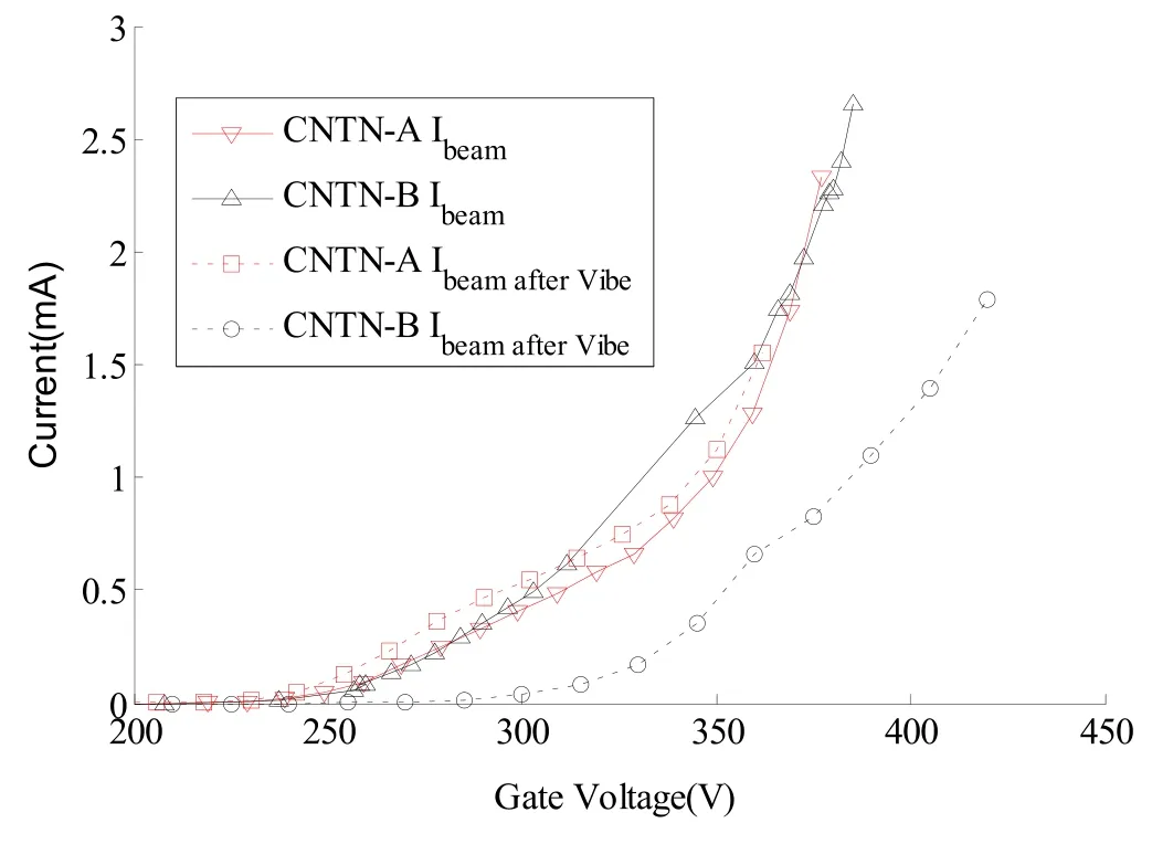
Figure 4.Current-voltage behavior of CNTN-A and CNTN-B after the vibration test.

Figure 5.Performance comparison during the thermal vacuum experiments of CNTN-A and CNTN-B.
The impact,sinusoidal vibration,and random vibration tests were carried out for the CNT neutralizers.The vibration tests were all performed along 3 axes,and the vibration test conditions meet the requirements of satellite engineering.The results of the current-voltage behavior of the CNT neutralizers before and after vibration tests are shown in figure 4.Vibration had no discernable effect on CNTN-A;however,there was some effect on CNTN-B.The operating voltage of CNTN-B was increased by approximately 50 V.This was potentially caused by small changes in the neutralizer structure;however,this change did not affect its normal use.Therefore,the effect of vibration tests on CNT cathodes is very small or negligible.
Two types of thermal vacuum tests were carried out for CNT neutralizer flight parts and RF ion thrusters at the same time.The first test is the acceptance thermal vacuum test,which lasts for five days.The second test is the whole satellite thermal vacuum test,which lasts for one day.The environment temperature of the neutralizer is between−20°C and 45°C,and the vacuum level is better than 5×10⁻⁴Pa.After six days of thermal vacuum tests,the performance degradation of the neutralizers is clear,as shown in figure 5.The operating voltage of the CNTN-A neutralizer increased by approximately 60 V,and that of the CNTN-B neutralizer increased by approximately 145 V.The operating voltage increased too fast in the thermal vacuum tests compared to that in our laboratory.Poor vacuum will accelerate the oxidation of CNT tips during the electron emission state,and the bombardment of a large number of ions will also affect the emission performance of CNTs.In addition,because of the performance degradation of CNTs with large emission current,more CNTs are activated into the emission state so that the emission uniformity is better than before.Thus,the performance of the neutralizer becomes more stable through the thermal vacuum tests.
To study the influence of the xenon propellant on the electron emission properties of the CNT cathode,the xenon propellant exposure test was carried out.It is determined that when the vacuum system is filled with a different mass flow rate of xenon,the CNT cathode current decreased with an increase in the background pressure at a fixed operating voltage.However,when the xenon supply valve was closed and the background pressure was restored,the CNT cathode current returned to the original state.Therefore,the performance of the CNT cathode will decrease when it is exposed to xenon propellant for a short-term;however,this will not cause a considerable long-term damage to the cathode.
In addition,the test results of the CNT cathode exposure to oxygen and ultraviolet light are also introduced in [12].During the ultraviolet exposure tests,it appears that the exposure to ultraviolet light from the Sun will produce very small photoemission currents,and the ultraviolet light had no effect on the CNT cathode emission.During the oxygen exposure tests,the emission current of the CNT cathode gradually decreased with an increase in the background pressure by bleeding in oxygen.Nevertheless,the removal of oxygen returned the cathode current to its initial state.These results confirm that the CNT neutralizer provides a robust electron source for the neutralization control of μRIPS.
Finally,the thruster challenges the performance of the CNT cathode because the produced plasma environment may considerably limit the cathode lifetime if CNTN does not have a compatible structure and materials.When the CNT neutralizer works independently in the ultra-high vacuum environment,its performance declines very slowly,and its lifetime can reach several thousands of hours.When the neutralizer and thruster work together,the performance degradation rate is clearly accelerated.One possible cause is the damage of the CNT tip by the low vacuum level during thruster operation.The other cause is that some low-speed ions in the thruster ion plume return to the neutralizer and sputter CNTs,which reduces the emission performance.To avoid CNT damage caused by ion bombardment,a double grid system can be designed in the future.This type of grid system can extract the electrons from CNTs tip and rebound the external ions.The ions whose energy is lower than the decelerating potential will be repelled.This structure is essential for protecting the CNT emitter tips and can considerably extend the service lifetime of the CNT neutralizer.

Figure 6.Neutralization control effect of CNTN-A.

Figure 7.Performance comparison between the ground and space tests of CNTN-A and CNTN-B.
3.3.Neutralization control effect
To achieve the desired neutralization effect,the active neutralization control method that is based on the PI control strategy needs to debug reasonable PI parameters through numerical simulation analysis.Using the LabVIEW virtual instrument platform,the numerical simulation system of neutralization control was created.According to the current and voltage behavior of the CNT neutralizer,the PI parameters that meet expectations were debugged and then written into the power processing unit for verification.
The neutralization control effect of the neutralizer CNTA working together with the thruster cluster is shown in figure 6.Here,Ielectronrepresents the effective electron emission of the CNTN-A,and Iionrepresents the sum of ion beam ejected by μRIT-A1and μRIT-A2.It is observed that the electron beam current completely changes with an increase in the ion beam current.In addition,the floating potential VFPis stable during the entire process of thrust regulation,and the potential change is not greater than 0.5 V except for the moment of ignition of the thrusters.The results fully meet design requirements and show that this active neutralization control method is very effective.
3.4.Flight verification
The‘Taiji-1’satellite,which was sent into orbit on 31 August,2019,is China’s first drag-free satellite;the satellite completed its first stage tests in orbit and laid a foundation for China’s future gravitational wave observation in space.In addition,μRITPS completed the function test tasks.The system function is normal,and all components are in good condition.The performance of the two CNT neutralizers is shown in figure 7.Flight performance is better than the results of the ground tests owing to the higher vacuum background in space.The obtained results showed that the performance of the neutralizers did not degrade owing to the storage environment,transportation conditions,and vibrations during launch.In addition,when the neutralizer works with the thruster,its performance has almost no attenuation.
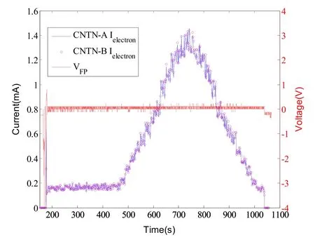
Figure 8.Neutralization control effect of all μRIT thrusters working together.
When all four thrusters are operational,two neutralizers also start to work at the same time.When the four thrusters are adjusted from 5 to 50 μN steps,the electron beam current emitted by the neutralizers changes with the ion beam current almost at the same time,as shown in figure 8.In addition,the neutralization control achieved the expected purpose,and the jitter of the floating potential during the process of thrust regulation was lower than 0.5 V.
Currently,CNT neutralizers have been on and off nearly 100 times in orbit,and after more than four months of space environment tests,their performance is not attenuated,and the emission performance of CNTN-B is even improved.This is a satisfactory result.Next,the lifetime test and the evaluation of the CNT neutralizer will be further carried out in the space ultra-high vacuum environment.At the same time,the lifetime test and evaluation experiments of the neutralizer will also be carried out on the ground.
4.Conclusions
A set of CNT neutralizers for the neutralization control of ion microthrusters was developed using advanced carbon nanomaterials.In addition,the active neutralization control method of multithrusters that is based on the PI control strategy is proposed.The‘Taiji-1’satellite mission successfully realized the μRITs active neutralization control technology.In addition,for first time in China,the neutralization control technology of an ion engine that is based on a CNT neutralizer was verified in space.Although the performance of the neutralizers was attenuated during the ground environmental compatibility tests,their performance almost did not degrade during the flight tests.The obtained results demonstrate that this neutralizer type has good compatibility with a RF ion microthruster.It is clear that this type of CNT neutralizer can be used in other space science missions in the future.
Acknowledgments
This work is supported by the Strategic Priority Research Program of the Chinese Academy of Sciences (Nos.XDB23030300,XDA1502070901,XDA1502070503).
杂志排行
Plasma Science and Technology的其它文章
- Impact of exterior electron emission on the self-sustaining margin of hollow cathode discharge
- On the heating mechanism of electron cyclotron resonance thruster immerged in a non-uniform magnetic field
- Study on the influence of the discharge voltage on the ignition process of Hall thrusters
- The plume diagnostics of 30 cm ion thruster with an advanced plasma diagnostics system
- Performance of a 4 cm iodine-fueled radio frequency ion thruster
- Experimental investigation on the plasma morphology of ablative pulsed plasma thruster with tongue-shaped and flared electrodes