Feedrate scheduling method for constant peak cutting force in five-axis flank milling process
2020-08-11LipingWANGXingYUANHoSIFeiyuDUAN
Liping WANG, Xing YUAN, Ho SI, Feiyu DUAN
a School of Mechanical and Electrical Engineering,University of Electronic Science and Technology of China,Chengdu 611731,China
b Department of Mechanical Engineering, Tsinghua University, Beijing 100084, China
KEYWORDS Cutter runout;Feedrate scheduling;Force control;Instantaneous undeformed chip thickness;Peak cutting force
Abstract It is extremely important to select appropriate feedrates for the stable machining of parts with ruled surface in modern aviation industrial applications.However,the current studies take too much time to achieve this goal. Therefore, this paper presents an efficient feedrate optimization method for constant peak cutting force in five-axis flank milling process. The solution method of the instantaneous undeformed chip thickness (IUCT) is proposed using least squares theory with the cutter entry angle and feedrate as variables.Based on this method,an explicit analytical expression of the peak cutting force for each cutting point is established.Furthermore,a feedrate scheduling method is developed to quickly solve the appropriate feedrate under constant peak cutting force.To verify the proposed IUCT model, the fitting IUCT is compared with the accuracy data at different feedrates.Additionally,some experiments of five-axis flank milling are conducted to demonstrate the effectiveness of the peak force model and the feedrate scheduling method.And the surface roughness before and after feedrate scheduling is detected.The results show that the proposed feedrate scheduling method can quickly adjust the feedrate and ensure constant peak force during machining. At the same time, the surface quality is kept at a high level.
1. Introduction
Five-axis flank milling is suitable for complex ruled surface machining and is widely used in modern aviation industrial applications. With the development of the modern manufacturing industry, a stable machining process of complex ruled surface has become an urgent need in actual production. The cutting force of some cutting points may sharply increase with the conventional machining parameters, leading to vibration and tool breakage.1,2Therefore, in order to make the machining process stable and protect the cutter,the peak cutting force is kept constant in this paper by using the feedrate scheduling method.
Conventional feedrate scheduling methods include online feedrate scheduling and offline feedrate scheduling. Many scholars have carried out related studies on online feedrate scheduling. Adams et al.3presented a new method to identify the controlled system by using closed-loop control strategies in the cutting force control process.Stemmler et al.4proposed a feedrate scheduling method under the given maximum force,which can adjust the feedrate by real-time monitoring of the cutting force. However, these feedrate scheduling methods require the installation of extra sensors, which leads to high cost. In addition, the online feedrate control method is immature. Thus, the offline feedrate scheduling method is still the mainstream.
Offline feedrate scheduling method can be classified into two categories: material removal rate (MRR)-based method and cutting-force-based method.Wang5developed an efficient algorithm based on solid modeling to adjust the feedrate by using MRR-based method. Jang et al.6proposed a voxelbased simulator for multi-axis CNC machining, which can adjust the feedrate adaptively to increase machining productivity according to the MRR.At the same time,the cutting-forcebased feedrate scheduling strategies are also focused by many scholars. Based on the precious researches, Erdim et al.7compared the MRR-based and cutting-force-based feedrate scheduling strategies for three-axis ball-end milling of freeform surfaces. They concluded that the cutting-force-based method is more applicable and reliable than the MRR-based method. The feedrate and other process parameters are adjusted in the cutting-force-based feedrate scheduling process so that the peak cutting forces are constant at each cutting point. This step reduces vibration in the machining process and protects the cutter. According to the conclusion proposed by Erdim, Salami et al.8studied the feedrate scheduling method for three-axis ball-end milling to improve the production efficiency. But the situation in five-axis is different from that in three-axis. Thus, Layegh et al.9kept the cutting force constant along the tool path by adjusting the feedrate, significantly improving the five-axis machining efficiency of the complex ruled surface.However,this feedrate scheduling method is time-consuming.Based on this method,Park et al.10developed an automated machining system and scheduling strategy to predict and improve the performance of milling operations.However, the experimental results showed that the peak cutting force is different at each cutting point, which cannot satisfy the target precision in feedrate scheduling progress.
The above cutting-force-based feedrate scheduling process usually requires complex iterative calculation to reach the target feedrate. The design of iterative calculation becomes complicated when the feedrate is scheduled under multi-objective constraints. Thus, the proportional (P) adjustment method is widely used in the feedrate scheduling process. Meanwhile,the proportional plus integral (PI) adjustment method and the proportional and derivative (PD) adjustment method also show good applied prospect. Sun et al.11presented a feedrate scheduling method for the five-axis machining of complex part with geometry, process and drive constraints, which applies P adjustment method to adjust feedrate. But Sun did not consider the influence of contour error.Based on this,Dong et al.12presented a real-time smooth feedrate planning algorithm for short line tool path, in which the contour error constraint is included and the PI adjustment method is applied in the algorithm. Subsequently, Chen et al.13proposed an adaptive feedrate planning strategy with PD adjustment method to improve contouring accuracy. An offline feedrate planning method constrained by the contour error, axis acceleration,jerk, and chord error is developed by Chen et al.14In this method,the feedrate is scheduled with P adjustment.All these methods are intuitive during the feedrate adjustment process and are suitable for multi-constraint feedrate adjustment process. However, whether the conventional iterative method or the P adjustment method, it is inevitable to constantly change the feedrate to reach the target value.And this calculation process will be more complicated with the high target precision.Therefore,it is necessary to propose a new feedrate scheduling method to avoid iterative calculation and quickly obtain the scheduled feedrate.
The establishment of a cutting force simulation model is the premise of feedrate scheduling.15And IUCT is a critical problem in a cutting force simulation model. Martellotti16,17first proposed an approximate arc model h=fsinφ for IUCT in milling with a straight line tool path. This model is a classic arc model and many scholars study IUCT based on this model.However, cutter runout and various tool paths increase the complexity of the studies.18,19Wang and Liang20considered the effect of tool offset on IUCT and developed additional corrections. Wan et al.21proposed an IUCT model that accounts for cutter offset and cutter inclination. But they did not consider the interaction of tooth trajectories. For solving this issue,Desai and Rao22,23analysed the interaction of tooth trajectories and considered the effect of cutter offset on entry/exit angles. However, the above models are the modified form of the arc model.During the five-axis machining process of complex ruled surface,the cutter/workpiece engagement region is a complex and irregular polyhedron. Ferry and Altintas24presented a mathematical model for predicting the cutting force of five-axis machining with tapered,helical,ball-end mills with variable pitch and serrated flutes.However,the effect of cutter runout is not considered in this study. Thus, Sun and Guo25presented a new method to effectively model and predict the instantaneous cutting force in five-axis milling process with radial cutter runout based on tool motion analysis. Meanwhile, Sun and Guo26established the envelope surface model considering cutter runout effect in five-axis flank milling based on the relative motion analysis of the cutter and part, which provides a theoretical base for cutting force prediction in five-axis flank milling.Based the study of Sun,Wu et al.27presented a cutting force prediction model for the circular end milling process, but this method is complicated and timeconsuming. At the same time, Cao et al.28presented an improved mechanistic cutting force model for multi-axis ballend milling and take cutter runout into account. However,Li and Zhu29found that the actual rotating radius of each flute differs from its nominal value owing to the existence of the cutter runout. To distinguish the cutter runout error,Zhu et al.30proposed a cutting-edge element moving method to simulate a five-axis machining cutting force considering runout for general end mills. Actually, for five-axis flank milling, the real tooth trajectory is a three-dimensional trochoid motion.Based on the actual tooth motions in five-axis flank milling, Zhang et al.31studied the influence of complex tool paths, workpiece geometries and cutter runout on the IUCT and entry/exit angles. But the method developed by Zhang is complex and the iterative calculation process is unavoidable, which makes the calculation progress time-consuming. Based on the study of Zhang, Guo et al.32proposed a cutting force model for five-axis machining based on the parameterized error compensation chip thickness. This model is not only suitable for general flat end mills but also flat end mills with variable helix and pitch angles. Although the iterative calculation process is avoided in this method, it did not take into account the cutter runout, and the calculation method is still cumbersome. The cutting force model need to be calculated many times in the feedrate scheduling process.The complex cutting force calculation method severely limits the feedrate scheduling efficiency,and the low-precision cutting force model severely affects the reliability of feedrate scheduling. Therefore, it is extremely important to propose a high-precision and efficient cutting force calculation model.
To avoid the iterative calculation process of the conventional feedrate scheduling process, this paper proposes a cutting force model with the entry angle and feedrate as variables,which considers the effects of variable surface curvature of workpiece and cutter runout.Then,the functional relation of feedrate and peak cutting force at each cutting point is established. Finally, the feedrate is optimized based on the constant peak cutting force. Several five-axis flank milling studies are carried out. The simulation and experiment comparison verifies the effectiveness of the cutting force model and the feedrate scheduling method. Through the simulation time comparison,it is verified that the feedrate scheduling time is greatly improved compared with the existing method. And this method provides a theoretical basis for software to realize fast feedrate scheduling based on constant cutting force. The main contributions of this paper are as follows: 1. A highprecision and high-efficiency peak force model is developed with the entry angle and feedrate as variables.2.Based on this model, a high-efficiency feedrate scheduling method is proposed for the five-axis flank milling process.
The organization of this paper is presented in the following order. The cutting force model in the five-axis milling process is discussed in Section 2.Section 3 establishes a high-precision and high-efficiency cutting force model for five-axis flank milling.A feedrate scheduling method based on constant force is discussed in Section 4. The experimental validation is described in Section 5. Conclusions are drawn in Section 6.
2. Cutting force model in five-axis flank milling


Fig. 1 General five-axis flank milling process.
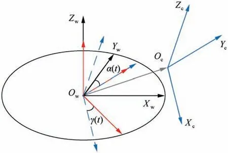
Fig. 2 Establishment of a cutter system.
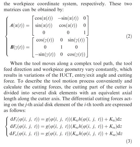
where dFt(φ(i, j, t)), dFr(φ(i, j, t)) and dFa(φ(i, j, t)) are the tangential, radial and axial cutting forces for the cutter on the j-th axial disk element of the i-th tooth at time t,respectively; dz is the thickness of each axial disk element; Ktc, Krcand Kacare the shearing specific cutting force coefficients in the tangential, radial and axial directions, respectively; Kte,Kreand Kaeare the ploughing specific cutting force coefficients in the tangential, radial and axial directions, respectively; the parameter φ(i, j, t) is the location angle for the cutter;h(φ(i, j, t)) is the IUCT at the location angle; g(φ(i, j, t)) is a window function which determines whether the current disk element is involved and can be assigned a value by:

where φst,i,jand φex,i,jare the entry and exit angle on the j-th axial disk element of the i-th tooth, respectively. The total forces acting on the cutter system at time t can be obtained by summing the local cutting forces acting on each disk element, which can be expressed as:
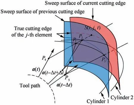
Fig.3 A calculation method of the IUCT in the five-axis milling process.


3. Expression of peak cutting force at each cutting point
3.1. Definition and analysis of IUCT
An IUCT calculation method based on the trochoid curve trajectory is shown in Fig.3.Point S(i, j, t)is the current cutting edge point on the j-th axial disk element of the i-th tooth at time t. Time Δt is the unit teeth cutting time. Points P4and P5are the cutter centres on the j-th element at time t and t-Δt,respectively.Vectors a(t)and a(t-Δt)are the axis vectors of the cutter at time t and t-Δt, respectively. The tool cylinder at time t-Δt is named‘Cylinder 1’.‘Cylinder 1’intersects cutting edge of the (i-1)-th tooth on the j-th element at point P3and intersects line segment P4S(i, j, t)at point P1.In the region of cylinder 1, the approximate time consumed between point P1and point P3is denoted as Δt1. The tool cylinder at time t-Δt+Δt1is named ‘Cylinder 2’. ‘Cylinder 2’ intersects line segment P4S(i, j, t) at point P2. In this case,the actual IUCT can be expressed as:

where h(i, j, t) is the value of IUCT; lP2S(i,j,t)is the length of line segment P2S(i, j, t).
In this method, the value of IUCT is analysed at a special moment.Different from the arc model mentioned in Section 1,the IUCT value is regarded as the length of line segment P2S(i, j, t) rather than the length of P1S(i, j, t). Therefore,the calculation process of point P2is the most critical problem.The calculation process of point P2in the conventional IUCT calculation method is time-consuming. The specific IUCT calculation method as shown in Fig. 3 has been carefully introduced in Ref. 32 However, they ignore the effect of cutter runout. In fact, the cutter runout is unavoidable during machining. According to the research of Ref. 23, the cutter runout of flank milling includes axial and radial components.Generally, axial cutter runout is extremely low and can be minimized through the application of reference surface installation.Therefore,only the radial cutter runout is considered in this paper. The radial runout on the cutter geometry is shown in Fig.4.A mathematical formula was developed in Ref.33 for describing the variation of cutting point radius results from radial cutter runout as follows:

Fig. 4 Cutter radial runout.

where R(i, j)is the actual cutting point radius on the j-th axial disk element of the i-th tooth; R0is the original radius of the cutter; ρ is the radial offset value; λ is the orientation angle for radial offset; β is the tool helix angle. For the description,tooth 1 with long actual cutting radius is named high tooth,while the other teeth with short actual cutting radius are named low tooth, as shown in Fig. 4.
According to the research of Ref.23,cutter runout leads to the variation of radii between cutting teeth on the same axial disk element, and further results in different values of IUCT.To make the calculation of IUCT more practical, the interaction of the cutting tooth trajectory in the process of computer simulation should be considered. The actual IUCT of the tooth at time t is defined as the minimum of all adjacent IUCTs calculated from Eq. (7), which can be expressed as:
h(i, j, t)=max[0, min(hm(i, j, t))] (9)
where m=1, 2, ... , N; hm(i, j, t) is the distance between the j-th axial disk element of the i-th tooth trajectory and the(i-m)-th tooth trajectories at time t.
When the effect of radial cutter runout is considered, the IUCT defined by Eq. (7) is closer to actual value. However,a complex relationship of feedrate and cutting force is presented with this IUCT calculation method. Using this method for feedrate scheduling, iterative computation is unavoidable.This feedrate scheduling method is a time-consuming process,and even occurs non-convergence in the calculation.Thus,it is necessary to develop an explicit calculation expression of peak cutting force.In this process, simplified expression of IUCT is a critical problem, which is discussed in the next section.
3.2. IUCT fitting process
According to the arc model developed by Martellotti16, the relationship between the feed per tooth and the IUCT can be approximated as:

where fzis feed per tooth. Compared with the arc model, the trochoid model is closer to the actual situation. Thus, the establishment of the IUCT simplified expression should base on the trochoid model.
According to Eq. (10), the arc model of IUCT is a function with feed per tooth fzand location angle φ(i, j, t) as variables. In the arc model, h(i, j, t) can be fitted by φ(i, j, t) when fzis constant. According to Ref. 34, there is a less error between the IUCT value calculated by the arc model and the trochoid model. Therefore, when fzis constant, h(i, j, t) can also be fitted by φ(i, j, t) in trochoid model. Additionally, when φ(i, j, t) is constant, there is a positive correlation relationship between the feed per tooth fzand the calculation error of these two models according to Ref. 35 Thus, a nonlinear relationship including the IUCT, the feed per tooth and the location angle can be obtained by polynomial fitting as follows:
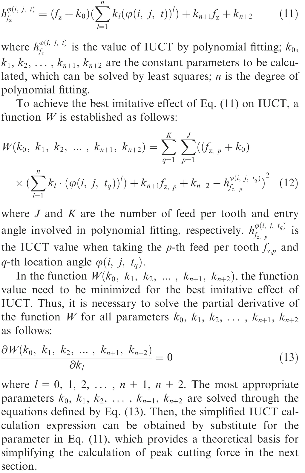
3.3. Peak cutting force analysis
The resultant force is closely related to the surface roughness according to Ref.36 Meanwhile,the resultant force has a close effect on the vibration in Ref. 37 According to Ref. 38, there are many researches of resultant force on the deformation compensation, vibration, and tool wear. In general, the resultant force of the cutter changes constantly along the tool path during five-axis flank milling process. Fig. 5 shows the relationship between resultant force of cutter with two teeth and cutting time in five-axis flank milling process.
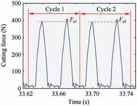
Fig. 5 Resultant force of cutter.
In this figure,‘Period 1’and‘Period 2’are the periodic time of the cutter. The maximum forces Fp1and Fp2are the peak cutting force of‘Period 1’and‘Period 2’,respectively.According to Ref. 39, the peak cutting force can cause some negative effects, such as tool breakage and spindle damage. Excessive peak cutting force affect the quality and dimensional accuracy of machined surface. Thus, in the process of feedrate scheduling based on cutting force, the peak cutting force is selected.The solution of peak cutting force is the premise. In the conventional calculation of peak cutting force, the comparison of cutting forces at all time-points is unavoidable.The conventional calculation method of peak cutting force severely restrict the efficiency of feedrate scheduling. Therefore, a simplified calculation expression of peak cutting force is necessary to be developed.
To develop the simplified expression of peak cutting force, solving the time-point of peak cutting force is also an important issue besides the simplified expression of IUCT in Section 3.2. To find this time-point, all the cutting cases of only a single high tooth involved in cutting with high radial depths of cut employed is considered, as shown in Fig. 6. And Fig. 6(e) shows the resultant force of the cutter in the four cases.
The instantaneous value of the cutting force in the case of Fig. 6(b) is larger than that in other cases through the cutting force simulations.Therefore,the peak force will exist when the first time the high tooth of the cutter is completely embedded in the workpiece during machining. When the low radial depths of cut are employed,the cutting force in case 1 and case 2 are almost equal to peak force, as shown in Fig. 7. In this case, peak force will appear when the first time the axial disk element exit from the workpiece.
Based on the discussion presented above, the computational method for the peak cutting force can be transformed into the calculation of the cutting force at a specific moment when a single tooth is involved in cutting.Then, based on Eqs. (3)-(5) and (11), the projection of the peak force in the x-direction of the cutter system can be expressed by:
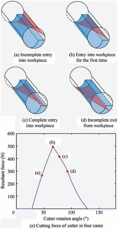
Fig. 6 Four cases of a single tooth involved in milling process.

Fig. 7 A case of a single tooth involved in milling process.

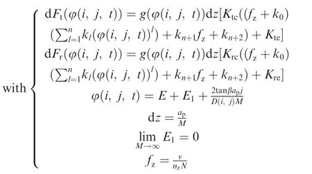
where apis the axial depth of the cutter;E is the entry angle of the cutter,which varies with the workpiece curvature along the tool path; E1is the cutter rotation angle of the first axial disk element when entering the workpiece for the first time, and decreases as the number of axial disk elements increases; v and nzare feedrate and spindle rotation speed, respectively.D(i, j) is the actual cutting diameter on the j-th axial disk element of the i-th tooth. To simplify the calculation, D(i, j) in Eq. (14) can be approximated as D(imax), which represents the actual diameter on the high tooth.
When the number of axial disk elements M is sufficiently large and the high tooth is involved in cutting, the projection of the peak force value in the x-direction can be approximately shown as:

where u is the integration variable, φ(u) is the location angle function with u as its variable.
Then, Fc,x,maxcan be easily solved out using the following integral formulas:

Similarly, Fc,y,maxand Fc,z,maxare the projection of the peak force in the y-and z-directions,respectively.Then,based on Eqs. (3)-(5) and (14)-(16), the components of the cutter in the x-,y-and z-directions can be expressed as the function of the feed per tooth fzand the entry angle E:

where f1, f2and f3are the function relationship, as detailed in the appendix.Thus,the simplified peak force can be calculated as follow:where Fc,maxis the peak cutting force of the cutter.

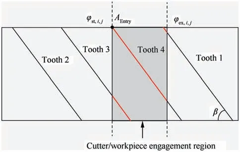
Fig. 8 A case of multi-toothed cutting.
The above method is suitable for single tooth cutting.However, a special case of multi-toothed cutting may occur when high axial depths of cut are employed, as shown in Fig. 8.The peak force exists when point AEntryin Fig.8 is at the same location as point Q in Fig.4.In the case of multi-toothed cutting,all the teeth in Eq.(14)need to be judged for solving cutting force, but does not make Eq. (17) too complicated.Additionally, the methods for calculating cutting force coefficient and entry angle are from Refs. 40 and 41, respectively.After the simplified peak cutting force is put forward, a new method of feedrate scheduling can be developed, which is discussed in the next section.
4. Feedrate scheduling method
In Section 3,simplified peak cutting force is a function of feed per tooth and entry angle, which provided a new method for feedrate scheduling. Based on Eq. (17), Eq. (18) can be transformed into:

where a0,b0and c0are the parameters of entry angle obtained from Eq.(18).However,the solutions of Fc,x,max,Fc,y,maxand Fc,z,maxin Eq. (18) are involved in definite integral. Further,the solving process of definite integral need to be divided into several parts.One of the parts is the integral process of triangle function and polynomial, which is a complex calculation process.Thus,Eq.(16)is employed to solve this problem.Finally,the integral process can be transformed in to an equation for peak cutting force Fc,maxand feedrate fz. Then, the three parameters a0b0and c0can be obtained. The whole solution process involves a lot of derivation process and simplification process, which are specified in the appendix. According to the relationship v=Nfznzand Eq. (19), the solution of feedrate v is:

Therefore, when the target peak force of feedrate scheduling is given, it is easy to solve for the optimized feedrate v.The feedrate in this paper is directly solved out by Eq. (20),which avoids the complicated scheduling process and thus the simulation time of feedrate scheduling is greatly shortened.To clearly explain the advantages of the feedrate scheduling method in this paper,the flow charts of the feedrate scheduling method proposed in Ref. 9 and the method developed in this paper are shown in Figs. 9 and 10, respectively.

Fig. 9 Conventional feedrate scheduling process.

Fig. 10 New feedrate scheduling process in this paper.
There are two time-consuming processes which are inevitable in the method of Fig.9.First,the peak force of each cutting point is obtained by comparing the cutting forces at all timepoints during the period of the cutting point, which becomes more time-consuming as the number of angular integration steps and axial disk elements increases. Second, to achieve the target peak cutting force,the iterative computation process is necessary. Thus, compared with the previous method, the new scheduling process has high precision and can greatly shorten the calculation time. After obtaining the feedrate based on constant force feedrate scheduling, the acceleration and acceleration images are further analysed. Then through the method in Ref. 12, the regions where the feedrate changes rapidly are smoothed.
5. Simulation and experimental results
To verify the accuracy and efficiency of the proposed feedrate scheduling method during the non-developable ruled surface machining, several five-axis flank milling experiments are conducted based on the discussion above.First,the IUCT is fitted,and the imitative effect is evaluated.Then,the accuracy of the peak force is verified by comparing the five-axis flank milling experiments with the computer simulation. Finally, the feedrate is optimized, and the accuracy and efficiency of the method are evaluated.The workpiece to be machined is shown in Fig. 11, and the three-dimensional control points of the ruled surface are shown in Table 1. The S-shape part showed in Fig. 11 is scaled down from the standard S-shape part.The standard S-shape test piece is designed for detecting the five-axis machining performance of machine tools. It has two ruled sidewalls, which are defined by two quasi-uniform cubic rational B-splines. During the machining of the S-shape test piece, the tool axis must be continuously transformed, so the application will illustrate the effectiveness of the proposed method for quickly obtaining the scheduled feedrate in the five-axis flank milling process.

Fig. 11 Machining experiment.

Table 1 Control point parameters of the non-developable ruled surface.
5.1. IUCT fitting model evaluation
The workpiece material is aluminium alloy 7050.The cutter is a two-flute solid-carbide end mill with a diameter of 12 mm and a helix angle of 30 degrees.The cutter radial runout value ρ and the orientation angle λ are identified according to the method introduced in Ref. 42. The results are ρ=0.002 mm and λ=37.45 degrees. The cutter rotation speed is 1000 r/min and original feed rate is set to 200 mm/min.
To obtain the fitted IUCT model, a series of IUCT values that vary with the location angle are calculated by the method presented in Section 3.1. A total of 1500 sets of data with 0.01 rad intervals for the location angle unit and ten different feedrates are selected for fitting the parameters in Eq.(11).The parameter values obtained by fitting process in Section 3.2 are k0=0.0048, k2=-0.4708, k3=0.0259, k4=0.0241,k5=0.99, and k6=0.0009 (taking n as four). To evaluate the fitting precision of IUCT model, the error rate expression is developed as:

where η is the error rate;h1is the value of the IUCT calculated by the fitting expression;h2is the value of the IUCT calculated by the model presented in Section 3.1.
To clearly show the error rate,Fig.12 with three subfigures are drawn. In this figure, the fitting error rates of the IUCT calculated according to Eq. (21) for different feeds per tooth and different location angles.The variable of abscissa E represents the location angle. It is clear that most of the error rates are less than 0.3%.When the location angle is greater than 80 degrees,the error rate is large.In fact,the absolute error is less than 0.001 mm when the location angle is larger than eighty degrees, which has little effect on the final calculation for the peak force.
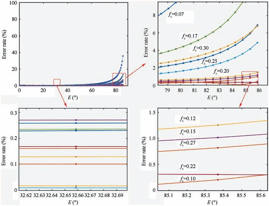
Fig. 12 IUCT fitting error rate.

Table 2 Solution time of the IUCT for different methods.
The computational time for the proposed method also needs to be considered besides the fitting precision. The computer used for simulation is an Ideapad700 with an Intel(R)Core(TM) i7-6700HQ@2.60 GHz CPU and 8.00 GB of RAM. A 64-bit operating system and MATLAB 2017 are chosen to run the program. The time range is t=0.507:0.001:0.6. For the selected workpiece in Section 5, t1,t2and t3are the simulation time of methods proposed in Ref.31, Ref. 32 and this paper, respectively. The results are shown in Table 2.It is clear that the simulation efficiency of this method is greatly improved compared with the previous methods.
Fig.13(a)and(b)show the simulated and measured cutting force values in the x-axis direction at each cutting point.Fig. 13(c) and (d) show the simulated and measured cutting force values in the y-axis direction at each cutting point.
Through comparison and analysis, the following conclusions can be drawn:
(1) It is clear that the predicted and experimental results are in good agreement. This finding shows that the method presented in this paper can predict cutting forces during five-axis flank milling process.
(2) Due to the existence of IUCT fitting error and tool deformation, the cutting force of the experimental results is slightly smaller than the simulation value.
5.2. Five-axis machining cutting force experiment
The machining experiment of the workpiece in Section 5.1 is carried out. Additionally, the cutting force coefficient identification of the end milling cutter is identified by the method introduced in Ref. 40. The calculation results are Ktc=974.13 N/mm2, Krc=219 N/mm2, Kac=87.6 N/mm2,Kte=37.8 N/mm, Kre=53.2 N/mm and Kae=20.17 N/mm. The cutting conditions for the flank milling process are a radial cutting depth of 1 mm, an axial cutting depth of 10 mm,and a feed per tooth of 0.1 mm/z.To ensure machining accuracy, the same cutter is used throughout the process. The real-time cutting force data during the machining process are measured by a Kistler 9257B three-way dynamometer.
5.3. Feedrate scheduling experiment
The workpiece used in this paper includes open angle region,closed angle region and flat angle region. In the open angle region and closed angle region, the peak force varies with the changes of workpiece curvature and tool tilt angle. However, the peak force in the flat angle region is always constant and the value is between closed angle region and open angle region. Therefore, the selection of the peak force (273 N) in the flat angle region can adjust the peak force that is too large or too small. Table 3 shows the feedrate simulation time for different methods described in Section 4 at one cutting point.In the simulation process, T1and T2are the simulation time for the method in this paper and the method in Ref.9,respectively. It is clear that the simulation time is 8.23 times shorter than that of the conventional method when the target accuracy is taken as 1 N.
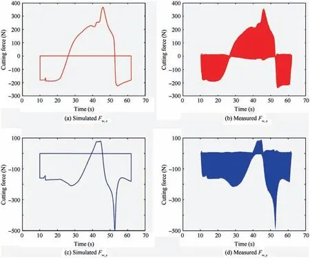
Fig. 13 Comparison between simulated and measured cutting forces for five-axis flank milling process.

Table 3 The solution time of the feedrate at one cutting point.
Then,the tool position file is changed according to the feedrate scheduling method presented in Section 4. The different feedrates before and after scheduling are shown in Fig. 14. It can be seen that the feedrate between 20 s and 40 s is larger obviously,which is caused by the increscent entry angle due to the varying curvature.Therefore,increasing the feedrate to increase the cutting force is necessary.Meanwhile,the feedrate between 50 s and 70 s is smaller obviously.Accordingly, decreasing the feedrate to equalize the cutting force is conducted.
The feedrate shown in Fig.14 reflects large acceleration and deceleration phenomenon locally,which may lead to trajectory error and overcut/under cut. In order to avoid this case, the feedrate is smoothed with the method in Ref. 12. The regions of feedrate curve with large acceleration and deceleration such as ‘Region 1’, ‘Region 2’ and ‘Region 3’ are shown in Fig. 15(a).As shown in Fig.15(b),the three regions of feedrate curve are smoothed, while the other regions are almost the same as before.
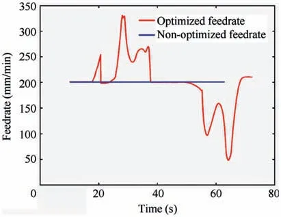
Fig. 14 Comparison of feedrates before and after optimization.
After the feedrate is smoothed, the same workpiece is machined again using the optimized feedrates while other machining parameters remain unchanged. Additionally, the real-time cutting force data are collected during the machining process.Fig.16(a)shows the measured cutting force of the cutter before scheduling, and Fig. 16(b) shows the cutting force after scheduling.From these two figures,the following conclusions can be drawn:
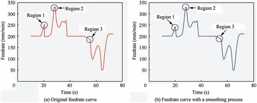
Fig. 15 Comparison of feedrates before and after a smoothing process.

Fig. 16 Changes of resultant force before and after feedrate scheduling.
(1) The effect of the feedrate scheduling method presented in this paper is obvious:the resultant force of the cutter is kept stable after scheduling.
(2) It is clear that the optimized feedrate is closely related to the non-optimized resultant force, which shows that the feedrate should be reduced when the non-optimized resultant force is greater than the optimization target.Otherwise, the feedrate needs to be increased.
(3) To protect the cutter and reduce vibration, the feedrate at a high cutting force needs to be reduced, which extends the machining time in this paper. Additionally,the optimized target resultant force can be increased to improve the machining efficiency.
5.4. Surface quality measurement
After feedrate scheduling based on the constant force, the surface quality before and after the feedrate scheduling is measured. Region A is the region to be measured as shown in Fig. 17(a). And the experiment setup is shown in Fig. 17(a). The measuring results of profile with original feedrate and scheduled feedrate are shown Fig. 18(a) and (b), respectively. Then, the value of surface roughness can be calculated by the equation shown as follows:

where Rais the average deviation in contour arithmetic; lais the measured length; yais the contour height value of measured points in Fig. 18.
According to the Eq. (22), the value of Racalculated by Fig. 18(a) and (b) are 0.4924 and 0.4521, respectively. It can be known that the surface quality machined with the scheduled feedrate is better. Therefore, the feedrate scheduling method based on constant force in this paper can quickly obtain the scheduled feedrate, protect the cutter, make the machining process stable and maintain the high surface quality at the same time.

Fig. 17 Surface quality inspection experiment.

Fig. 18 Comparison of profile.
6. Conclusion
This paper introduces a feedrate scheduling method based on constant cutting force with the entry angle and feedrate as variables. After modelling and verification, the following conclusions can be drawn:
(1) This paper develops an IUCT fitting model with the entry angle and feedrate as variables. The results of the error rate prove that the model provides highprecision IUCT values and greatly improves the calculation speed compared with the previous methods.
(2) A peak force explicit expression based on the IUCT fitting model is presented in this paper.Compared with the previous methods, the complicated process for calculating the maximum cutting force in the conventional method is avoided, and the solution efficiency for the peak force at a single tool point is greatly improved.
(3) The expression of the feedrate is solved by the expression of the peak force. Then, a constant cutting force is selected to solve the feedrate directly, which avoids the complicated iterative computation process.The simulation time of feedrate scheduling is 8.23 times shorter than that of conventional method.
(4) The feedrate scheduling method for constant cutting force developed in this paper makes the machining process stable, which protects the cutter and reduces vibration. At the same time, the surface machined can keep high surface quality. The method in this paper can also be applicable to feedrate scheduling for improving machining efficiency.
Acknowledgement
This study was co-supported by the Major National S&T Program (2017ZX04002001) and the Major National S&T Program (2016ZX04004004).
Appendix A.To calculate the parameters a0, b0, and c0in Eq.(19), detailed calculation process is given now.
According to Eqs. (3)-(5) and (14)-(16), the component of the tool in the x direction can be obtained based on the relationship between the feed per tooth fzand the entry angle E:


杂志排行
CHINESE JOURNAL OF AERONAUTICS的其它文章
- An experimental method for squealer tip flow field considering relative casing motion
- A novel none once per revolution blade tip timing based blade vibration parameters identification method
- Highly efficient computation method for hazard quantification of uncontained rotor failure
- Optimal motion cueing algorithm for accelerating phase of manned spacecraft in human centrifuge
- Effective control allocation using hierarchical multi-objective optimization for multi-phase flight
- Fault-tolerant control and vibration suppression of flexible spacecraft: An interconnected system approach
