Review: Scalable Fabrication of Polymeric Nanofibers from Nano- Spinning Techniques to Emerging Applications
2020-07-16JianLuZexuHuQianqianWangMatteoCiprianXiangFeiandMeifangZhu
Jian Lu, Zexu Hu, Qianqian Wang,Matteo Ciprian, Xiang Fei and Meifang Zhu
(State Key Laboratory for Modification of Chemical Fibers and Polymer Materials, College of Materials Science andEngineering, Donghua University, Shanghai 201620, China)
Abstract: Research in the nanofibers field is attracting an ever-increasing attention from the industrial and academic sector. This attention is justified by the high specific surface area and high porosity, diversity of physical/chemical modification, and simplicity of hybridization. This review summarizes the state-of-the-art progress on the fabrication of polymeric nanofibers (PNFs) with particular emphasis on their scalable productions for emerging applications. First, the engineering processes and equipment for PNFs production are briefly introduced, and the effects of the polymer precursors, operational parameters, and environmental conditions on the nanofiber’s formation are illustrated. The past achievements and current challenges of PNF preparation in industrial production are also discussed. Hybridization methods to prepare multifunctional composite nanofibers are also reviewed, including organic incorporation modification, loading functional inorganic nanomaterials, and biological active components on/into nanofibers. Given these hybridizations and functions, a variety of applications are then discussed, focusing mainly on environmental and biomedical applications. Finally, conclusions are drawn and prospects are given according to the reviewed research.
Keywords: nanofiber, polymer, nano-spinning technique, hybridization, application
1 Introduction
Nanofibers have no clear definition so far. They are generally recognized as one-dimensional materials with the following characteristics: nano-sized diameter (< 1 μm), sufficient length (diameter ratio > 1000), and flexibility. Compared with polymeric fiber materials with diameter of micrometers (e.g. 10-100 μm), materials with diameter of nanometers(e.g. 0.1-10×10-3μm) present outstanding characteristics, such as large specific surface area which results in characteristically different physical and chemical properties; and compared with nano-sized materials with any other form, nanofibers with fiber form are more flexible and conducive to continuous preparation and recovery[1-3]. These properties make the PNFs prime candidates for many important applications. After two decades of research, the excellent performance of PNFs has been well demonstrated in many scientific and industrial fields, such as high-efficiency filtration, biomedicine, nanocatalyst, battery separators, and so on[2]. With the intensive development of hybridization technologies, hybridized PNFs can combine the designability of synthetic polymer matrix with the functional specificity of organic, inorganic materials or biomolecules, thereby enabling the function of PNFs to be more efficient, controllable, and intelligent[4-9].
All along, out-of-the-laboratory and scalable production of PNFs is always a critical research subject. Although there are a large number of methods for preparing nanofibers in the laboratory, for example,self-assembly[10], nanolayer coextrusion[11], phase separation[12], and templated methods[13], they can only prepare nanofibers in batches. Thus, technical and economic factors are still challenges that need to be tackled. Therefore, efficient, stable, and controllable preparation technology is the key component to unlock the commercialization of PNFs. This paper provides a brief review of engineering techniques for PNFs production, followed by a general summary on hybridization strategies and emerging applications.
2 Scalable Fabrication Techniques for PNFs
2.1 Electrospinning
Electrospinning is the simplest and most widely applied technique for preparing nanofibers[1-2]. In the recent decade, electrospun ultrafine fibers have been successfully prepared with various polymers solution or melt. There are three basic components that constitute the equipment: a voltage supply, a syringe with a spinneret, and a collector. In the electrospinning process, a high voltage is used to create an electrically charged jet of polymer solution or melt out of the pipette. The charged polymer solution or melt forms a cone shape (which is known as Taylor cone[14]) because of the force balance. With the electrostatic force increasing, the charged fluid ejects from the tip of such Taylor cone and becomes jet, and the charged jet is stretched and forms fibers with solvent evaporation or melt cooling between the spinneret and the collector. Eventually such fibers are collected with the collector and form a fibrous membrane[15].
It is well demonstrated that electrospun nanofibers’ morphology is relative with the following factors (Fig. 1)[16-19]: 1) the characteristics of the electrospinning setup, such as the feed rate of the electrospun solution, the structure and the diameter of spinneret, the distance between spinneret and collector, the shape, the voltage of power supply, material and moving trail of collectors; 2) the properties of the electrospun solution, including the molecular weight of polymer, solvent boiling point, the concentration of the solution which is related to the viscosity, and the presence of additives which is related to conductivity; 3) environment properties such as humidity and temperature having influence on the evaporation of solvent, which is important to nanofibers’ morphology. With the optimization of the parameters above, continuous nanofibers with uniform morphology can be achieved.
Traditional PNFs prepared by electrospinning use poly vinylpyrrolidone (PVP), poly vinylidene fluoride (PVDF), and poly vinylacetate (PVA)[16, 20-22]as polymer matrix. In recent years, electrospun hybrid PNFs are more and more popular, which include organic hybridization with polymers or organic small molecule, inorganic hybridization with nanoparticles of metals, metal oxides, ceramics, and carbon materials[4, 23-25]. Moreover, the improvement of multi-component electrospinning technology promotes the development of hybrid PNFs, which makes the distribution of different components more controllable and results in more ordered morphology. Among them, core-shell nanofibers prepared by coaxial spinnerets are typical (Fig.2 (a)-(i))[26-29]. In 2002, Li et al.[26]prepared hollow nanofibers using a self-made coaxial spinneret with heavy mineral oil as core solution and PVP-Ti(OiPr)4sol-gel precursor in ethanol as shell solution (Fig. 2(a)). Owing to the poor compatibility between such two solutions, the shell layer of nanofibers and the continuous core layer of heavy mineral simultaneously formed as the solvent of shell solution evaporated. Afterwards, such as-electrospun nanofibers were treated with octane to extract heavy-mineral-oil formed core layer, leading to the hollow structures (Fig. 2(b)-(d))[26].In addition, the arrangement of nanofibers in electrospun membranes can be aligned by adjusting the moving trail of collector and the distribution of electric field[30-32].

Fig. 2 Schematic illustration for preparing electrospun nanofibers with (a)-(d) traditional core-shell structure (Reprinted with permission from Ref. [26]. Copyright 2004, American Chemical Society); (e)-(f) multi-channel structure (Reprinted with permission from Ref. [27]. Copyright 2010, Royal Society of Chemistry); (g)-(i) nanowire-in-microtube structure (Reprinted with permission from Ref. [28]. Copyright 2010, American Chemical Society), and (j)-(l) multicompartmental structure using correspondingly modified electrospinning setups (Reprinted with permission from Ref. [29]. Copyright 2009, American Chemical Society)
Until now, various electrospinning techniques have been developed, e.g., multi-needle[33], needless[34], coaxial[35-37], centrifugal[38-39], electro-blowing[40], and melt electrospinning[41-42]. Despite the various advantages of electrospinning, this technique is faced with a large number of challenges. For instance, since the electrospinning driving force is the electrical field, high voltage is necessary, which is a source of possible hazard. In the case of multi-needle electrospinning, the electric field between parallel needles affects each other, which is a difficult condition for integration. Furthermore,electrospinning still suffers from low fiber production efficiency, which is the greatest limitation of this technique[21-22, 43-44]. The dielectric constant requirements for the solvents hinder applications when solutions with high salt concentration are used[45-46]. In order to further improve the nanofiber spinning techniques, alternative methods are required to fabricate these materials.
2.2 Melt Blowing
Melt blowing (MB) is a simple, versatile, and one-step method to produce fibrous membranes with fiber diameter of 1-2 μm[47].Nowadays MB materials are mostly used for filtration. Fig.3(a) is a schematic illustration of MB setup, which always includes extruder, metering pump, die assembly, web formation, and winder[48]. The polymer in the form of pellets, granules, powder, or chips is gravity-fed from hopper to the extruder at a certain feed rate. The extruder melts the polymer and supplies the melted polymer to the metering pump. The metering pump quantitatively and continuously delivers the melt to a die assembly. As the most important part in MB setup, the die assembly distributes melted polymer and hot air, and makes the melted polymer dragged by the hot air at 50%-80% sound speed[49]. With such drag force, the melt is elongated until the temperature and velocity are reduced to a limit. In this way, the melt will form a fine fiber with a microscale or even nanoscale diameters, and then be collected. During formation of the melt blowing fibers, the air temperature and velocity reduce to a limit with the increase of die-to-collector distance (DCD) (Fig.3(b))[48]. Therefore, the velocity of fiber reduced to a limit with the decrease of air velocity and the increase of DCD (Fig. 3(c)), which results in the formation of fiber. As a result, the feed rate, the temperature of polymer melt, and the air can be used to alter the formation of MB fiber, which is related to the diameter and the morphology of such PNFs[50]. For example, using a laboratory scale single orifice melt blowing apparatus, Ellison et al.[50]have produced poly(butylene terephthalate) (PBT), polypropylene (PP), and polystyrene (PS) nanofibers with average diameters below 500 nm . The factors that influence the diameters of the PNFs during MB fabrication process have been well established including the temperature, air flow rate, melt feed rate, and so on. Accordingly, by optimizing the fabrication factors, PP (380 nm), PS (300 nm), and PBT (440 nm) melt blown nanofibers can be achieved. The result form this report was also recognized as a major step towards closing the gap between melt blowing technology and electrospinning in terms of the ability to produce nanoscale PNFs.

Fig. 3 (a) Schematic illustration of the preparation process of multi-scale micro/nano fibers membrane; (b) Air temperature and velocity at various DCDs; (c) Air/fiber velocity of the MB PP and TPU processes at various DCDs (Reprinted with permission from Ref. [48]. Copyright 2007, John Wiley and Sons)
2.3 Solution Blowing
Solution blowing (SB) is considered as the combination of electrospinning and melt blowing, where the equipment can be achieved by replacing the melt system in the melt blowing setup with a solution feed system of the electrospinning, as shown in Fig. 4(a)-(b)[51-52]. In the process of solution blowing fibers formation, the fluid droplet at the spinneret is accelerated by high velocity air, which is usually achieved through a coaxial spinneret[53]. The accelerated polymer solution becomes jet and is stretched to be finer. With the evaporation of the solvent, the jet forms a fiber, and then is collected by a collector. In such process, parameters (e.g., solution feed rate, gas speed) and solution properties are important to the diameter and the morphology of SB fibers. For example, in the work of Srinivasan et al.[53], poly (methyl methacrylate) (PMMA) nanofibers were prepared by solution blow spinning. As the concentration of the solution or molecular weight of PMMA increased, smooth and continuous nanofibers could be collected. Oliveira et al.[54]studied the common influences of the solution blown fibers by using polylactic acid (PLA) solution as a model, including the feed rate, the gas pressure, and the concentration of the feed solution. It was found that nanofibers became thicker as the feed rate of solution increased (Fig.4(c)). Meanwhile, with an increasing gas pressure, the stretching on solution jets became stronger and formed thinner nanofibers (Fig.4(d)). Utilization of a feeding solution with a higher polymer concentration resulted in nanofibers with larger diameter. Higher concentration will cause harder movement of polymer chains in the solvent, which prevents the jets from being finer (Fig.4(e)).
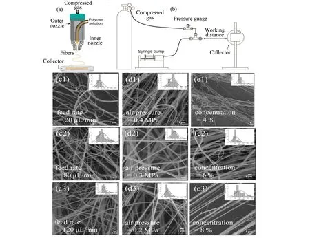
Fig.4 (a) Schematic illustration for a solution blow spinning device and the concentric nozzles (Reprinted with permission from Ref. [51]. Copyright 2015 American Chemical Society); (b) A general solution blow spinning process diagram with rolling collector (Reprinted with permission from Ref. [52]. Copyright 2009 John Wiley and Sons). Solution blowing PLA nanofibers prepared with different (c) feed rate, (d) gas pressure and (e) concentration of the feed solution (Reprinted with permission from Ref. [54]. Copyright 2011 John Wiley and Sons)
Generally, both MB and SB spinning can be defined as the blow-spinning method. Compared with electrospinning, blow-spinning allows a higher fiber productivity benefited from the superior efficiency of the high-speed gas. In addition, the blow-spinning driving force is only supported by the nozzle. Consequently, the properties of the collector substrates do not have any effect on the nanofibers. The DCD influences the nanofibers diameter and the areal density of the obtained network.
2.4 Centrifugal Spinning
Instead of electrostatic force and air dragging force,centrifugal spinning (CS) prepares nanofibers with centrifugal force. CS was first reported in 1924[55]and then widely used for producing micro glass fibers in industry. Nowadays, CS is also called jet-rotate spinning[56]and force spinning[5, 57-59], which is widely used as cotton candy machine. The setup of CS usually includes a rotator with a spinneret and a collector, as illustrated in Fig. 5(a)[60]. During the CS process, the polymer solution or melt ejected from the spinneret, which is provided with centrifugal force by the rotator and becomes jet. With centrifugal force and air frictional force, such jet is elongated and forms a fiber. Eventually the fiber is collected by the collector[3]. The parameters that affect the diameter of centrifugal spun PNFs have been established by previous reports. For example, it was found that the viscosity of solution (polymer concentration), feed rate (capillary number), and centrifugal force (rotation speed) play important roles in the morphology of obtained fibers (Fig. 5(b))[56]. Moreover, the design of the spinneret including diameter, length, and structure is also important to the diameters and morphology of fibers[61]. The formation mechanism of centrifugal spun PNFs have been studied by simulation and modeling[62].As a result, with necessary parameters such as viscosity, feed rate, rotating rate, and the distance between spinneret and collector, the diameter of fiber can be theoretically calculated[63]. In industry, large production scale CS machines for PNFs have been developed by Lozano and Sarkar, and commercialized by FibeRio Technology Corporation[64]. So far, various PNFs have been successfully fabricated by CS with polymer solutions and melts, such as polyepoxyethylene (PEO)[5, 56, 58, 65], PLA (Fig. 5(c))[56, 60], PS[66], PMMA[67], poly-ε-caprolactone (PCL)[59], PVDF (Fig. 5(d), (e)[57], and polyacrylic acid (PAA)[56].

Fig. 5 (a) Schematic illustration of a centrifugal spinning setup (Reprinted with permission from Ref[60]. Copyright 2017, American Chemical Society)[60]; (b) Influence of the capillary number, polymer concentration, and rotation speed on the PNFs’ morphology. The scale bars are 20 μm(Reprinted with permission from Ref. [56]. Copyright 2010, American Chemical Society); Centrifugal spun of (c) PLA[56], and (d) PVDF nanofibers (Reprinted with permission from Ref.[57]. Copyright 2012, John Wiley and Sons); and (e) Diameter distribution of PVDF fibers[57]
Obviously, CS has many advantages, such as high production yields, environmental friendliness, and lower required voltage. Furthermore, with the high efficiency resulted from the high-speed centrifugal force, CS achieves superior fiber productivity. Nanofibers produced by CS are more aligned but with wider diameter distribution compared with electrospinning.
3 Applications
Nowadays, nanofibers have been used in several commercial products. Statistics show that the global market for nanofiber-based products will reach nearly 2.0 billion US Dollars in 2020[68]. The current and emerging applications of nanofibers in different fields have been summarized in Fig.6. Herein, some of the applications based on PNFs are briefly discussed: environmental improvement and protection (i.e., ultrahigh air filtration)[69], biomedical applications (i.e., drug delivery system and tissue engineering)[70], and some other applications including battery separators (e.g., lithium-ion batteries)[71-72]and smart textiles (e.g., sensors and stimulators).

Fig. 6 Emerging applications of nanofibers technology in different fields
3.1 Environmental Improvement and Protection
The environmental applications of functionalized PNFs have been intensively studied, including filtration[73], self-cleaning[74-75], adsorbents[6, 76], oil-spill cleanup[77], and so on. In this section, the focus is on the application of PNF-based materials in the field of air filtration. Currently particulate matter (PM) in air pollution as a serious environmental issue is attracting worldwide attention[78-79]. PM is a mixture of solid particles and liquid droplets of small size floating in the air. PM with particle size of 2.5 μm(PM2.5) or bigger is highly harmful to human health since it is small enough to penetrate the alveoli in the human lungs and reach the circulatory system[80]. Recently, it has been demonstrated that the PNFs can be used as an excellent PM filter because of their outstanding properties. Besides, PAN, PA6, and polyimide (PI) have shown stronger affinity to PM when compared with the conventional PNFs (PP) in commercial filters[81-83]. Moreover, the membranes of PAN showed a higher removal efficiency than PM2.5 and PM10 when compared with PVP, PMMA, and PA66 counterpart membranes. In 2017, Khalid et al.[81]reported a blow-spinning technique, which enables PNFs to be directly coated onto a window screen and protects people from indoor PM pollution (Fig.7(a)-(b)). In this study, commonly available polar polymers (e.g., PAN, PVP, PMMA, PA66) were used to prepare filtration films with a solution spinning setup. All prepared filtration materials were not only fine with high optical transparency, but also did not display prominent damage on both sides of the nanofibers’ morphology after a rolling test (Fig.7(c), (d)). For such materials it is possible to tune their transparency by simply adjusting the deposition time, and PAN exhibited the best filtration performance towards the removal of PM2.5 with an efficiency of over 99% and high transmittance of 80% (Fig.7(e), (f)). Such method enables industrial production with a roll-to-roll form. Based on the high thermal stability, PI nanofibers were able to remove more than 99.5% PM2.5 and the temperature was over 400 ℃, which indicated their application for hot gas filtration.Furthermore, such nanofibrous membranes could be coated on the window screen for air filtration application.

Fig.7 Nanofibers prepared by solution blowing for air filtration: (a)-(b) preparing, (c)-(d) optical and mechanical performance, (e)-(f) filtering performance
Additionally, to prevent the spread of respiratory infectious diseases, wearing masks with PNF filtration materials is an easy and effective method. In order to effectively trap these bacteria and viruses, such materials are normally charged, so that the charged small particles will be trapped when passing through filtration materials. To ensure long term high filtration efficiency, hybridization is often the answer. For example, Yu et al.[82]used the melt blowing technique to prepare PP-based filtration materials which are hybridized with tourmaline particles. In practical applications, it is found that the filtration efficiency was greatly improved. The optimized sample was able to retain over 90% of the pollutant for more than 180 days.
3.2 PNFs for Biological Application
Nanofibers are particularly desirable for applications in drug delivery, burn and wound care, tissue engineering, blood purification, and treatment of various diseases. The nanofiber with high surface area increases the adhesion of cells, proteins, and drugs while providing cost-saving lightweight devices[83]. In this section, some of the most popular biomedical applications of nanofibers are briefly described, which include the drug delivery and tissue engineering scaffold (Fig. 8).
3.2.1Drugdelivery
The potential use of nanofiber for drug delivery has been investigated using small organic drugs and macromolecules. Various bioactive molecules have been incorporated in the bulk phase of electrospun nanofibers or on their surfaces by nanofiber post-treatment[84], immobilization of drug-loaded nanocarriers on nanofibers[85-86], loading drug on the surface of nanofibers by adsorption (such as layer-by-layer multilayer assembly)[35-36], co-electrospinning of drug-polymer compounds[7], and coaxial/emulsion electrospinning[35-37, 87]. Among them, coaxial electrospinning is wildly used for drug incorporation owing to its simplicity (without post-fabrication processing) and relatively low-cost.
For example, loading drugs by multiple approaches on nanofibers would achieve a better performance. Cheng et al.[35](Fig. 8(a)-(c)) prepared a dual drug release system which enabled release controlled by time for bone regeneration, which was achieved with a layer-by-layer assisted coaxial electrospinning method as shown in Fig.8(a). In such core-shell structured nanofibers (Fig.8(b)), bone morphogenetic protein 2 (BMP2) was loaded into the core of the nanofibers by coaxial electrospinning, while the connective tissue growth factor (CTGF) was loaded onto the surface with the layer-by-layer approach. As shown in Fig.8(c), CTGF presented a fast release while BMP2 exhibited a sustaining release, which was conducive for bone tissue recovery. Furthermore, such drug release system could be used in vivo as a scaffold, which indicates a promising strategy to facilitate bone healing.
3.2.2Scaffoldsfortissueengineering
Tissue engineering approaches typically require scaffolds, cells, biochemical cues (i.e., growth factors), and mechanical stimuli to create functional tissues. Compared with traditional implant/biomaterial surfaces, nanofiber scaffolds with a nanofibril framework are an exceptional system that is able to mimic the corresponding natural human tissue design at nanoscale[88]. The small diameter of nanofibers closely matches that of natural extracellular matrix fibers, and its relatively large surface area also favors cell attachment and bioactive factor loading[89]. Furthermore, various bioactive agents can be incorporated into nanofibers achieving the optimal concentration and diffusion. In restorative surgery, nanofibers are used as scaffolds for the tissue engineering of skin, musculoskeletal (bone, cartilage, ligaments) and neural tissues[90]. Engineering living tissues for reconstructive surgery requires an appropriate cell source, optimal culture conditions, and a biodegradable scaffold. A variety of natural (gelatin[91], collagen[92-93], and elastin[93]) and synthetic (PCL[8, 94-96], PLA[97-98], PU[99], poly (lactic acid-co-ε-caprolactone) (PLCL)[100]and poly(lactic-co-glycolic acid) (PLGA)[101-102]) bridgeable polymers have been electrospun into nanofibers for tissue engineering applications. The choice of the most suitable drug/polymers combination for surface modification with bioactive molecules[103-104]or decellularized tissue[8, 94]and the control of the nanofiber diameter[102]and alignment[96-97]can provide a blueprint for engineering specific tissues[105].
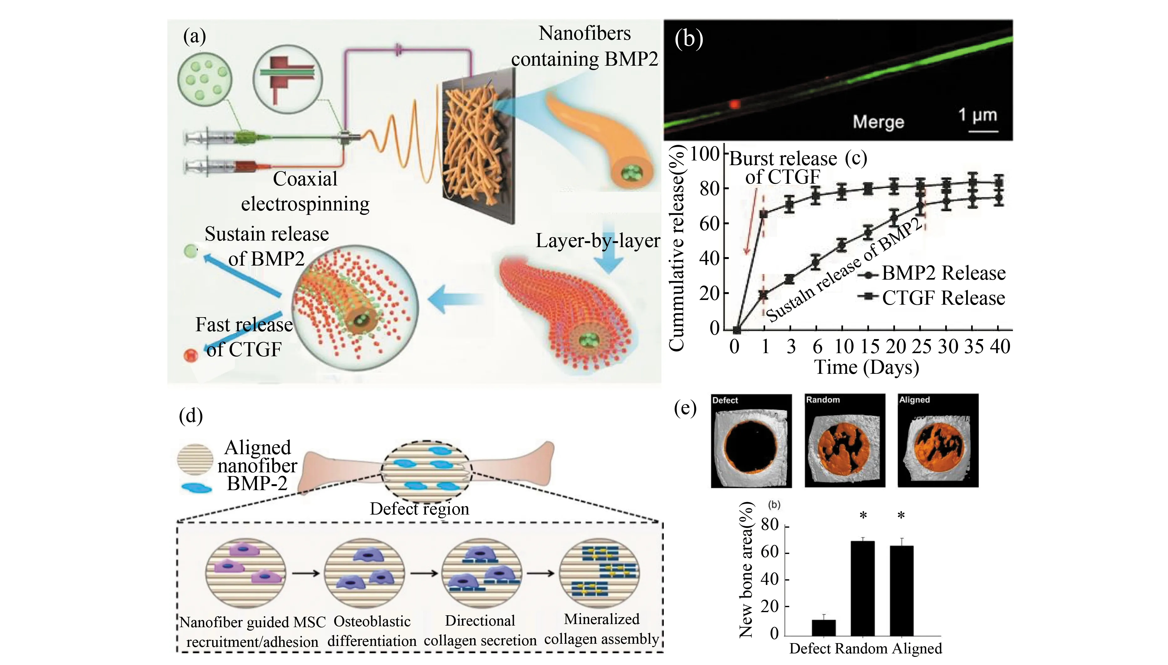
Fig. 8 Schematic illustration of various techniques to produce nanofibers for biological applications: (a-c) nanofibers prepared by coaxial electrospinning combined with layer-by-layer self-assembly strategy for drug delivery (Reprinted with permission from Ref. [35]. Copyright 2019, American Chemical Society); (d-e) nanofibers with aligned structure and surface modification for tissue engineering applications (Reprinted with permission from Ref. [106]. Copyright 2015, American Chemical Society)
Scaffolds with aligned structure were generally used in tissue with oriented structure, such as tendon and vessel. As shown in Fig. 8(d), Perikamana et al.[106]prepared a scaffold with aligned structure and surface modified with BMP2 for bone tissue engineering. As a result, implanting of such scaffolds facilitated the bone regeneration, while there was no significant difference between scaffolds of random and aligned structure(Fig.8(e)). However, the Young’s modulus and contact hardness of regenerated bone implanted with aligned scaffold presented anisotropic feature compared with random scaffold.
To better mimick native tissue, decellularized materials are commonly used for tissue engineering in recent years. However, decellularized materials always exhibit poor mechanical properties. Preparing nanofibers reinforced decellularized materials as a scaffold is a promoting method. Zhou et al.[94]prepared such a scaffold by electrospinning PCL nanofibers on decellularized amniotic membrane (dAM) for ocular surface treatment. The dAM provided the scaffold with anti-inflammatory efforts and inherent pro-regenerative properties, and PCL nanofibers improved the mechanical properties (e.g., tensile strength, toughness, and suture retention strength). As a result, the implanting of such scaffold facilitated the re-epithelialization of the defect tissue, and attenuated inflammation and neovascularization.
3.3 Other Applications
3.3.1Separatorforbatteries
In this century, one of the most important topics in the energy field is to create and store renewable energy with highly efficient and environmentally friendly methods[107-109]. For example, lithium-ion battery (LIB) is a highly efficient power with the properties of high energy densities, low self-discharge rate, and no memory effect[110], and its long cycle life results in less damage to the environment. Moreover, LIB exhibits high operational voltage, which enables its wide applications[111]. LIBs mainly consist of anode, cathode, separators, and electrolytes. It has been demonstrated that nanofibers play an important role as a battery separator for optimizing ionic and electronic conduction pathways as well as blocking undesired and irreversible side reactions[112]. Its properties of nano-size, high porosity, and specific surface area as well as the designable pore structure enable nanofibers to be high electronically and ionicly conductivity, which enhanced the cyclability and rate capability of LIB[113]. Huang et al.[114]reported a coaxial electrospun cellulose acetate / PVDF-HFP nanofibrous membrane for LIBs battery(Fig. 9(a)). The shell of PVDF-HFP presented high porosity and uptake of electrolyte, and the core of cellulose acetate provided mechanical properties for the composite membrane. As aseparator for LIB, such membrane was punched into discs to form LIB. As a result, such membrane present good tensile strength (34.1 MPa), high porosity (66%), excellent thermal stability (to 200 ℃), and super electrolyte compatibility (355% electrolyte uptake) (Fig. 9(b))[114].
3.3.2Functionalmaterialsforsmarttextile
Through various hybridization strategies, PNF-based textiles and fabrics possess multifunctional properties and have promising applications as cooling materials, conductive textiles, communicating textiles, sensors and actuators, digital fashion, and chromatic textiles[115-116]. The high porosity and small pores of nanofiber mats offer good resistance to harmful chemical aerosols. Nanofiber technology enables the improvement of the fabric performance (e.g., anti-bacterial properties, detoxification capability, waterproofing, and breathability). For clothing, it is also important to be able to add different colors to the fabric. Colored solution electrospinning has been used to fabricate colorful and visually appealing nanofiber fabrics with various functionalities. In this means, powdered dyes can be dissolved or dispersed in the electrospinning solution or in the preformed polymer to produce stained nanofibers by electrospinning[117]. The as-spun colored fabrics and membranes have excellent level-dyeing properties and color stability. For instance, Yan et al.[118]prepared polyvinyl butyral/cationic dye membranes by electrospinning (Fig.9(c)), which presented good color uniformity and high hydrophobicity(Fig.9(d),(e)). Such colored nanofibers could be directly electrospun onto Al foil, wall, and fabrics (Fig. 9(f)), which indicates its potential applications for waterproof textiles, wallpapers, and anticorrosive coating/painting. However, this technique is complex and inefficient, particularly in the case of nanofibers with high surface area and high light scattering ability[119-120].
4 Conclusions and Prospects
Methods for preparing continuous nanofibers, electrospinning, melt blowing, solution blowing, and centrifugal spinning are introduced above, which elongate fibers to nano-size with electrostatic force, air dragging force, and centrifugal force, respectively. Among these methods, electrospinning is the most commonly used in laboratory due to its simple and cheap lab-scale setup, while melt blowing is widely used in industries owing to its high production rate. As a new technology for preparing PNFs, centrifugal spinning shows its capability and feasibility in producing PNFs with high speed and low cost, but problems such as the wide diameter distribution of PNFs and the continuous collecting for nanofibers need to be solved. In addition, preparing PNFs with melted polymer is more popular with industries because being free of solvent is environmently friendly and low cost. However, it is limited to a few polymers (e.g., PP, PBT, PS) and the obtained PNFs are thicker than PNFs prepared with solutions.
With outstanding properties of both nano-sized material and fiber, nanofibers is a promising material for various applications. Beside the inherent properties of nanofibers (e.g., large specific surface area, characteristically different physical and chemical properties, flexibility), PNFs can be endowed with new functions by hybrid approaches. With such advantages, PNFs are widely used in environmental improvement and protection, biological application, energy field, smart textile, and so on. Many examples of PNFs in such applications are summarized above, which indicate nanofibers will be more advanced when combined with hybrid technology. Above all, with the development of PNF fabricating technologies,multifunctional or intelligent PNFs will be large scale produced in the future.
JianLuis a Ph.D. student at the College of Material Science and Engineering and the State Key Laboratory for Modification of Chemical Fibers and Polymer Materials (SKLFPM) at Donghua University. His research focuses on the preparation and biological applications of fiber materials.

Dr.ZexuHuis a postdoctoral fellow at the College of Material Science and Engineering and the State Key Laboratory for Modification of Chemical Fibers and Polymer Materials (SKLFPM) at Donghua University (DHU). He obtained his Ph.D. degree from the College of Materials Science and Engineering, DHU. His research focuses on the preparation and industrialization of melt-spun fibers.

Dr.QianqianWangis a postdoctoral fellow at the College of Material Science and Engineering and the State Key Laboratory for Modification of Chemical Fibers and Polymer Materials (SKLFPM) at Donghua University (DHU). She obtained her Ph.D. degree from the College
of Materials Science and Engineering, DHU. Her research focuses on the formation of bio-based fibers and preparation of bio-based hydrogels.

Dr.MatteoCiprianobtained his M.S. degree in Industrial Chemistry from the University of Padua, Italy in 2012, after performing his research work at Solvay Headquarters in Brussels, Belgium. Afterwards, he spent a year at the Ghent University, Belgium working in close partnership
with BASF and The Energy Research Center of The Netherlands for the development of a natural polymer-based heat pump. In 2019, he received his Ph.D. degree from the State Key Laboratory of Advanced Technology for Materials Synthesis and Processing, Wuhan University of Technology, China on zeolitic imidazolate frameworks under the supervision of Prof. Francis Verpoort. He is currently a postdoctoral fellow at Donghua University, working in collaboration with Prof. Meifang Zhu on the development of multi-functional materials for advanced electronic applications.

Dr.XiangFeiis an assistant professor at the College of Material Science and Engineering and the State Key Laboratory for Modification of Chemical Fibers and Polymer Materials (SKLFPM) at Donghua University (DHU). He obtained his Ph.D. degree from Fudan University in
2013. Prior to joining DHU, he worked as a postdoctoral fellow at the University of Zurich from 2013 to 2016, and as a research fellow at the National University of Singapore from 2016 to 2018. His research focuses on rational design and preparation of smart polymer fibers and fabrics.
杂志排行

Journal of Harbin Institute of Technology(New Series)的其它文章
- γ-Fe2O3@carboxymethyl Cellulose as Potential Oral Nanomedicine for Iron Deficiency Anemia Treatment on Rats
- Evolution Toward Artificial Intelligence of Things Under 6G Ubiquitous-X
- Investigations about the Atomic Structure and Mechanical Behavior of Metallic Glasses after Melt Hydrogenation
- Review: Layer-Number Controllable Preparation of High-Quality Graphene for Wide Applications
- Review: Research Progress for Electric Vehicle Hub Motor Driving Technology
- Review:Chromatic Dispersion Manipulation Based on Optical Metasurfaces