Controlled Movements in Superlubric MEMS
2020-07-16CangyuQuXiaojianXiangMingMaandQuanshuiZheng
Cangyu Qu, Xiaojian Xiang, Ming Ma and Quanshui Zheng, , 4 *
(1. Institute of Superlubricity Technology, Research Institute of Tsinghua University in Shenzhen, Shenzhen 518057, Guangdong,China;2. Center for Nano and Micro Mechanics, Tsinghua University, Beijing 100084, China;3. State Key Laboratory of Tribology & Department of Mechanical Engineering, Tsinghua University, Beijing 100084, China;4. Department of Engineering Mechanics, Tsinghua University, Beijing 100084, China)
Abstract: Structural superlubricity (SSL) refers to a state where the friction and wear between two directly contacted solid surfaces are virtually zero. The realization of microscale SSL in 2012 rapidly explored SSL technologies which hold great potential in the development of reliable and energy-efficient micro devices. A key to a successful superlubric device is to control the movements of the superlubric slider. To solve this challenge, here two general principles are shown to guide and control the motion of the slider, i.e., by minimization of interfacial energy and minimization of electrostatic energy. When the shapes of the slider and substrate are designed appropriately, the excess interfacial energy of the contact-pair provides restoring and constraining forces to the slider. Similarly, tunable driving and constraining forces are enabled by the electric fields induced by the electrodes buried in the substrate. These concepts are demonstrated on the design of a superlubric resonator whose natural frequency of the lateral translational mode is well-defined and unfavorable rotation is constrained. The above design principles should be applicable to superlubric devices in general and help the development of future applications of structural superlubricity.
Keywords: structural superlubricity; MEMS; resonator; controlled movement
1 Introduction
Friction and wear are interfacial phenomena commonly observed not only in daily life but also in many important fields of industry. Their effects are significantly enlarged due to the large surface-to-volume ratio when the system size reduces to micrometer scale, and have become bottlenecks that hinder the development of reliable and energy-efficient microelectromechanical systems (MEMS). Structural superlubricity (SSL) offers a unique solution to this challenge since its first realization on microscale[1-3]based on earlier theoretical predications and experimental attempts[4-6]. It refers to a state of nearly vanishing friction and wear due to systematic cancellation of lateral forces acting on each atom, when two solid surfaces are in incommensurate contact. One of the most promising application fields of microscale SSL is MEMS[7-10]. The control of friction and minimization of wear are important aims within the MEMS regime, especially in devices where relative motion of contact-pairs is involved[11]. Ultralow friction and wear can be achieved in superlubric contacts without adding any lubricants. This feature not only provides a friction reduction scheme to the existing MEMS, but also inspires disruptive designs of novel nano- and micro-devices. Since the theoretical prediction of superlubricity in 1980s to 1990s[4-5], superlubricity was only achieved on nanoscale under strict conditions in early experiments[6]. Meanwhile, pioneering works on the retraction and oscillation motion of van der Waals (vdW) layered materials attracted intensive research interest of using vdW materials for the moving parts in MEMS/NEMS for their ultralow friction[7-9,12-13]. The gigahertz oscillator proposed also became the first concept of nano-device that utilizes the ultralow friction of vdW materials[9]. The first observation of microscale SSL in graphite[1, 10]bridged the two parallel paths of fundamental studies on superlubricity and micro/nanoscale mechanical devices based on vdW materials. SSL technologies were made possible. From then, a lot of fundamental researches on microscale SSL have been conducted on graphite mesas[2-3, 14-16], as well as the heterojunctions between a graphite mesa and another material[17-21]. While on the other hand, SSL based micro-devices with versatile functions were designed or conceptually proved, such as SSL generator[22]and SSL oscillator[23]. Some of the milestones in the history of microscale SSL and SSL MEMS/NEMS are summarized in Fig. 1 and discussed in Supplementary Materials.

Fig. 1 Microscale SSL and SSL MEMS/NEMS. For SSL MEMS/NEMS (top row, from left to right), works listed here include the observation of self-retraction phenomenon of carbon nanotubes (Reprinted with permission from Ref. [7]. Copyright 2000, The American Association for the Advancement of Science), carbon nanotube gigahertz oscillator (Reprinted with permission from Ref. [9]. Copyright 2002, The American Physical Society), self-retraction phenomenon of microscale graphite mesas (Reprinted with permission from Ref. [10]. Copyright 2008, The American Physical Society), the design of a superlubric generator (Reprinted with permission from Ref. [22]. Copyright 2020, Elsevier), and the observation of oscillation motion in graphite mesas (Reprinted from Ref. [23]). For microscale SSL (bottom row, from left to right), works listed here include the theoretical prediction of superlubricity concept[4-5] (Reprinted with permission from Ref. [24]. Copyright 2013, The American Physical Society), the nanoscale validation of superlubricity (Reprinted with permission from Ref. [6]. Copyright 2004, The American Physical Society), the observation of microscale superlubricity (Reprinted with permission from Ref. [1]. Copyright 2012, The American Physical Society), robust superlubricity on heterojunctions (Reprinted with permission from Ref. [17]. Copyright 2018, Springer Nature), the Nature perspective on SSL (Reprinted with permission from Ref. [3]. Copyright 2018, Springer Nature)
An important challenge for the implementation of superlubric MEMS device is the difficulty in controlling the movement of a superlubric contact. In a superlubric contact, the slider has two in-plane translational degrees of freedom (xandy), and one in-plane rotational degree of freedom (θ). The slider can usually move in a large domain in the (x,y,θ) phase space. Meanwhile, the interfacial friction is ultralow, since it is superlubric. Thus external perturbations and imperfections of the structure itself can have significant disturbance on the movement of the slider[19, 25-28]. Therefore, for the functioning of superlubric device, it is essential to guide the motion of the slider in a controllable way and maintain the contact in the low-friction superlubric state. Mechanical supports such as clamps are often used to constrain the motion of the deformable part in conventional MEMS. However, this is usually not feasible in superlubric contacts. Instead, methods with alternative physical principles have to be developed. Experiments have shown that the interfacial energy of the superlubric contact-pair itself can be utilized to drive the motion of the slider[10,14,29]. Recently, a rotational instability was reported on graphite mesas, where the interfacial energy constrains/drives the rotation of the slider before/after a critical displacement[27]. In the constraining regime, the interfacial energy self-aligns the sliding contact. Meanwhile, electrostatic forces have been widely used in MEMS for its simplicity, high energy density, and compatibility with fabrication process. Parallel-plate and comb-drive are commonly used for electrostatic actuators[30]. It would be interesting to explore the possibility of using these two principles for controlled movements of superlubric MEMS.
This work shows that controlled movement of a superlubric MEMS is possible by utilizing interfacial energy and electrostatic force. When the shape of the contact-pair is designed appropriately, the interfacial energy of the contact-pair provides restoring and constraining forces to the slider. Extra driving and constraining forces are enabled by the electric fields induced by the electrodes under the slider. These two principles are demonstrated on the design of a superlubric oscillator. With the application of the design concepts, the oscillator shows a well-defined resonance frequency in the lateral translational mode, which is crucial for its practical use as a resonator. The unfavorable movements in other degrees of freedom (including rotation and translation) caused by external perturbations can be constrained. The design principles presented here should be applicable in general to superlubric devices and help the improvements of existing superlubric devices and the development of new ones. In the following part of this paper, the basic concept of superlubric MEMS are first described in Section 2. The two principles of controlling the movements of the slider in a superlubric MEMS device, i.e., the minimization of interfacial energy and the minimization of electrostatic energy, are detailed in Section 3 and Section 4, respectively. Conclusions are given in Section 5.
2 Concept of Superlubric MEMS
Before discussing the principles of controlled movement in superlubric MEMS, in this section, the basic concept of a superlubric MEMS and how it works are shown, by taking the superlubric oscillator as an example and comparing it with a conventional MEMS resonator.
Fig. 2(a) shows the simplified working principle of a conventional MEMS cantilever resonator actuated by electrostatic method. The oscillating part is typically a mechanically supported elastic body generating restoring force. The support anchor offers the constraints to the elastic beam while limits the available displacement to a certain extent at the same time. When the elastic response is in the linear regime, the oscillator is harmonic and has a well-defined resonance frequency. In this case, this oscillator acts as a resonator. Different from the conventional design, the design of a superlubric resonator is proposed in Fig. 2(b). The oscillating part is a slider which slides on a substrate, and the contact between the slider and substrate is superlubric. The substrate is made of an insulator, thus acting as an insulation layer at the same time. Thanks to superlubricity, the friction and wear of this sliding interface can be virtually zero. Interfacial energy provides both restoring and constraining forces to the slider, while driving forces are provided electrostatically, as will be detailed later in this paper. Compared with the elastic beam, the superlubric oscillator does not depend on the clamped anchor to generate restoring force, and the slider can move in a large range. As a result, the oscillation amplitude of the superlubric slider can be large compared with the elastic beam whose oscillation amplitude is essentially limited by the small amount of elastic deformation that the material can sustain.

Fig. 2 Conceptual sketches showing the simplified working principles of a conventional MEMS resonator and a superlubric oscillator. The top and bottom panels are side and top views, respectively. (a) In a conventional MEMS resonator, restoring force is provided by the elastic force of an elastic body (blue), and the actuation electrodes are colored yellow; (b) In a superlubric oscillator, restoring and constraining forces are both applied by the interfacial energy of the slider (blue) and the substrate (gray); while same actuation principles as conventional MEMS are used (here as an example, electrostatic force, as colored in yellow)
3 Interfacial Energy
3.1 Principles
The effect of interfacial energy in a general superlubric contact can be understood by the kinematic model shown in Fig. 3. The model consists of a stationary substrate and a rigid but movable slider. The contact between the slider and the substrate is superlubric. The movable slider has three degrees of freedom, i.e., two translational ones,xandy, and the rotation in thexoyplane,θ. In a general case, the slider and substrate can be made from two different materials, whose specific surface energies areγ1andγ2, respectively. Considering that the contact between the slider and substrate has a variable contact areaA, the excess total interfacial energy is
Us=U0+(γint-γ1-γ2)A=U0-ΓA
(1)
whereU0is a constant reference value,γintis the specific interfacial energy of the slider-substrate contact interface, andΓ=γ1+γ2-γintis defined as the cleavage energy of this contact[14,29]. Eq. (1) implies that the system always tends to acquire the largest contact area as possible, in order to minimize the total interfacial energy.
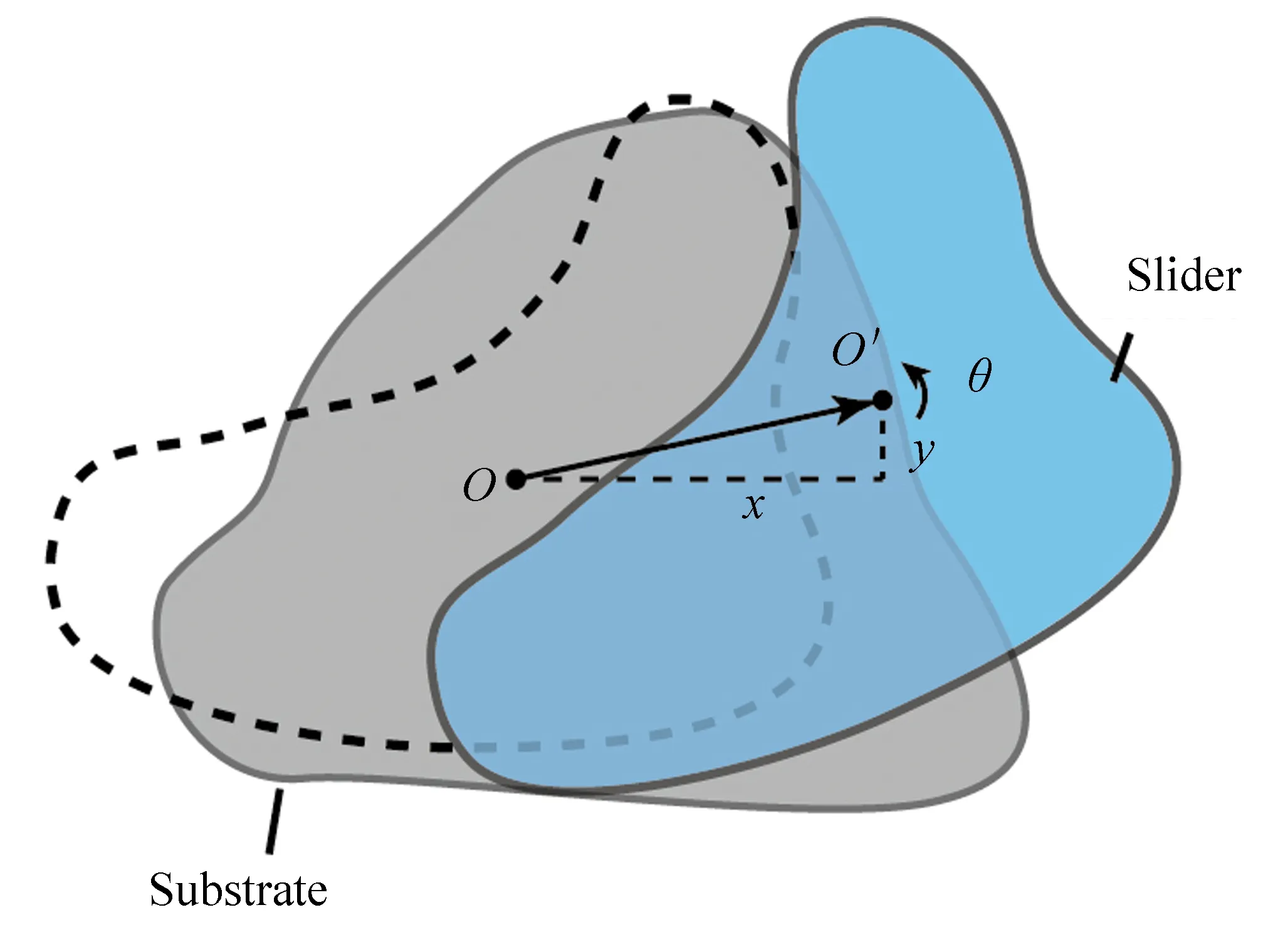
Fig. 3 Kinematic model of a general superlubric joint (top view). The model consists of a stationary superlubric substrate and a rigid but movable superlubric slider. The excess total potential energy Us is a variable dependent on the contact area A, which is in turn determined by the displacements of the slider, x and y, and the in-plane rotation, θ
As a result, the generalized forces induced by interfacial energy are
(2)
whereqi=x,y,θare the generalized coordinates. The generalized forcesQicorresponding to the generalized coordinatesqieither constrain or drive the displacement/rotation of the slider, depending on the geometry and loading cases.
3.2 Design of Slider Shape
As a demonstration, in this subsection, the general principles described above is applied to the design of slider shape in a superlubric oscillator. Four candidate designs, including one widely considered in previous studies, are investigated. We will show that, through appropriately designing the shapes of the slider and substrate, it is possible to develop a superlubric resonator with a well-defined resonance frequency on the order of 1 MHz, and the unfavorable rotation of the slider can be constrained for oscillating amplitude up to 1 μm.
3.2.1Linearrestoringforce
For practical use as a resonator, an oscillator should have a well-defined resonance frequency, which requires a linear relation between the restoring force and displacement. The restoring force in a superlubric oscillator is provided by the retraction force induced by interfacial energy. Following Ref. [10], the retraction force is defined as
(3)
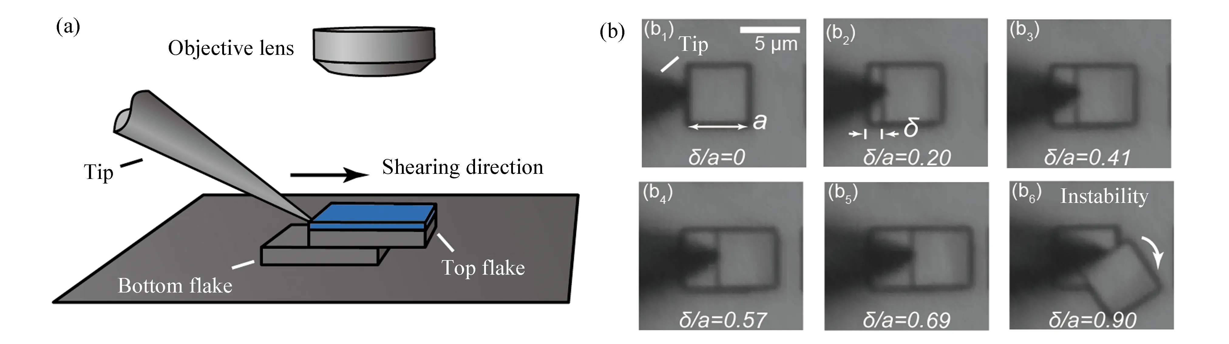
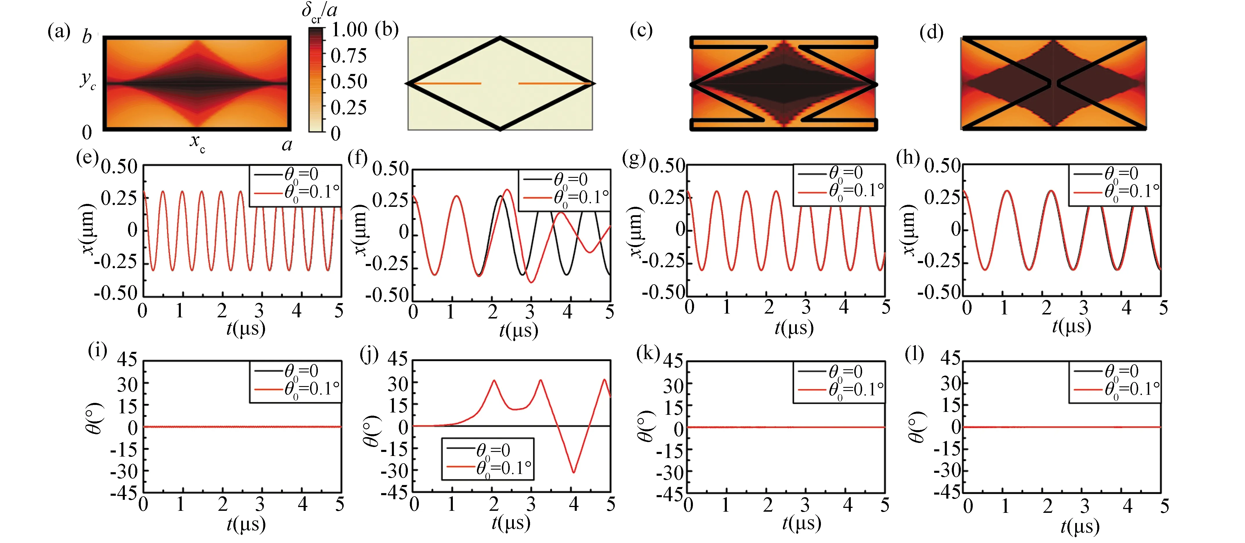
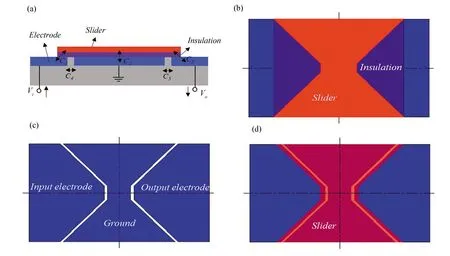
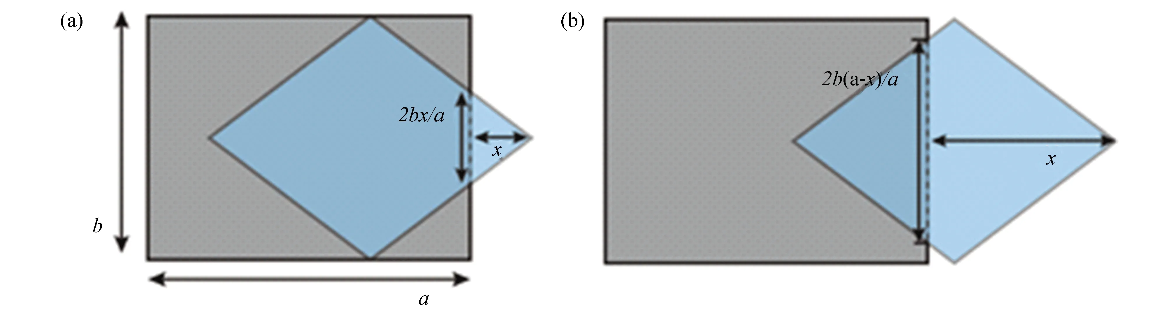
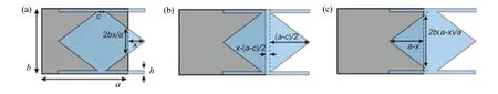
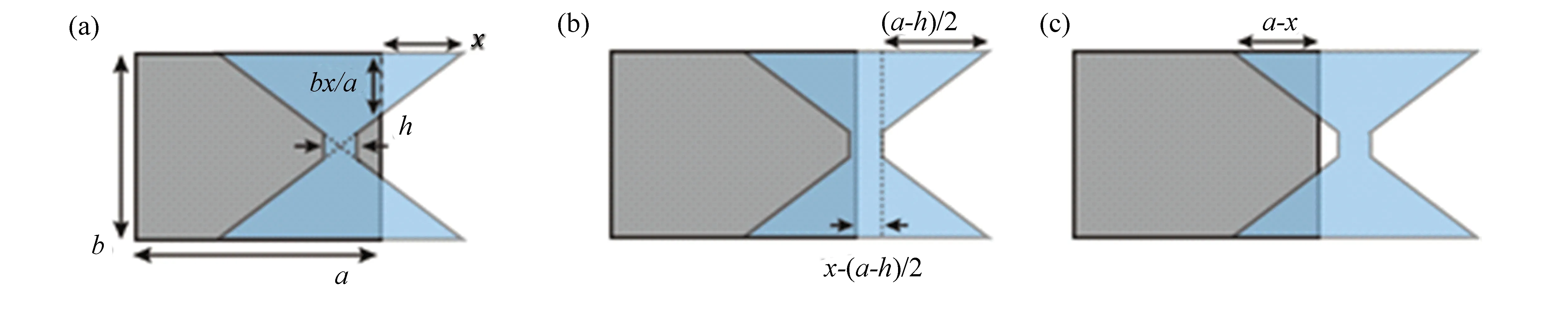
In previous works, rectangular sliders were used, as shown in Fig. 4(a). The retraction force is a step function as shown in Fig. 4(e)[10,29]. In this case, theFret-xrelation is non-linear, and the frequency of the oscillator depends on its oscillating amplitude. To solve this problem, a structure with rhombus shaped slider and a rectangular substrate is designed (denoted as the 2nddesign), as shown in Fig. 4(b). In this case, the retraction force is linear for -a/2 (4) whereρis the mass density of the slider,tis the slider thickness, andais the slider length shown in Fig. 4(b). Despite the linearFret-xrelation, it will be shown later that this structure cannot sustain a translation-only movement. The slider rotates spontaneously when it starts to move. It has been indicated that the rotational stability is sensitively dependent on slider shape[27]. Therefore, two different designs (denoted as the 3rdand 4thdesigns) are proposed, as shown in Figs. 4(c) and 4(d). For the 3rddesign, the retraction force is step-like atx=0, but linear for 0<|x|<(a/2)(1-2h/b). TheFret-xresponse of this design is non-linear, however, the step size is dependent on the width of the bar-shaped segments on the slider,h, asΔFret=4Γh. Whenhis small, theFret-xcurve can be regarded as approximately linear. For the 4thdesign, theFret-xresponse is linear in the range of -(a-h)/2 For the 2ndand 4thdesigns, the resonance frequency can be estimated by Eq. (4). For a graphite slider-substrate, the cleavage energyΓis on the order of 0.2 J/m2[14,29,31]. With the typical values of geometry parametersa=5 μm andt=100 nm, the frequency is estimated to be on the order of 1 MHz. Fig.4 Four designs of the superlubric oscillator and their corresponding Fret-x curves. (a)-(d) Sketches of the four designs. The substrates (grey color) are rectangles in all the designs, while the sliders (blue color) have different shapes. (e)-(h) Fret-x curves corresponding to the four designs. It is shown that the restoring force in the 1st design is nonlinear (step-like) at x=0; the 2nd design is linear when -a/2 3.2.2Rotationalstability Other than the requirement of a linearFret-xrelation, the slider has to be rotationally stable. A recent research showed that the interfacial energy can drive the slider to suddenly rotate at a certain critical displacementδcr, and the rotation usually leads to irreversible destruction of the superlubric interface[27]. Optical microscopic snapshots of an experiment showing such an instability is presented in Fig. 5. Such rotation must not happen for a reasonable range of displacement where the superlubric oscillator is designed to work in. Following the algorithms developed in Ref. [27], assuming that they-direction translation of the slider is constrained, i.e., onlyx-translation and rotationθis permitted, the critical displacementδcris found dependent on the rotation center (xC,yC). Aδcr-contour on the (xC,yC) plane is drawn for each of the 4 designs described above, as shown in Figs. 6(a)-(d). Higherδcrindicates that the slider can move without any rotation for a larger displacement in thex-direction. For the 1st, 3rd, and 4thdesigns, it is found thatδcris always larger than 0.3a, which is 1.5 μm fora=5 μm, regardless of the rotation center. This result implies that the interfacial energy can effectively constrain the rotation of the slider when its oscillating amplitude is smaller than 1.5 μm. On the other hand, the situation is completely different for the 2nddesign. Non-zeroδcris found only when the rotation center is located exactly on the centerline of the slider, i.e.,yC=0. Otherwise, the critical displacement is zero, which implies that the slider will rotate immediately as it starts to move. The conclusions from theδcr-contours are further confirmed by fully dynamic simulations considering all the 3 degrees of freedom of the slider (i.e.,x,y,θ). The simulation was conducted by solving the Lagrange’s equations with the potential energy given by Eq. (1). Two runs were carried out for each design. In the first run, the initial conditions (denoted as #1) are defined asx(0)=0.3 μm,x'(0)=0,θ(0)=θ'(0)=0,y(0)=y'(0)=0. This set of initial conditions corresponds to the scenario that the slider is displaced for 0.3 μm inx-direction and then released free. In the second run (denoted as #2), a perturbation is applied asθ(0)=0.1°, and the rest of the initial conditions are the same as #1. The results of the two runs are plotted in Figs. 6(e)-(l) as the black and red curves, respectively. For the 1st, 3rd, and 4thdesigns, the black and red curves are almost identical, implying that a small perturbation does not influence the system response. Especially, Figs.6(i), 6(k), and 6(l) show thatθ(t) stays atθ(t)≈0, suggesting that the system is rotationally stable. However, the black and red curves are significantly distinct with each other for the 2nddesign, suggesting that the slider is very sensitive to perturbations and a small perturbation in the initial value ofθleads to completely different system response. Fig. 5 Experimental setup and optical microscopic snapshots of the rotational instability phenomenon. (a) Experimental setup. The square mesa is sheared by a tungsten tip and monitored from the top with an optical microscope; (b) Optical microscopic snapshots (top view). The top flake of the mesa is slowly sheared out by the tip. When the displacement (δ) is small, the mesa moves without rotation. While when δ reaches a critical value, the interfacial energy drives the top flake to suddenly rotate, showing an instability. (This figure is adapted with permission from Ref. [27]. Copyright 2019, The American Physical Society) Fig. 6 Rotational stability of the superlubric oscillator with four different designs.(a)-(d) δcr-contours in (xC,yC) plane. Black lines show the shapes of the sliders. All the contours share the same colorbar shown in (a). For the 1st, 3rd, and 4th designs, non-zero δcr suggests that the slider in each design can slide without rotation to a certain distance; while for the 2nd design, δcr=0 for yC≠0, which suggests that the slider rotates very easily. Geometric parameters are a=5 μm,b=0.5a,h=0.1b. (e)-(h)x(t) curves for the four designs starting from two sets of initial conditions,#1: x(0)=0.3 μm,x'(0)=0,θ(0)=θ'(0)=0,y(0)=y'(0)=0 (black curves), and #2: the same as #1 except that θ(0)=0.1° (red curves). (i)-(l)θ(t) curves for the four designs starting from the two initial conditions. For the 1st, 3rd, and 4th designs, the black and red curves are almost identical, suggesting that the system is stable against the perturbation in θ. However, for the 2nd design, the small perturbation in the initial condition leads to significant difference in system response, suggesting that it is rotationally unstable. Combing the results ofFret-xcurves and rotational stability, the 4thdesign is the only one among the 4 designs that meets the design targets for a superlubric resonator. Actuation by electrostatic force is the most widely used method to drive the mechanical motion in MEMS, because of its simple principles, high energy density, and excellent processability. Based on the defined superlubric contact-pair design with linear restoring force and rotational stability discussed above, an electrostatically actuated superlubric resonator is designed in this section. As shown in Fig. 7, the resonator consists of a substrate, three actuation electrodes (in blue), an insulation layer (in purple), and a slider (in red). The superlubric contact-pair is formed by the slider and the insulation layer, and has a linear restoring force characteristic. Three actuation electrodes are symmetrically distributed below the slider. The middle electrode is grounded, and the left and right ends are an input end (Vi) and an output end (Vo) , respectively. It can be seen in Figs. 7(a) and 7(d) that the designed slider covers the grounded electrode entirely, and overlaps with the input and output electrodes by a small area. Therefore, capacitors are formed between the slider and three electrodes, denoted asC1,C2, andC3, respectively. When an external excitation signal is applied on the left, the generated electrostatic force in the horizontal direction will vibrate the slider, and the resulting capacitance variation between the slider and electrodes can be detected by the output end. Fig. 7 The designed superlubric resonator schematic. (a) Front view of the superlubric resonator. It consists of a substrate, three actuation electrodes (in blue), an insulation layer (in purple), and a slider (in red). (b)Top view of the superlubric resonator. (c)Bottom actuation electrode distribution. The left one is an input electrode; the central one is grounded, and the right one is an output electrode.(d)Top view of the superlubric resonator with transparent slider to show the relative position between the slider and electrodes (the insulation layer is not shown for visual clarity). It can be seen that the designed slider covers the grounded electrode entirely, and overlaps with the input and output electrodes by a small area. In the designed superlubric resonator, electrostatic force works as a driving force, and simultaneously a position constraining force to prevent the slider from shifting iny-direction due to external perturbations. To derive the driving and constraining forces, an equivalent circuit of the designed superlubric resonator is shown in Fig. 8. Combining with the energy principle, the electrostatic driving forceFxin thex-direction, and the electrostatic constraining force in they-direction are given as (5) (6) whereUeis the total electrostatic energy, andCais the total system capacitance, which is, according to the equivalent circuit, written as (7) whereC4andC5are the capacitances between the left and central electrodes, and between the central and right electrodes, respectively. The capacitancesC1,C2, andC3are further dependent on the overlapping areas as (8) wherei=1,2,3, andAiis the corresponding overlapping area,0is the permittivity of vacuum,ris the relative permittivity of the medium, anddis the thickness of the insulation layer. Fig. 8 An equivalent circuit of the designed superlubric resonator shown in Fig. 7. Capacitances between the slider and three electrodes are denoted as C1, C2, and C3, respectively. C4 is the capacitance between the left electrode and the central electrode; C5 is the capacitance between the central electrode and the right electrode To quantitatively demonstrate the driving and constraining effects, the driving and constraining forces are calculated for a typical geometry as shown in Fig. 9(a), with a 50 V input voltage applied to the left electrode. When the slider (outlined in red) moves in thex- ory-direction, as shown in Fig. 9(b), the total electrostatic energy and corresponding electrostatic forces are calculated. Inx-direction, the electrostatic energy reaches its minimum atx≈-2 μm, as shown in Fig. 9(c). This result implies that the slider tends to move left, when released from the center. At the position ofx=0, the electrostatic force that drives this movement is on the order of 1 μN, as shown in Fig. 9(d). To estimate the frictional force, it is first noticed that the friction force for a 3 μm square mesa is typically 40-80 nN, and can be reduced to below 30 nN with proper treatment[15]. Assuming that the friction force of the specific design shown in Fig. 9 is on the same order, it can be concluded that the electrostatic driving force is indeed large enough to overcome the friction force between the slider and the substrate. It is noted that the electrostatic force here is nonlinearly dependent onx. In fact, with appropriate design, linear-spring-like restoring force is also possible, which will be detailed in a future publication. Meanwhile, in they-direction, the electrostatic energy minimum is located atx=0, as shown in Fig. 9(e). Thus the slider tends to stay on the middle iny-direction. Anyy-displacement due to external perturbations will be constrained and the constraining force is on the order of 1 μN as well, as shown in Fig. 9(f). The geometric parameters used for calculation area=6 μm,b=3 μm,h=0.5 μm,a=6 μm,c=0.5 μm,g=1.5 μm, andd=20 nm. As a proof-of-concept estimation,r=1 is assumed for all the capacitances. The thickness of the electrodes is assumed to be 50 nm when calculatingC4andC5. In a real device, energy dissipation is inevitable. However, thanks to the ultralow friction of a superlubric interface, the energy dissipation can be very low in a superlubric oscillator whose quality factor can be as high as 1.3×10⁷, as shown in Ref. [23]. Meanwhile, the electrostatic actuation discussed in this section can also supply energy to the system and maintain a sustainable oscillation. In a real device, the non-zero friction at the sliding interface also has effect on the rotational stability discussed in Section 3.2.2. When only friction and interfacial energy are considered, the friction at the interface induces an extra torque that resist any rotation of the slider. Therefore, the friction generally benefits the stability against rotation in this regard. On the other hand, if taking electrostatic actuation into consideration as well, having larger friction means a larger voltage is needed to drive the motion. The rotational stability should be dependent on the total energy (sum of interfacial energy and electrostatic energy) as well as the frictional resistance torque. In this case, the stability is dependent on the specific geometry and design, and a systematic study is left for further research. Fig. 9 Electrostatic energy and driving/constraining forces. (a) Sketch showing the geometry of the slider and electrodes. The sider is outlined in red. (b)Sketches showing the resonator with slider displaced in x- and y-directions, respectively. (c) Ue-x curve shows that the slider tends to move toward the energy minimum located at x=-2 μm. (d)Fx-x curve shows that the electrostatic driving force Fx is on the order of 1 μN. (e)Ue-y curve shows that in y-direction, the energy minimum is met at y=0. Therefore, the y-displacement of the slider is constrained. (f) Fy-y curve shows that the constraining force Fy is on the order of μN. The results are calculated for a=6 μm, b=3 μm, h=0.5 μm, a=6 μm, d=50 nm, and Vi=50 V In this paper, the concept of constraining rotation of a superlubric slider by interfacial energy reported in Ref. [27] is generalized to controlled movement of superlubric slider of an arbitrary shape. The concept of controlled movement of superlubric MEMS is proposed through minimizing interfacial energy and minimizing electrostatic energy. Detailed studies are carried out for superlubric oscillators, which show that interfacial energy and electrostatic force are effective to provide driving, restoring, and constraining forces to the slider. The interfacial energy induced retraction force is investigated for four different slider shape designs, along with analyses of the rotational stability. When the shape of the contact-pair is designed appropriately, interfacial energy provides retraction force to the slider inx-direction and at the same time constrains the unfavorable movements due to external perturbations in the other degrees of freedom. It is also shown that with proper designs, linear-spring-like restoring force can be realized. Thanks to this linear restoring force, the slider has a well-defined resonance frequency which is an important feature for the practical use of a resonator and was not explored before for superlubric oscillators to our best knowledge. By applying voltage to the electrodes distributed under the slider, actuation of the superlubric resonator by electrostatic forces is feasible. Quantitative calculations show that tunable driving force and extra constraining force are enabled by the capacitive forces between the slider and the electrodes. In a broader view, the results provide a method to drive, control, and constrain the motion of the contact-pair in superlubric MEMS. It should be applicable to microscale superlubric devices in general, and guide future application research on structural superlubricity. SupplementaryMaterials Supplementary materials contain derivation of retraction forces and resonance frequency. Fig. 1 in the main text summarizes some of the milestones in the history of microscale SSL and SSL MEMS/NEMS. The works listed there are briefly reviewed in this section. Multi-walled carbon nanotubes are considered as candidate for movable parts in NEMS. A pioneering work on this subject is the observation of spontaneous retraction of telescoped carbon nanotube wall against its outer shell[7]. When the inner tube is telescoped and then released, it spontaneously retracts back to minimize surface energy. Nano-devices were proposed based on this structure, such as gigahertz mechanical oscillator[9], nanoscale linear bearing[7,12], nanoscale rheostat[8], nano-switch[13], etc. The friction between the inner and outer tubes was estimated to be ultralow[32]. Due to similar van der Waals interactions between the layers, the ultralow friction between the walls of multi-walled carbon nanotubes should be also observed in stacked graphene layers (graphite). Thus similar self-retraction motion was observed in graphite mesas in 2008[10], and later proved to be an outcome of microscale superlubricity at the graphite-graphite contact[1]. The concept of superlubricity was theoretically proposed in 1980s to 1990s[4-5]. In an incommensurate contact, the lateral forces acting on each atom cancel out systematically, resulting in vanishing friction. In the early attempts, superlubricity was only experimentally achieved on nanoscale scanning probe systems[6]. The microscale superlubricity in graphite mesas bridged the two parallel paths of fundamental researches on SSL and van der Waals mechanical micro/nano-devices, and made SSL technologies possible. From then, a lot of fundamental researches on microscale SSL have been conducted on graphite mesas[2-3,14-16], as well as the heterojunctions between a graphite mesa and another material[17-21]. Two recent reviews on SSL across length scales and SSL in crystalline materials are recommended to the readers[3,18]. While on the other hand, SSL based micro-devices with versatile functions were designed or conceptually proved, such as SSL generator[22]and SSL oscillator[23]. As mentioned in the main text, the retraction forceFretis related to the overlapping area of the slider and substrateAas (S1) The derivations ofFret-xrelations for the 4 designs shown in Fig. 3 are detailed here. Considering the symmetry of the slider and substrate shapes,Fret(x) should be an odd function for all the 4 designs. Thus, only theFret-xrelations forx>0 are considered here. The1stdesign The retraction force for the 1stdesign has been derived in detail in Ref. [10] and is omitted here. The2nddesign
4 Electrostatically Actuated Superlubric Resonator
4.1 Design and Working Principle

4.2 Electrostatic Driving and Constraining Forces

5 Conclusions
1 History of Microscale SSL and SSL MEMS/NEMS
2 Derivations of Retraction Forces and Resonance Frequency


杂志排行

Journal of Harbin Institute of Technology(New Series)的其它文章
- γ-Fe2O3@carboxymethyl Cellulose as Potential Oral Nanomedicine for Iron Deficiency Anemia Treatment on Rats
- Evolution Toward Artificial Intelligence of Things Under 6G Ubiquitous-X
- Investigations about the Atomic Structure and Mechanical Behavior of Metallic Glasses after Melt Hydrogenation
- Review: Layer-Number Controllable Preparation of High-Quality Graphene for Wide Applications
- Review: Research Progress for Electric Vehicle Hub Motor Driving Technology
- Review:Chromatic Dispersion Manipulation Based on Optical Metasurfaces