Design and Experimental Evaluation of a Spiral Feeding Device Based on Friction Characteristics of Wheat Straw
2020-07-15ChenHaitaoMinShiyaoandLiLonghai
Chen Hai-tao, Min Shi-yao, and Li Long-hai
College of Engineering, Northeast Agricultural University, Harbin 150030, China
Abstract: The aims of this study were to achieve working stability and continuity of the straw fibre extruder (D200) to improve the transportation efficiency of pretreated straw materials mulch film. Based on a theoretical analysis of wheat straw friction characteristics and the mechanics model of wheat straw transport, a tilting variable-diameter spiral feeding device matched the designed straw fibre extruder (D200-type). Experimental researches were performed by using the orthogonal test method of the L16(45) to obtain the optimal parameter combination. The spiral angle, the speed of the screw shaft and the moisture content of straw raw materials were selected as in fl uencing factors, and feeding efficiency was selected as the objective indicator. The results showed that the spiral angle, the rotating speed of screw shaft and the moisture content of straw raw materials had very signi ficant effects on the feeding efficiency (p<0.01).The order of the extent of the in fl uence of parameters on the feeding efficiency of wheat straw raw materials from high to low was the moisture content, the spiral angle and the speed of screw shaft. When the maximum transfer efficiency per unit time of the inclined spiral feeding device was 1 040.8 kg · h-1, the spiral angle was 40°, the speed of screw shaft was 200 r · min-1 and the moisture content was 65%. Veri fication experiment proved the feasibility of straw fibre extruder designed.
Key words: straw fibre extruder, wheat straw, feeding device, screw conveying, orthogonal test
Introduction
The D200-type straw fibre extruder is a machine system that utilizes the high temperature friction shear physical method to clean and prepare straw fibre raw materials with the productivity of the D200-type of 1 000 kg · h-1and yield of 82.5%. It is necessary for the efficient and continuous work of the straw fibre raw material preparation machine to use a corresponding straw forced feeding device. The currently used straw feeding device requires manual assistance, which is time-consuming and inefficient. Therefore, it is of great practical significance to design a straw feeding device with continuity, stability and uniformity (Chen and Li, 2012; Chenet al., 2015; Liet al., 2014).At present, extensive research has been performed on the spiral feeding process. Miladaet al. (2018)applied the discrete element analysis method (DEM)to analyze the influence of the outer dimensions of zeolite particles on the spiral conveying state). Ore fice and Khinast(2017) studied the relationship between the metallurgical particle packing factor and feed rate.Penget al. (2016) studied the correlation between the feeding speed, the spindle diameter and pitch and the uniformity of discharge with feed pellet raw materials.Qiet al.(2017) designed a variable pitch double helix precision feeding device based on EDEM for dairy cow feed.
However, there are few studies on the spiral conveying process of straw materials with high water content. The vertical cone screw feeding device designed by Chenet al. (2017) is the feeding device of the currently used D200 fiber-extruder.The device uses wheat straw as the research object and the straw moisture content, straw length and screw shaft speed as parameters of the optimized structure. The friction characteristics of straw are regarded as fixed, but vertical structure will limit straw feeding efficiency with clogging and unevenness during feeding. To solve this problem, this work established a mechanical model of wheat straw spiral conveying and designed an inclined variablediameter screw conveying device based on the friction characteristics of wheat straw in different states. The L16(45) orthogonal test method was used to explore the optimal combination of working parameters of the spiral feeding device to meet the productivity goals for wheat straw fibre raw materials and to provide technical support for the development of a D200 wheat straw fibre cleaning and preparation machine.
Device Structure and Working Principle
As shown in Fig. 1, the tilting variable-diameter screw feeding test device was mainly composed of a motor,a frame, a pulley, a spiral blade, a feeding hopper and a screw shaft. The frame-type frame fixed the screw device on the ground. The inclined screw with a pitchvariable diameter had a cantilever beam structure.The top of the structure was fixed on the frame by a tapered roller bearing, but the bottom of the structure was fixed on the machine frame by a feeding hopper.The spiral shaft coincided with the normal of the main shaft of the making machine, which increased the pressure of the material on the main shaft. And the winding efficiency was improvedviathe increasing friction between the straw and the main shaft. During the operation of the feeding device, power was supplied to the screw shaft by the motor through the belt drive, causing the blades on the shaft to rotate clockwise. After the pretreated straw materials (Liuet al.,2015) entered the hopper through the conveyor belt,wheat straw was transported to the fibre feeding machine feeding section under the action of the rotating blade thrust and the frictional force of the hopper wall. The conical spiral structure of the feeding device enabled straw to be initially compacted and the continuous and even feeding of straw fibre raw materials could be achieved by adjusting the rotation speed of the screw shaft.

Fig. 1 Structure diagram of forced feeding device
Study of Friction Characteristics of Wheat Straw
The straw raw material pretreatment process could change the water content, grain size and surface structure of straw (Luet al., 2016). It was necessary to design the helix angle of the feeding device based on this measurement. Jimai 22 wheat straw harvested in 2018 was used as the raw material, the sliding moisture factor was used to test the moisture content and positive pressure of the straw and the friction factor was used as the experimental index. The materials were divided into two groups as one treated smashed straw with the water contents of 45%, 55%, 65% and 75% and the other treated with positive pressures of 6, 8, 10 and 12 kPa, with the experimental methods of single factor measurement. Each treatment was measured 10 times and the average value was taken as the test result. The straw sample is shown in Fig. 2.
Statistical analysis was carried out on the test results and a trend diagram was drawn. The results showed when the straw moisture content was from 45% to 75% and the positive pressure was from 6 kPa to 12 kPa, the sliding friction coefficient of wheat straw and the stainless-steel plate was 0.565-0.767 in Fig. 3.The tangent of the friction angleφmwas numerically equal to the friction factorfsand the friction angle obtained was 29.4°-37.5°. Friction characteristics had an important influence on the structure of the screw conveyor, which could provide a basis for the structural design (Yanget al., 2016; Fanget al., 2012; Liu, 2017).
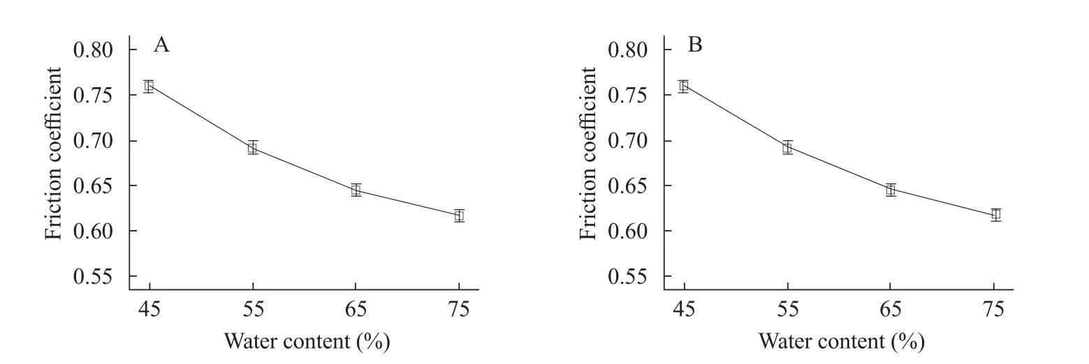
Fig. 3 Single factor analysis on sliding friction to A (friction coefficient by water content) and B (friction coefficient by positive pressure)
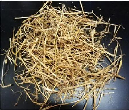
Fig. 2 Test sample
Analysis and Design
Force analysis
During the working process of the feeding device,the material had a trend of axial downward and radial circular motion under the joint action of blade thrust,material interaction force, self-gravity and hopper resistance, and the spiral surface unfolded according to the spiral angleθ. ParticleMwith a radiusRequalled to the spiral axis was taken as the research object, and the force was analyzed, as shown in Fig. 4 (Yu, 2015).
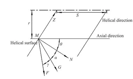
Fig. 4 Force analysis of straw
In Fig. 4,Fwas the thrust of the spiral blade to the material,Gwas gravity,Nwas the interaction force between the materials andZwas the resistance. The sum of angleαand angleγwas the friction angle andSwas the pitch.
The resistance to the material included the external frictional resistance of the material and the spiral and internal frictional resistance generated by the relative motion adjunct materials. When the screw shaft rotated at rotation speedn, materialMmoved in the axial direction and the circumferential direction under the combined forces ofF,G,NandZand the respective component forces are shown in formula (1).

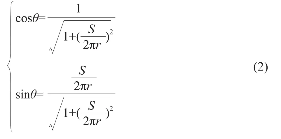
Where,FzandFTwere the resultant forces of materialMin the axial direction and the radial direction, respectively, andμwas the friction coefficient andμ= tan (α+γ). The triangular transformation was performed on formula (1), and the relationship among the spiral angleθ, the blade radiusrand the pitchSwas obtained as shown in formula (2).
The pitchSand the helix angle had a relationship,as shown in formula (3).

From the analysis of formulas (1), (2) and (3), the radial force and axial force were the functions of the blade radius, the friction angle and the helix lift angle with the screw shaft rotated at rotation speed unchanged. Then tests were designed based on this result.
Kinematic analysis
During the transmission process, the material would move forward due to the compound effect of the axial force and the radial force which produced the speed in the axial directionvzand the speed in the radial directionvt, respectively. The results of the kinematics analysis of the straw material is shown in Fig. 5 (Maet al., 2010).
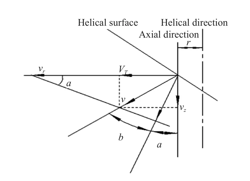
Fig. 5 Kinematics analysis of straw
Based on the vector triangle method, the motion state of the straw material and the formula (4) could be obtained. In the formula,vwas the absolute velocity of materialM(m · s-1),vrwas the circular motion velocity (m · s-1),vTwas the radial velocity of the straw raw material (m · s-1),vzwas the axial velocity of the straw raw material (m · s-1),rwas the distance from the straw material to the axis (m),ωwas the angular velocity of the spiral blade (rad · s-1) andnwas the rotational speed of the spiral blade (r · s-1). Combined formulas (2), (3) and (4) to obtain formula (5).

Formula (5) showed when the spiral blade sizes were constant, the axial velocity and the radial velocity were the functions of the rotational speed of the helical shaft and the angle of the spiral. Therefore, the rotational speed of the helical shaft should be designed as a test factor.
Structural design of key components
Long straw was easy to wind by the spiral shaft during the transmission process, which increased the viscous force of straw and led to clog. To avoid straw entanglement, the straw lengthLand the helical shaft diameterdshould satisfy the relationship as shown in formula (6).

The maximum length of wheat straw processed by the cutting machine was 147 mm,d≥46.8 mm according to the calculation. At the same time, for different pretreatment materials, 60 mm was selected as the diameter of the spiral shaft. The amount of spiral conveyance was generally related to the spiral diameter, the screw shaft speed, the pitch and the material characteristics and could be calculated by formula (7).

Dwas the initial helix diameter (mm),dwas the end helix axis diameter (mm) andnwas the spiral shaft speed (r · min-1),twas the pitch (mm),ρwas the loose density of material (kg · m-3),φwas the filling factor andCwas the conveyor inclination coefficient. The continuous and stable feeding of the device required the input and output to be equal. Therefore, the mass of the straw entering from the opening of the spiral endDper unit time should be equal to the mass of the straw output from the opening of the spiral endd. The compression ratio of the straw in the cone spiral was measured three times and the diameter of the spiral was designed according to formula (8).

In this formula, the inclination coefficientCwas 0.64, the filling coefficientφwas 0.35, the bulk densityρof wheat straw was 110 kg · m-3, the reference conveying machine design manualKwas 0.04 and the conveying amountQwas the productivity of the machine at 1 000 kg · h-1. The maximum diameter of the spiral was calculated to beD1>318 mm, and the minimum diameter wasd=106 mm. Considering the feasibility of processing,D1=350 mm andd=110 mm were used for the processing test.
The inclination of the spiral should be designed,according to the feeding structure of the fibre feeding machine. The feeding operation is shown in Fig. 6(Xue, 2014). The design of the inclination angle should make the direction of the feeding force coincide with the normal direction of the main shaft, so as to increase the winding efficiency of the main shaft. According to the test, the angle between the normal direction of the main shaft and the vertical direction was 30°.
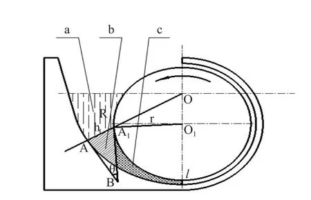
Fig. 6 Feeding throat of straw fiber extruder
Parameter Optimization Test
Test materials and instruments
Test materials: Jimai 22 wheat straw was harvested in 2018. Straw was subjected to chopping and the characteristics of the straw samples were measured and reported in Table 1. The initial water content was 13.5%viareference to the GB/T5262-2008 standard.Straw was placed in an oven and dried at temperature of (105±2)℃ for 24 h to ensure it was dry and sealed.The added amount of water was calculated, according to the moisture content of the test design, then,water and the samples were evenly mixed. The oven was sealed for 24 h as the standby condition (Chenet al., 2013).

Table 1 Test sample physical features (mm)
Test equipments: self-made spiral forced feeding device, as shown in Fig. 7; WGL-45B electric blast drying oven, Tianjin Taisite Instrument Co., Ltd.,with a temperature control range of 1℃-300℃;ATV312HU75N4 inverter, Schneider Electric Limited Company, with a frequency conversion range of 0-50 Hz; non-contact tachometer, Youlide Electronics Co.,Ltd., with a range of 0-9 999 r · min-1; electronic scale,Hualitai Electronic Weighing Apparatus Co., Ltd.,with a range of 0-300 kg; stopwatch, etc.

Fig. 7 Screw feeding test device
Test design
Using the L16(45) orthogonal test method, the pre-treated wheat straw was used as the test object, the spiral rising angle, the water content and the screw shaft speed were used as test factors; the feed efficiency was used as the test index. The level of each factor was determined based on the reference data and the pretest results. The horizontal coding of each factor is shown in Table 2.Each group of experiments was repeated 10 times and the average value was taken as the test result for each group.

Table 2 Experimental values and coded level of factors (mm)
Test results and analysis
The test results are shown in Table 3.
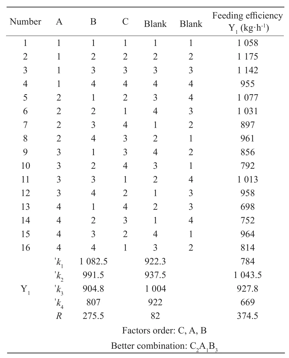
Table 3 Test results and range analysis
Using the range analysis method to analyze the level of each factor of the feeding efficiency, the best combination was found to be C2A1B3, with a spiral angle of 40°, the screw shaft speed of 200 r · min-1and the water content of 65%. From the range of theRvalue, it could be concluded that the order of in fl uence on the feed efficiency was the water content, the helix angle and the screw shaft speed. The analysis of variance results is shown in Table 4. The water content and the helix angle had a signi ficant effect on the feed efficiency (p<0.01) and the screw shaft speed had a signi ficant effect on the feed efficiency (p<0.05).
Fig. 8A showed the effect of the helix angle on the feed efficiency, when the screw shaft was at speed of 200 r · min-1and the straw moisture content was 65%.The helix angle was positively related to the feed efficiency, because when the helix angle increased, the axial force and the transmission speed also increased,thereby improving the feeding efficiency.
Fig. 8B showed the effect of the screw shaft speed on the feed efficiency, when the helix angle was 40°and the straw moisture content was 65%. The feeding efficiency first increased and then decreased with the increase of the screw shaft speed. When the screw shaft speed was 200 r · min-1, the feeding rate reached the maximum. When the screw shaft speed increased,the centrifugal force increased, the pressure between the straw and the hopper produced the increase of resistance and the axial force of the straw was gradually reduced. When the axial force was less than 0, the feeding efficiency was lowered.
Fig. 8C showed the effect of the straw moisture content on the feed efficiency, when the helix angle was 40° and the screw shaft speed was 200 r · min-1. The feed efficiency increased with the increase of the water content and then decreased. When the water content reached 65%, the feed efficiency reached the theoretical optimal result of 1 127.1 kg · h-1, because the change of the water content would change the force between the materials and the frictions of the contact surface characteristics (Yuan and Zhou, 2000; Chenet al.,2015; Miao, 2015; Chenet al., 2018; Jianget al., 2013).

Table 4 Variances analysis

Fig. 8 Single factor analysis on feeding efficiency to A (feeding efficiency by spiral angle), B (feeding efficiency by rotating speed of screw) and C (feeding efficiency by water content)
Device performance veri fication test
The test of the conveying capacity and the feeding uniformity of the verification device was carried out under the conditions of a spiral angle of 40°, a screw shaft speed of 200 r · min-1and a straw moisture content of 65%. The feeding efficiency was the average of the feeding amount of 10 unit times (1 min). The larger the mean value was, the higher the feeding efficiency was. The uniformity of the feed was re fl ected by the numerical value of the coefficient of variation. The degree of the dispersion of the variable reflected the stability and continuity of the feed. The smaller the coefficient of variation was, the more stable the device was.The results of the statistical analysis of the test showed that feeding efficiency of inclined wheat straw raw material feeding device was 1 040.8 kg · h-1with the coefficient of variation of 0.09 and standard deviation of 93.9. The conveying capacity and the feeding uniformity. Conveying capacity and the feeding uniformity of the optimal working parameter combination met the design requirements of the fibre preparation machine.
Conclusions
The primary and the secondary orders of the parameters that affected the efficiency of the forced feeding device of wheat straw were the water content,the helix angle and the screw shaft speed.
When the optimal combination of parameters was used as the pretreatment, the water content of wheat straw was 65%, the helix angle was 40° and the screw shaft speed was 200 r · min-1. The feeding efficiency of inclined wheat straw raw material feeding device was 1 040.8 kg · h-1and the coefficient of variation was 0.09 for stable operation. The tilting variable-diameter spiral feeding device designed based on the friction characteristics of wheat straw after pretreatment met the design requirements.
杂志排行
Journal of Northeast Agricultural University(English Edition)的其它文章
- Regeneration Function Analysis of GmESR1 in Transgenic Soybean
- Effect of Salt Stress on Nitrogen Assimilation of Functional Leaves and Root System of Rice in Cold Region
- Effects of Straw Returning with Different Tillage Patterns on Corn Yield and Nitrogen Utilization
- Effects of Rare Earth Lanthanum and Cerium on Antioxidant Enzyme Activities in Soybean Leaves
- Regulating Effect of Exogenous Silicon on Soil Fertility in Paddy Fields
- Uptake of B, Co and Ni by Plants from Oil Contaminated Soil Capped with Peat
