4D Conflict-Free Trajectory Planning for Fixed-Wing UAV
2020-06-01,,2*,,
,,2*,,
1.School of Aeronautics and Astronautics,Sichuan University,Chengdu 610065,P.R.China;2.Key Laboratory of Air Traffic Control Automation System,Sichuan University,Chengdu 610065,P.R.China;3.State Key Laboratory of Fundamental Science on Synthetic Vision,Sichuan University,Chengdu 610065,P.R.China
Abstract:Four-dimensional trajectory based operation(4D-TBO)is believed to enhance the planning and execution of efficient flights,reduce potential conflicts and resolve upcoming tremendous flight demand.Most of the 4D trajectory planning related studies have focused on manned aircraft instead of unmanned aerial vehicles(UAVs).This paper focuses on planning conflict-free 4D trajectories for fixed-wing UAVs before the departure or during the flight planning.A 4D trajectory generation technique based on Tau theory is developed,which can incorporate the time constraints over the waypoint sequence in the flight plan.Then the 4D trajectory is optimized by the particle swarm optimization(PSO)algorithm.Further simulations are performed to demonstrate the effectiveness of the proposed method,which would offer a good chance for integrating UAV into civil airspace in the future.
Key words:4D trajectory;trajectory planning;trajectory-based operation(TBO);unmanned aerial vehicle(UAV);particle swarm optimization(PSO)
0 Introduction
In the past decades,there have been increasingly rapid advances in the field of unmanned aerial vehicle(UAV)applications,including commercial,public or military area[1].Trajectory planning is a problem of determining a trajectory for the UAV from an initial point to the goal point.It is critical for UAV accomplishing its mission.However,most of the UAVs are restricted to operate in the rural area;even the military UAVs should use the so-called“file and fly”rule to access civil airspace.This is because most national aviation agencies can hardly specify the equivalent level of safety(ELOS)[2]requirements entailing for UAV regulations,which now presents significant barriers to research and development[3].In the future air traffic management(ATM)concepts,four-dimensional trajectory based operation(4D-TBO)concept is one of the fundamental initiatives to realize the ICAO Global ATM Operational Concept[4]and achieve the realization of the global ATM operational concept(GATMOC)[5]vision.4D-TBO will require the airspace vehicles to fly the time-metered trajectories which could offer a good chance for the UAVs safely fitting into the civil or national airspace[6].
Up to now,the concept of 4D-TBO has been tested on manned aircraft in many countries,and more will be undertaken in the future[7].The Single European Sky ATM Research(SESAR)and Next Generation Air Transportation System(NextGen)projects are two main objectives progressing 4D-TBO on manned aircraft now. As most UAVs operating in controlled airspace use waypoints to define their route instead of traditional airways,fixes,and routes,the approaches can be different from the manned aircraft.In the past decades,much previous research has focused on planning the path in a two-dimensional(2D)plane or three-dimensional(3D)space[8-9].The generalizability of such researches on UAV integration is problematic as these planned trajectories have no time information. The four-dimensional trajectory(4DT)is defined as a precise description of a flight path in space and time which includes the“centerline”of the path,using waypoints to represent specific steps along the path,together with appropriate buffers to describe the associated position uncertainty.
Trajectories are usually high-dimensional problems.Dimension reduction methods are used to reduce the dimension of the control parameter vector which is then used to optimize the trajectory.One of the easiest ways to design a trajectory is to use simple line-and-circle methods based on Dubins airplane paths,which ensures continuity for the trajectory but not for its derivatives.This way is often used in the autopilots to generate the trajectories.The benefits of this approach include simple,robust and computationally inexpensive.However,the discontinuity between straight lines or a straight line and a segment of a circle would lead to a step in the demanded roll angle,which is unacceptable. To solve this problem,the spline segments such as Bezier curves[10]and Basis-splines[11]have been utilized to generate smooth trajectories between waypoints[12-13]. Besides,there are many alternative methods are available for trajectory planning.Watanabe et al.[14]used the neural network to learn and evaluate the trajectories created by the artificial potential field and outputted the initial guess.Then the initial guess was optimized by differential dynamics programming(DDP),as the trajectory generated by the deep neural network(DNN)is not optimal but near-optimal.
Furthermore,UAVs are employed in high risk and harsh environments.Realistic mission scenarios may contain obstacles and/or other vehicles,requiring the vehicle to sense and avoid safety threats.There is a load of literature focusing on planning conflict-free trajectories.Lin et al.[15]proposed sampling-based path planning methods for UAV dynamic obstacle collision avoidance.
It is of interest to integrate UAVs into the civil airspace based on the TBO concept.Planning conflict-free 4D trajectories for the UAVs in different scenarios while satisfying appropriate flight constraints is critical to the integration.However,most of the conventional methods assign speed profile to the 3D trajectory and introduce a discontinuity in the curvature of the trajectory.Though the discontinuity of the planned trajectory can be alleviated by using high order polynomial curve.Those methods are not specially designed for 4D trajectory and imply a high computational burden.The bio-inspired Tau theory was first used as visual guidance and then extended to the area of control strategy[16].It can synchronously plan the time-variant position and velocity,offering the advantage of a trajectory which is C0,C1,and C2 continuous.In this paper a trajectory generation technique based on Tau guidance law quickly computed a non-optimal even infeasible initial trajectory,then the trajectory was optimized by a stochastic optimization technique called particle swarm optimization(PSO)algorithm.This proposed approach has the following advantages:(1)It can find a feasible 4D trajectory in a relatively short time,and(2)can be applicable to different operating scenarios before departure or during the flight planning.
The contribution of this paper is a proposed approach for planning a feasible conflicts-free 4D trajectory for fixed-wing UAV operating in different scenarios.In the remaining of the paper,we will formulate the problem,describe the method and present the experiment validations.
The following sections of this paper are organized as follows.Section 1 presents the mathematical model of the 4D trajectory planning for UAVs problem in the scenarios that we are considering.In the first part of Section 2,a resolution approach based on Tau theory to generate a 4D trajectory is discussed. After that,the optimization algorithm called PSO and a method to compute the value of the cost function are detailed. Numerical results from computational experiments are presented in Section 3.Finally,conclusions and perspectives are discussed in Section 4.
1 UAV Model
1.1 Problem statements
The input to this 4D cooperative trajectory planning problem is the UAV's initial flight plan,which is expediently described as a sequence of discrete virtual waypoints associated with assigned scheduled time of arrivals(STAs)from the start waypoint to the target.The time-constrained waypoints consisted in the flight plan are stated in the inertial reference frame of coordinates as

whereW iis theith waypoint vector in the UAV's flight plan;xi,yiandhiarex-,y-andh-components of theith waypoint in Cartesian space,respectively;tiis the STA,i.e.the time when the UAV is supposed to fly over theith waypoint,andnWis the number of waypoints. The East-North-Up(ENU)coordinate system with an origin at the arbitrary Earth surface and axes directed to the north,the east,and vertically upward is used in this paper.
A piece-wise trajectory consisting of(nW-1)trajectory segments for each UAV is defined in this paper. Each trajectory segment is constructed by one parametric curve using Tau guidance theory and the parameters controlling the curves are optimized using the evolutionary technique and the PSO algorithm.
1.2 UAV model and constraints
Since many large fixed-wing UAVs are based on military or general aviation aircraft,they share aspects of the design and construction of the airframe and mechanical components.For simplicity,it is common to consider a three-degree of freedom dynamic model that describes the point motion of the fixed-wing UAV over a spherical flat Earth model.It is assumed there is no sideslip and all forces lie in the plane of symmetry of fixed-wing UAV.The three-dimensional point-mass equations of motion for a generic fixed-wing UAV expressed in the bodybased reference frame are[17]

subject to

wheremis the UAV mass which assumed to be a constant in this paper;gthe gravity acceleration;̇,anḋare the true airspeed rate,the heading angle(turn angle)rate,and the flight path angle(climb angle)rate in the vehicle-carried vertical frame,respectively;Tis the engine thrust andφthe bank angle;LiftLand dragD,which depend on the flight height,the true airspeed and the angle of attack,etc.,are the components of the aerodynamic forces applied to UAV.
The three kinematic equations of the fixedwing UAV in the ground-based reference frame are stated as follows

subject to

whereandare the velocity components of the fixed-wing UAV;hmaxandhminthe maximum reachable altitude and the minimum cruise altitude assumed to be limited,respectively;vmaxandvminthe maximum and the minimum true airspeed,respectively;γmaxandγminthe maximum and the minimum flight path angle,respectively.The fixedwing UAV cannot follow a path with sharp turns or vertices.
2 Methodology
2.1 Tau guidance theory
General Tau theory[18]was presented in the 1970s and first used as visual guidance.It was adapted to generate a 4D trajectory between two arbitrary waypoints for the UAV in this paper.The Tau guidance theory shows that,in principle,controlling the closure of any action-gap only requires Tau information. The information about,e.g.,the size and speed of closure of the action-gap is not needed[19].
In general Tau theory[20],the Tau of an actiongapμ(t)is defined as
whereis the first-order derivative of actiongap,μminthe minimum value of action-gap,andτminthe minimum value of Tau.The action-gapμ(t)is defined as the separation between the current state and the goal state to be achieved.
The Tau coupling theory ensures that the different action-gaps,of the guidance movement and the guided movement,reach closure simultaneously if their Tau variables maintain a non-zero constant ratio.The Tau-coupling equation can be expressed as
where the constant ratiokis called the coupling coefficient.X0andare the initial value of the coupled action-gapX(t),which is also called the guided movement,and its first derivative,respectively.The action-gap of the coupled movement,its first derivativeand second derivativecan be obtained by solving Eq.(7).

whereμ0is the initial value of the action-gapμ(t).
The Tau theories have been continuously developed and most of the exist Tau guidance theories are particularly applicable when braking at the end of a movement[21].The initial state and target state of the realistic movement could be dynamic or still.However,these general Tau theories could not be used when the start velocity and the target velocity of the guided movement are non-zero.Inspired by the intrinsic Tau gravity guidance,the modification of the Tau theory in this paper is defined as

whereandμ0are the initial acceleration,the initial velocity and the initial value of the guidance action-gap,respectively. According to the coupled movementcan be set to positive,negative or zero.
Suppose the guided movement starts from pointx0at the STA oft0and ends at pointx1at the STA oft1,and the initial velocity and the target velocity areand,respectively.The action-gap and its Tau function of the guided movement are expressed as

According to Eq.(8),the velocity function of the guided action-gap is defined as

whereCis the coefficient of the guided movement.The movement function and acceleration function are derived from Eq.(12)as

wheret0≤t≤t1.Substituting Eq.(9)into Eq.(13)yields

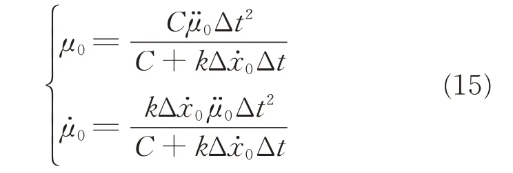
The parameters of the guided movement,Δt,andC,and the parameters of the guidance movement,and,connect the two actions and ensure their action-gaps reach closure simultaneously.
The value ofkdetermines the kinematic aspects of the movement(Fig.1)and subjects to(0,0.5).The higher the value ofkis,the more delayed the peak velocity is,the shorter the deceleration phase is,and the higher the deceleration at the end is.
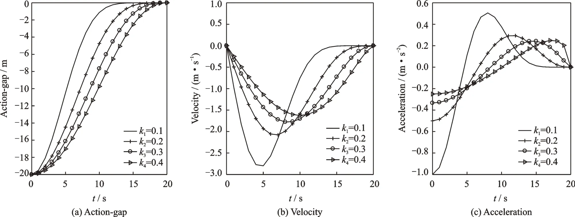
Fig.1 Kinematic curves of the guided movement
To ensure the closure of the action-gap at the right timet1,the guidance action-gapμ(t)should be positive in the time range[t0,t1),andμ(t1)=0;otherwise the gap will close in advance or the Tau theory will be invalid.To ensure the guidance theory valid,the parameter values should obey the requirements as follows
According to Eq.(17),μ0andhave the same singularity when(1)andIn this case,letand Eq.(11)can be rewritten as

whereand.It means that the closure of action-gap is guided by a uniform rectilinear motion.
Suppose one trajectory segment,Γ i,of the UAV mission from the arbitrary waypointW i(xi yi hi ti) towards the next waypointW i+1(xi+1yi+1hi+1ti+1)over a period of Δt.The Tau-coupling equations of the UAV movement in Cartesian coordinate system are depicted as

wherekx,kyandkhare the Tau-coupling coefficients inx-,y-andh-axis,respectively.The trajectory segmentΓ iinx-axis can be determined as


Suppose the flight plan of one UAV includesnWwaypoints,then the solution vector for generating the complete 4D trajectory is denoted as

The 4D trajectory planning problem can be formulated as an optimization problem whose solution is the parameter vector controlling the whole 4D trajectory as Eq.(22).
2.2 PSO and cost function
The PSO algorithm is inspired by the flock of birds as an intelligent swarm,which was first proposed by Eberhart and Kennedy in 1995[22].It is simpler than other Evolutionary techniques as it requires only the specification of the problem and a few parameters to solve it.
In PSO,each particle representing a potential solution to a defined problem can communicate with others and share their information.When searching for a solution,most of the particles will converge on the best possible solution for the defined problem.
To help to ensure convergence,a constriction factor[23]is introduced in the particles'velocity update and calculated as

wherec1+c2≥4.c1andc2are the cognitive and the social acceleration coefficients,respectively.Particles in the swarm(ofsparticles)are searched by the following formulas

where 1≤j≤s,V jis thejth particle's velocity vector,P jthejth particle's current position vector,P bjthe best position vector found by thejth particle so far,the best position vector found by the swarm so far,andithe iteration count.r1andr2are random numbers drawn from a uniform distribution.
To guarantee the finite particles are evenly distributed over the entire solution space,the chaotic mapping is used to initiate the particles.At the same time,the solution vector is normalized.
Most of the constraint-handling methods are based on the concept of(exterior)cost functions in evolutionary computation[24].The weakness of the traditional cost functions is in the number and value of parameters[25].If the solution vector is inside the feasible region,the trajectory generated by the guidance law is feasible;if the solution vector is outside the feasible region,the trajectory generated by the guidance law is infeasible or invalid.According to this situation,the mechanism applied to construction cost functions is based on the following principles.
(1)For all feasible solution vectors,the solution vectors with lower costs are better than the higher ones.
(2)For all infeasible solution vectors,the solution vectors with lower violations are better than the higher ones.
(3)Among all solution vectors,the feasible ones are better than the infeasible ones and the invalid solution vectors are the worst of all.
One of the most used utility functions to evaluate the search parameter vector of the UAV is to minimize the length of the planned 4D trajectory.The total cost of a potential solution vector for 4DTP is
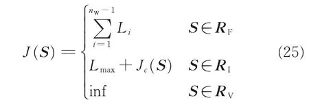
whereL iis the trajectory length of trajectory segmentΓ i,Jcthe violation of the infeasible solution vector,Lmaxthe longest trajectory length of all feasible solution vectors in the searching past,RFthe feasible region,RIthe infeasible region,andRVthe invalid region.The feasible region,infeasible region and the invalid region construct the whole search space.If there is no feasible solution vector so far,Lmaxis set zero;if the solution vector is in the invalid region,the cost function is set infinite.The fitness of an infeasible solution not only depends on the amount of constraint violation but also on the population of solutions at hand.
The solution vector is obtained by solving the following problem

The violation costJcconsists of several components including the height cost,true airspeed cost,and climb angle costs.Take the violation of flight height as an example and the height cost can be described as

3 Case Study
3.1 Simulation setup
To demonstrate the 4D trajectory planning approach performance,several simulation scenarios were examined.The model was implemented using MATLAB and Visual Studio on a Windows 7 Ultimate platform(64-bit)with a 3.4 GHz Intel Core processor and 8.0 GB RAM.
The parameter values of the optimization approach were empirically selected based on suggestions in Ref.[25]to provide good performance.The time interval was set as 1 s.
3.2 Results and analysis
3.2.1 Single UAV with stationary obstacles
In this case,a virtual simulation environment was created with several stationary obstacles and NFZs in appropriate locations.Possible obstacles in airspace are large trees,mountains,and skyscrapers,of which the trajectory should keep the clearance.The planned 4D trajectory for UAV should avoid obstacles and not cross the no-fly zones(NFZs).In this paper,we use part of a sphere to model the obstacle and the mathematical formulations are as follows

wherenFis the number of obstacles.andare the components of obstacle's position.The radiusrjconsiders the obstacle's size as well as measurement,estimation and tracking errors.The cylinder is used to model the NFZs as follows

wherenOis the number of NFZs;andare the components of NFZ's position.The radiusR jconsiders the NFZ's size as well as measurement,estimation and tracking errors.
The violation costJcconsists of the violation of NFZs and obstacles for the potential solution vector,and is calculated as follows

The result of the 4D trajectory planning approach,when the swarm size and the maximum number of iterations are set to 25 and 1 000,respectively,is obtained through the simulation.Fig.2 provides the convergence rates of fitness.
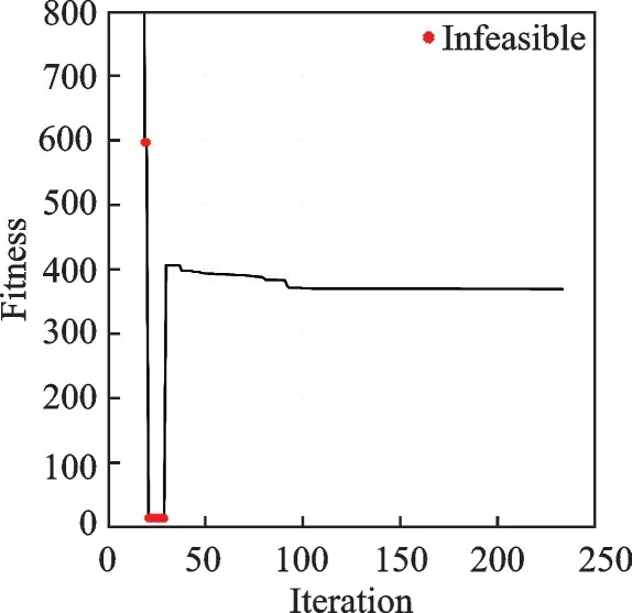
Fig.2 Fitness profile in case 3.2..1
Starting at infinity,the fitness value dramatically falls in the early stage before it finds the first feasible solution vector,and then it begins to decrease slightly until the optimization algorithm reaches the stopping criteria and converges to 368.67.
Fig.3 shows the planned 4D trajectory for UAV in space.Fig.3(a)shows an overview of the planned trajectory in 3D space without the time dimensional information.As it is shown in Fig.3,the planned 4D trajectory avoids the obstacles and NFZ successfully.It can be seen more clearly in Fig.3(b).Figs.3(c)and(d)illustrate the time varied position in the 2D plane and flight height,respectively.It can be seen from Fig.3(d)that the vertical flight profile keeps in the boundary of the nominal flight height,i.e.300 m below or up 5 km.
Figs.4 and 5 provide some more details of the planned trajectory.
The flight path angle and the true airspeed of the planned 4D trajectory vary in their boundaries,i.e.subject to the constraints:and
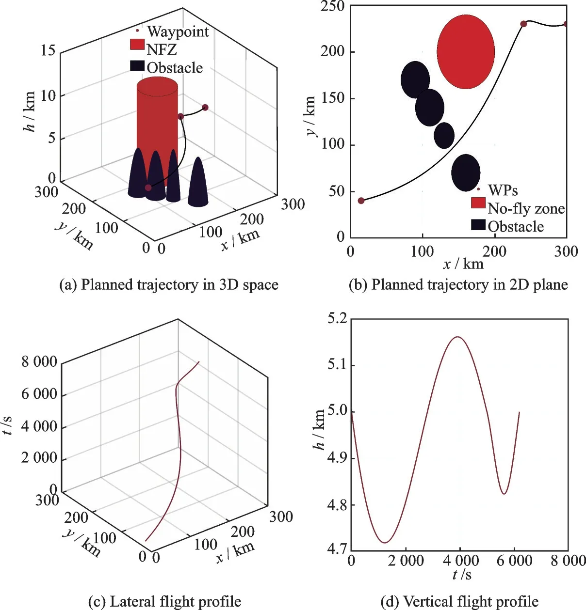
Fig.3 Planned 4D trajectory for the single UAV in case 3.2.1

Fig.4 Kinematic curves of the UAV in case 3.2.1
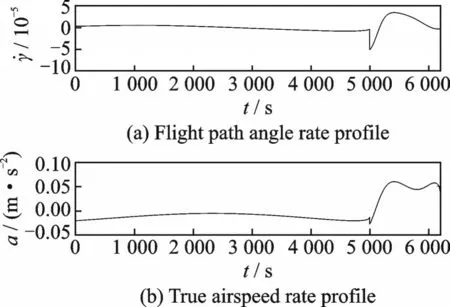
Fig.5 Rate curves of the kinematic variables of the UAV in case 3.2.1
As can be seen from Fig.5,the values of flight path angle rate and acceleration subject to the following constraints:and
Further to test the performance of PSO,the results of the approach calculated from 100 runs for each given swarm size are shown in Fig.6 and Table 1(when the number of iterations is no more than 1 000).
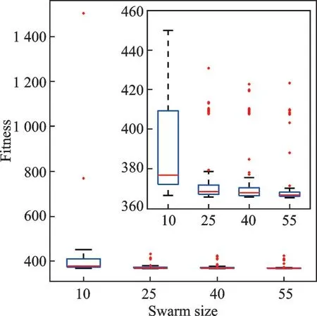
Fig.6 Box plot of the fitness value in case 3.2.1

Table 1 Statistical results of 100 runs
In Table 1,“nSolu”column presents the number of feasible solution vectors in 100 runs,“Fitness”column presents the mean value and the standard error of fitness of all feasible solution vectors,“Time”and“nEval”columns present the mean time and number of function evaluations for fixed swarm size.What stand out in Table 1 is that the number of feasible solution vectors is less than 100 when the swarm size is set to 15.It means the approach cannot find a feasible solution vector surely when the iteration is equal and less than 15.The mean value and standard error of the fitness decrease with the swarm size generally,while the mean time and the mean number of function evaluations increase with the swarm size.
Then,a deeper analysis of the value of fitness is carried out.In Fig.6 each box visually represents the fitness data of cars for a given swarm size when the number of iterations is no more than 1 000.
On each box in Fig.6,the central mark is the median,the edges of each box are the 25th and 75th percentiles,the whiskers extend to the extreme data points not considering outliers,and the outliers are plotted individually using the“+”symbol.As we can see that the median and maximum values of the group decrease with the swarm size.The median,maximum value,minimum value,and outliers of the first group are much higher than that of the last three groups.
3.2.2 Single UAV with cooperative manned aircraft
The last simulation focuses on the static obstacles handling while moving obstacles are more often found in a real environment. In this case,the manned aircraft(MAC)in this simulation is introduced to cruise at the same true airspeed in the same airspace with the UAV.Also,the UAV is supposed to fly on the same flight level and the planned 4D trajectory of UAV should keep clearance of the MAC all the time.Through the simulation,the violation cost should include the violation of MAC for the potential solution vector.
The result is obtained through the simulation when the swarm size and the maximum number of iterations are set to 25 and 1 000,respectively.Fig.7 presents the change of fitness with the number of iterations.

Fig.7 Fitness profile in case 3.2.2
The shape of the fitness profile in Fig.7 is the same as Fig.2 in general.The value of fitness drops dramatically to zero and then rises sharply to a definite value,which means the optimization algorithm finds the first feasible solution vector.The algorithm will keep on finding smaller fitness values in the rest of iterations and converges to 241.67.Fig.8 shows the planned trajectory more intuitively.
As can been seen in Fig.8(a),the planned trajectory of UAV do not cross the trajectory of MAC inx-,y-axes and time dimension.The lateral distance between UAV and MAC keeps more than the minimum lateral separation(set to be 4 km in this paper)as shown in Fig.8(b).And in Fig.8(c),the flight height of UAV keeps within the limits of 300 m up and down the nominal flight level.
Figs.9 and 10 present more flight control details of the UAV's planned trajectory.
Fig.9 shows the state of the UAV,including the flight path angle and the true airspeed.It can be seen that the state keeps in each boundary,i.e.and
Fig.10 presents the rate of state,including the flight path angle rate and the acceleration. The values of the state of UAV subject to:and

Fig.9 Kinematic curves of the UAV in case 3.2.2

Fig.10 Rate curves of kinematic variables of the UAV in case 3.2.2
To assess the influence of the PSO algorithm,simple statistical analysis is applied to the results calculated from 100 tests for each assigned swarm size.Table 2 compares the result difference between different swarm sizes.

Table 2 Statistical results of 100 runs
It can be seen from the data in Table 2 that the mean value and standard error of the fitness decrease with the swarm size generally,while the mean time and the mean number of function evaluations increase with the swarm size. When the swarm size equals 10,the approach only succeeds to find the feasible solution vectors 95 times out of 100.And when the swarm size is bigger,the approach can find a feasible solution vector 100 times out of 100.At the same time,the mean time to finish the optimization is 397.36 s when the swarm size equals 55,far more than that of others. It means that the more particles the harder to converge for PSO.
Fig.11 shows a deeper insight and each box of the figure depicted the statistics of the fitness for a given number of iterations.

Fig.11 Box plot of the fitness value in case 3.2.2
The median value of the group decreases with the swarm size generally.It is apparent that the maximum value,minimum value,and outliers of the first group are larger than the other three,even the outliers of the first group are bigger than others for several orders of magnitude.A possible explanation for these results may be the lack of adequate function evaluation.No significant differences between the lateral three groups are observed.
3.2.3 Multi UAVs with manned aircraft
A more complicated dynamic scenario is constructed in this case,in which multi UAVs are assigned to follow its flight plan in the 4D trajectory planning airspace.Figs.12―15 and Table 3 show a similar,but more pronounced scenario.
In this simulation,the swarm size equals 25 and the number of iterations is set to be 1 000.Fig.12 depicts the convergence of fitness.

Fig.12 Fitness profile in case 3.2.3
The fitness value also falls firstly,then increases to a definite value and converges to 876.33 at last.What is interesting in Fig.12 is that the number of iterations approximates 200 when the growth inflection emerges.The number of iterations,when the feasible solution vector is found,is far more than that in the last two cases.A possible explanation for this might be that this case is far more complicate than the last two and the optimization algorithm needs more iterations to find a feasible solution vector.
Similarly,Fig.13 presents the planned trajectories of the UAVs and the lateral separation profiles between UAVs and MAC.The lateral safe distance between UAVs is set to 4 km,and vertical safe distance is 300 m lower or higher than the nominal flight height.

Fig.13 Planned 4D trajectories for the UAVs in case 3.2.3
As can be seen in Fig.13(a),there is no intersection point between the planned trajectories of UAVs and the assigned trajectory of MAC in thexaxis,y-axis and time dimensions.The lateral distance within UAVs or between UAV and MAC keeps more than the minimum lateral separation(2 km in this case)as shown in Fig.13(b).And in Fig.13(c),the flight height profiles of UAV vary within the limits of 300 m up and down the nominal flight level.
The state of the planned trajectories of the UAVs is presented in Figs.14 and 15.
It can be seen that the state keeps in each boundary,and
Also,the rate keeps in each boundary,i.e.and
In order to verify the stability of the approach,repeated tests are implemented at last.

Fig.14 Kinematic curves of the UAV in case 3.2.3
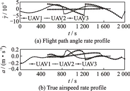
Fig.15 Rate curves of kinematic variables of the UAV in case 3.2.3

Table 3 Statistical results of 100 runs(MaxIter=1 000)
In this case,the number of feasible solution vectors is less than 100 no matter how large the swarm size is.The number of feasible solution vectors is rather disappointing when the swarm size is set to 10.Though the mean value and the standard error of the fitness decrease with the swarm size generally,the mean time and the mean number of function evaluations increase with the swarm size.Surprisingly,the mean time consumed increases sharply when the swarm size is set to 55.
In Fig.16,the statistics of fitness calculated from 100 runs for each given number of iterations are presented.Fig.16 shows a clear trend of decreasing the median value,the maximum value,minimum value and outliers of the groups with the swarm size.The indicators of the first group are larger than the other three.No significant differences between the lateral three groups are observed.

Fig.16 Statistics of fitness from 100 runs
4 Conclusions
This study proposed a novel 4D trajectory planning approach for fixed-wing UAV flight before departure or during the flight planning in the future integrated airspace,which is one of the great challenges for the ICAO's Global TBO concept.The 4D trajectory planning approach for UAVs collectively performs well in the test cases.The illustration of the proposed approach proves its ability to plan the 4D conflict-free trajectory efficiently for single UAV and apply to the scenarios in which multi UAVs can fly cooperatively with moving manned aircraft,which is highly significant in the future application.This present study lays the ground work for future research on UAV integration into the civil airspace.
Despite these promising results,some questions still remain.The 4D trajectory planning approach only considers the fixed STAs instead of the time window for each of the waypoint in the flight plan.Also,there is abundant room for further progress in modeling the disturbance,such as the wind disturbance.Additionally,the UAV must be able to overcome environmental uncertainties such as modeling errors,external disturbances,and an incomplete situational awareness.Further studies,which take these variables into account,will need to be undertaken.
杂志排行
Transactions of Nanjing University of Aeronautics and Astronautics的其它文章
- Key Technology in Multi-UAV Conflict Detection and Resolution Strategy
- Empirical Exploration of Air Traffic Control Behaviour at Terminal Maneuvering Area:From an Air Traffic Flow Aspect
- A New Meta-Heuristic Approach for Aircraft Landing Problem
- Air Route Network Generation Based on Traffic Assignment
- Prediction of Departure Aircraft Taxi Time Based on Deep Learning
- Airway Network Characteristics Based on Complex Network Model
