A 16-channel high-voltage reconfigurable and flexible-controlled implantable wireless closed-loop system for SCI repair①
2020-04-13YanHanbing闫寒冰ZhangXuLiuMingYuanFangWangSikaiChenHongda
Yan Hanbing (闫寒冰),Zhang Xu,Liu Ming,Yuan Fang,Wang Sikai,Chen Hongda
(*State Key Laboratory on Integrated Optoelectronics,Institute of Semiconductors,Chinese Academy of Sciences,Beijing 100083,P.R.China)(**University of Chinese Academy of Sciences,Beijing 100049,P.R.China)
Abstract
Key words:spinal cord injury (SCI) repair,implantable medical device,multi-electrode array,reconfigurable system,functional electrical stimulation
0 Introduction
In recent years,the number of disabled patients with spinal cord injury (SCI) caused by disease or trauma has increased significantly.SCI often leads to neurological visceral dysfunction below the injury plane,such as double barriers to bladder storage and urination[1].Frequent reflex urinary incontinence and high bladder pressure as well as their complications are extremely harmful to the patient’s life expectancy.With multidisciplinary integration,there has been a growing interest in closed-loop implantable devices for SCI repair.They have low risk of infection,convenient and patient friendly.However,certain issues still limit the commercialization of implantable devices.
Various kinds of chronic physiological responses may cause poor connection between electrodes and tissue,and this situation is not conducive to long-term implantation.Improving electrode density is a viable way to solve this issue[2].However,the use of multiple electrodes in small anatomical spaces is challenging[2,3].It requires implantable device to flexibly coordinate these electrodes for sensing or stimulating.
The implantable stimulator is confronted with large electrode-tissues contact impedance (Zetc),so high driving voltage becomes necessary to deliver the requisite charge to the target tissue in triggering the desired level of neural response[4-7].Due to the generation and growth of scar tissue in the body,Zetc will continue to increase after the electrode is implanted[5,7],which means that practical stimulators must support high headroom voltages.
Artifacts are inevitably recorded together with normal neuronal electrical activity,which would be several times larger than the target neuron potentials in amplitude[8,9].Besides,artifacts will also saturate the recording amplifier[10].This puts requirements on the recording system to capture signals effectively and clearly.
Several research institutions have used commercial off-the-shelf (COTS) electronics or application specific integrated circuits (ASIC) to realize a closed-loop neural interface[9,11-15].However,none of the systems cover a wide range driving voltage,multiple electrodes and flexible reconfiguration together.In this work,a closed-loop system for implantable SCI restoration is presented to solve the aforementioned issues.Two custom switches are designed to address the requirement of configuring 32/16 electrodes online in response to larger integration and better signal sensing.All electronics are driving at high voltage to prevent saturation and to eliminate DC drift.Artifacts can be appropriately eliminated by controlling the on-time of the switch.The whole system is implemented on printed circuit boards (PCBs) using 2 switches and COTS electronics.
1 System design
1.1 System overview
The overall structure of the closed-loop system designed is shown in Fig.1.The in vitro devices include the data acquisition device (DAQ) (NI USB-4432),a wireless power transmission and a personal computer (PC).The PC terminal receives the recording signals from the DAQ and transmits control signals to the micro control unit (MCU).

Fig.1 Overall system design
The in vivo implanted part consists of electrodes,an amplifier module,a stimulation module,a control part and wireless power interaction.There are 32 electrodes combined with the SAS1T16X2 switch are used for stimulation.The SAS1T16X2 is a 32-channel single-pole,double-throw switch that supports up to 2 electrodes simultaneously and provides tissue with bipolar current pulses.For signal recording,these 16 electrodes form 16 pathways with SAS3T16.The SAS3T16 is a 16-channel single-pole,three-throw switch,which is able to simultaneously acquire signals from 3 electrodes and apply them as differential inputs and reference inputs respectively to the amplifiers.Both the amplifier and the stimulator are high voltage driving.
1.2 Electrode
Flexible PCB of polyimide substrate is used in the implantable electrodes.The contact points adopt the sinking gold method to reduce the contact resistance and improve the electrochemical stability.Polyimide has good biocompatibility and has been shown to be suitable for use in implantable devices through in vitro cytotoxicity assays[16].As shown in Fig.2,the fabricated electrodes are divided into 4 groups,each group has 8 electrode points and is available in 2 sizes.The stimulation electrodes are multiplexed with the amplified electrodes to save volume.Depending on the situation,the appropriate point can be selected for the stimulation/recording,which greatly increases the flexibility.

Fig.2 Flexible implantable electrodes
1.3 Neural amplifier
The neural signal amplifier includes a radio frequency (RF) filter,a preamplifier,a low pass filter,a high pass filter,and a variable gain amplifier,as shown in Fig.3.Due to the large RF interference in the environment,an RF filter is designed to filter out the high frequency noise and maintain the stability of the amplifier.The high voltage,single-supply and low-noise instrumentation amplifier (INA188,Texas Instruments) is used in the preamplifier,in which the gain is determined by the R7 (51 dB by 1 kΩ).A feedback loop is designed to reduce common mode interference.Then the low-pass and high-pass filter with a total gain of 10 dB and a filtering range of 300-3 000 Hz are designed.The variable gain amplifier uses the adjustable resistor R17(50.5-50 kΩ) and its gain is controlled in the range of 1-60 dB.As a result,the entire amplifier system is designed with an adjustable gain from 61 dB to 120 dB and a flat response frequency from 300 Hz to 3 000 Hz.

Fig.3 Neural amplifier
1.4 High-voltage stimulator
The human tissue environment is complex,and the electrode-tissue interface has capacitive and resistive components.Even if the impedance is fully characterized in the laboratory,it would change after implantation.The traditional voltage stimulation mode means the current output to the action site is not constant,making it difficult to control the total charge injected into the tissue per unit of time.And the desired stimulating may cause tissue burns and the effects are often not satisfactory.Therefore,the current stimulation mode is used to control the injected and extracted charges precisely.
Fig.4 shows the designed stimulator.Symmetric bipolar pulses are generated by the DAC(TLV61046A,Texas Instruments).Then the pulse waveforms are integrated by the high-voltage amplifier (OPA2277,Texas Instruments) to increase the allowable voltage amplitude to the supply voltage.To improve the load carrying capacity,the high input impedance of the operational amplifier is used to increase the output impedance of the stimulator.The amplitude and period of the generated pulses can be flexibly controlled by the control unit to achieve the desired stimulation effect.
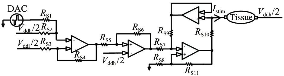
Fig.4 Neural high-voltage stimulator
1.5 Central process module
The selection of the effective pathway and the stimulator pulse are controlled by MSP430F149 (Texas Instruments).The control signals and their data format are shown in Fig.5.

Fig.5 The data format of control signals
Two switches are configured through their own serial peripheral interface (Din,SCLK,Csn).The data format of Dinis 16 bits,with the first 5 bits being flag bits,then,just as for SAS3T16,A0A1A2A3 selects 16 electrode paths,E0E1 selects the access to INP,INN or INC.For SAS1T16X2,A0A1A2A3A4 and E0 address the 32 electrodes and INP/INN respectively.Csn is the enable port,controlling whether the switch is turned on or not to reduce unnecessary power consumption when stimulation or recording are not required.
The serial peripheral interfaces of DAC also include Din,SCLK and Csn.The input shift register is 16 bits wide:the first 2 bits are reserved control bits for setting the desired operating mode (normal mode or 3 power-down modes),the remaining data bits are 12,10,or 8 data bits followed by don’t care bits.Csn enables the input shift register and write data is valid when low.
Electrical stimulation generates stimulus artifacts that last about 10 ms after electrical stimulation[3].Therefore,the influence of the stimulation artifacts on the recorded signal can be effectively eliminated by controlling the delay period between stimulation and recording.Fig.6 shows the data transfer process for a complete stimulation and recording process.Firstly,configure the path of the two switches.Then,enable the switches and DAC as needed,and configure the DAC to generate the stimulus waveform.Finally,enable the amplifier pathway for recording.

Fig.6 The data transfer process for a complete stimulation and recording process
1.6 Power management
Power is received based on an integrated wireless power receiver (BQ51013B,Texas Instruments) and transmitted based on a wireless power controller (bq500212A,Texas Instruments).Two different coils are fabricated for wireless power transmission,which are shown in the next part.A rechargeable lithium battery (301 525) with the size of 3 mm×15 mm×25 mm is adopted for power supply in vivo and provides a 3.7 V output voltage for low-power devices in implantable systems.
The low voltage is converted by a boost regulator (TLV61046A,Texas Instruments) to 28 V for driving the high-voltage part.TLV61046A has an isolating switch;when setting the operating mode to shutdown mode,the isolating switch disconnects the output from the input to minimize leakage current.In addition,the TLV61046A features output short-circuit protection,output overvoltage protection,and thermal shutdown to prevent overheating of the circuit and tissue burn.
2 Test results
2.1 Overall device
Fig.7 shows the photography of the fabricated system,where Fig.7(a) is the electrodes and the overall package,whose volume is 42 mm×35 mm×8 mm,while Fig.7(b) is the details of each part and Fig.7(c) is the micrograph and package of 2 switches.

(a) The electrodes and the overall package

Fig.7 The photography of the fabricated system
2.2 Amplifier
To verify the reconfiguration performance of the amplifier,three inputs,a 5 mV/1 kHz,a 10 mV/1 kHz sinusoidal signals and a zero signal,are provided to SAS3T16.Then these signals are recorded by controlling the on/off of these 3 channels.The gain of the amplifier is set to 50 dB.Fig.8 is the amplified signals.
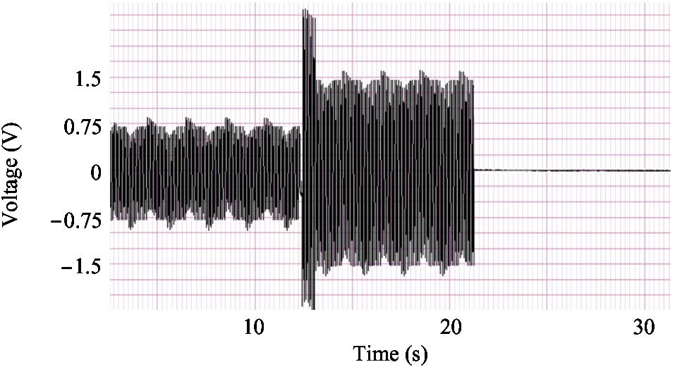
Fig.8 Amplified signals from 3 channels
2.3 Stimulation waveforms and control signals
The driving voltage is 28 V and the reference voltage is 14 V in this test.Meanwhile,a 5 kΩ load resistance is connected to the output of the stimulator to convert the output current to a voltage,where the single-phase currents of stimulator are set to 1 mA/200 μA and the converting voltages are 5 V/1.5 V.Fig.9 shows 3 different stimulation modes:waveform 1 and 2 are symmetric biphasic pulses,and the amplitude is 5 V.Waveform 3 is a charge-balanced asymmetric pulse,and the cathodic phase is 5 V and the anodic phase is 1.5 V.Waveform 2 and 3 have a discharge phase (300 μs) between cathodic phase and anodic phase to remove residual charge at the electrode-tissue interface.

Fig.9 Output waveforms of the stimulator
Fig.10 is the control signals of a complete stimulation and recording.When Csn_2 is enable,the stimulator injects charge into the tissue.In addition,it is worth noting that the delay time is set to 500 μs and 2 ms respectively in this test to effectively eliminate the influence of artifacts.
2.4 Discussion
Table 1 compares the proposed system with other similar systems published in recent years on various factors listed in the first column.The comparison shows that the system can provide wider operating voltage and more recording electrodes channels while maintaining advantages on the other factors.

Fig.10 Control signals
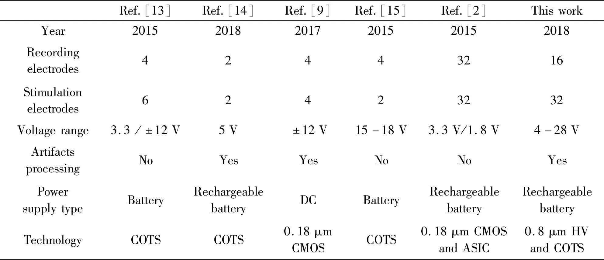
Table 1 Comparison of the implantable closed-loop system
3 Conclusion
In order to solve the difficulties encountered in the SCI repair device (low flexibility,low integration,artifacts influence),a multi-electrode reconfigurable high-driving-voltage system is designed to simplify reconfiguration on different modes.It combines monolithic switches with COTS.In the end,tests and comparison have been done to prove the proposed system is feasible and innovative.In addition,the system is highly versatile for other implantable medical devices to realize their own functions.
杂志排行

High Technology Letters的其它文章
- A bibliometric analysis of gene editing research①
- A hybrid optimization approach for the heterogeneous vehicle routing problem with multiple depots cooperative operation①
- Airport gate assignment problem with deep reinforcement learning①
- Research on transient characteristics of cavitation phenomena in pilot stage of jet pipe servo-valve①
- Optimization of yield criterion and simulation based on QP980 high strength steel①
- Model-free adaptive control of space manipulator under different gravity environment①