Study of the Surface Morphology of Gas Hydrate
2020-03-10SUNJianyeLIChengfengHAOXiluoLIUChanglingCHENQiangandWANGDaigang
SUN Jianye , LI Chengfeng , HAO Xiluo , LIU Changling , ,CHEN Qiang , and WANG Daigang
1) The Key Laboratory of Gas Hydrate, Ministry of Natural Resources, Qingdao Institute of Marine Geology,Qingdao 266071, China
2) Laboratory for Marine Mineral Resources, Pilot National Laboratory for Marine Science and Technology,Qingdao 266071, China
3) International Center for Gas Hydrate, Peking University, Beijing 100871, China
Abstract Study of the surface morphology of gas hydrate is of great importance in understanding its physical properties and occurrence. In order to investigate the surface morphology of different types (sI and sII) and occurrences (pore-filling and fracture-filling) of gas hydrate, both lab-synthesized and drilled-gas hydrate samples were measured using cryo-scanning electron microscopy (cryo-SEM). Results showed that the surface of sI hydrate was relatively smooth, and spongy nano-pores (200–400 nm)gradually occurred at the surface during continuous observation. The surface of sII hydrate was more compact, showing a tier-like structure. Hydrate occurred in quartz sand and usually filled the pores of the sediments and both hydrate and sediments were cemented with each other. SEM observation of the gas hydrates collected from the South China Sea showed that the surface morphology and contact relation with sediments varied with hydrate occurrence. For instance, hydrates dispersed in sediments mainly filled the pores of the sediments. The existence of microorganism shells, such as foraminifera, was beneficial to the formation of gas hydrate. When hydrate occurred as a massive or vein structure, it was easily distinguished from the surrounding sediments. The surface of hydrate with massive or vein structure showed two distinct characters: one was dense and smooth, the other is porous (several to tens of micrometers in diameter). The occurrence of different hydrate morphologies was probably caused by the supplement rates of methane gas.
Key words gas hydrate; surface morphology; cryo-SEM; grain contacts
1 Introduction
Natural gas hydrates (NGH) are ice-like solid compounds containing hydrocarbons, and are preserved in marine and permafrost environments. It has been estimated that global NGH contain more than 20000 trillion cubic meters of natural gas (94%–99% CH4), which is twice as much as of all other fossil fuels (Chong et al.,2016). Because of the huge reserves, NGH have been considered as one of the best clean energy supplies in the near future (Zhang et al., 2007). Understanding hydrate occurrences, spatial distribution, pore structure, and its contact relationship with sediments are essential in studying the mechanism of gas hydrate accumulation and dissociation (Liu et al., 2017), revealing its physical and chemical characteristics, reflecting reservoir-forming conditions(fluid, thermodynamic stability, etc.), and predicting the dissociation behavior of gas hydrates. In addition, studies of the surface morphology of hydrate may also be useful in examining the change of gas hydrate-bearing samples during the process of sampling, transportation, and preservation. For example, partial dissociation of hydrate samples may occur during coring operations, resulting in a change of the textural characteristics of the original hydrate-bearing samples, and affecting the accuracy in measuring their physical properties.
In recent years, studies of gas hydrate occurrence, pore structure, and its contact relationship with sediments mainly rely on X-ray computed tomography (X-CT) and nuclear magnetic resonance imaging (MRI) techniques (Rojas and Lou, 2010; Hu and Li, 2016). Although X-CT can provide visualized 3-dimensional pore structure of gas hydratebearing samples, the resolution can only reach micron level without a synchrotron radiation source. Moreover, components with similar densities (for example ice and hydrate) can hardly be distinguished in X-CT images (Jin et al., 2006; Murshed et al., 2008). Similarly, the resolution of MRI images is also unsatisfactory, and the imaging is susceptible to the hydrogen-containing substances in sediments (Moudrakovski et al., 2008; Meng et al., 2015).Due to its high resolution and large depth of focus, scanning electron microscopy (SEM) has been used for imaging gas hydrates. Using this technique, several studies have successfully observed hydrate surface morphology and the contact relationships between hydrate crystals(Stern et al., 1996; Klapp et al., 2010a). Imaging with SEM not only provides information for the study of natural hydrate reservoirs and physical properties, but also has important significance for laboratory simulation. For example, if synthetic and naturally formed gas hydrates-bearing sediment samples show similar structure and phase distributions, it would be more reasonable in using the physical properties of synthetic samples to emulate those from nature.
Investigation of gas hydrate surface morphology using cryo-SEM techniques was first conducted by Kuhs, Staykova, Klapproth and coworkers (Kuhs et al., 2000; Staykova et al., 2002, 2003; Klapproth et al., 2003). They successfully imaged and identified the grain structures of CH4, CH4-N2, CO2, and Ar hydrates generated by ice (Ih)and relevant gases or liquids. Suess et al. (2002) also imaged natural gas hydrate from a marine setting using cryo-SEM. Their SEM investigations revealed that mesoporous structures would form when gas hydrates were generated at temperatures near the ice point, and they suggested that the sub-micron porous nature of gas hydrates would affect the physical properties, in particular the elasto-mechanical properties. Kuhs et al. (2004) and Stern et al. (2005a, 2005b, 2011), Stern and Kirby (2008)and Stern and Lorenson (2014) also studied the morphology and structural changes during dissociation of synthesized and natural gas hydrate collected from the Gulf of Mexico, Cascadia Margin, Mallik site, etc., using cryo-SEM. Combined with the analytical results of X-ray diffraction and other techniques, they discussed the geological and geochemical control factors of hydrate reservoirs.
Although imaging of hydrate surface morphology using cryo-SEM has been reported in several previous papers, these studies mainly focused on sI hydrate, and other types of hydrate surface morphology were less discussed. Moreover, the contact relationship between hydrate and sediment particles has rarely been reported to date. In this study, cryo-SEM was used to investigate the surface morphology of pure sI (methane) and sII (isobutane) hydrates synthesized in the laboratory, as well as the hydrate-bearing samples synthesized by quartz sands and collected from the South China Sea. The contact relationship between gas hydrate and quartz sands/sediments was analyzed and discussed.
2 Materials and Methods
2.1 Sample Preparation
Pure methane hydrate (sI), isobutane hydrate (sII), and hydrate-bearing quartz sands sample were synthesized in our laboratory using a high pressure reactor. For the synthesis of pure methane hydrate and isobutane hydrate, ice(Ih) powder with pure methane gas or isobutane gas(99.9%) was added into the reactor and the temperature was set to 1.5℃. The internal pressure of the reactor was higher than the stable pressure of the related hydrates at 1.5℃. During synthesis, methane/isobutane gas was injected into the reactor to maintain a constant formation environment in case the internal pressure decreased. Once the internal pressure was stable for at least 24 h, the transformation of ice powder to hydrate was considered to be complete. For the synthesis of hydrate-bearing quartz sands,first, a certain amount of quartz sands was loaded into the autoclave, and deionized water was added to submerge the quartz sands; methane gas was then injected into the autoclave continuously at 1.5℃. The internal pressure of the autoclave was maintained at 7.0 MPa for 72 h for the conversion of water into hydrate. The synthesized samples were then transferred into liquid nitrogen for preservation.
The natural hydrate-bearing samples used in this study were collected from site SH-2 of the Shenhu area and site 08 at the eastern Pearl River Mouth Basin, South China Sea. Raman analysis showed that the hydrates in the sediment were methane hydrates (Liu et al., 2017).
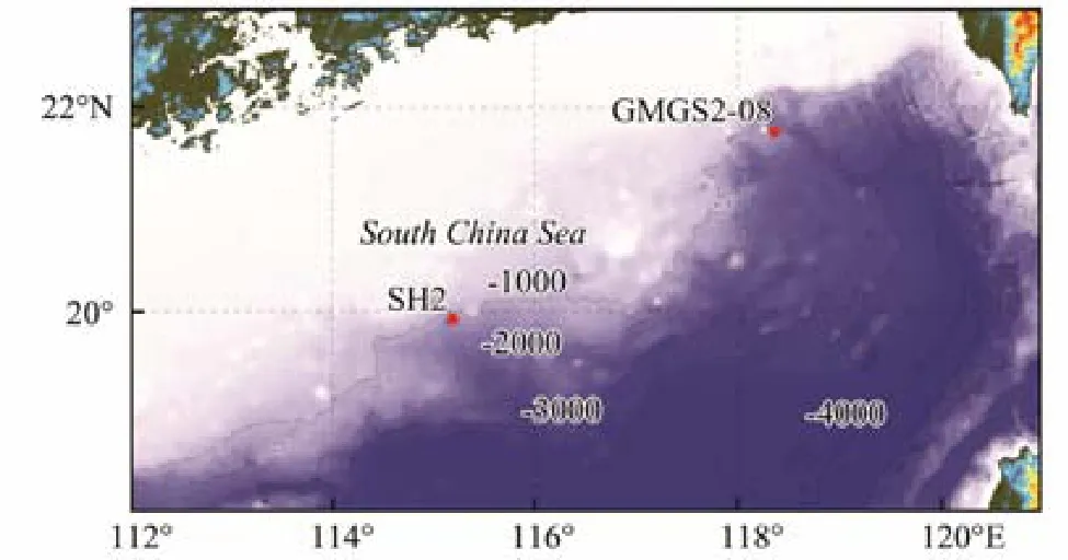
Fig.1 Sampling sites of gas hydrate used in this study.
2.2 Analytical Methods
SEM (Hitachi S-3400N) was used for the characterization of surface morphology. A cryo-preparation and coating station (Gatan ALTO 1000E) was attached to the SEM to maintain the integration of gas-hydrate samples. Before SEM observation, small sample sections (0.5 cm × 0.5 cm× 0.75 cm) were cleaved in liquid nitrogen and fixed to a sample stage. The sample stage was then transferred to the cryo-preparation and coating station. In the preparation chamber, the hydrate sample was cleaved by a builtin knife to produce a fresh fracture surface, then coated with Au-Pd. Finally, the sample stage was inserted directly from the preparation chamber into the cryo-imaging stage in the SEM column. The temperature was monitored by a thermocouple embedded in the stage just below the sample. During observation, a relatively lower accelerating voltage (3–5 kV) was used to minimize sample alteration or beam damage to the sample surface. The accelerating voltage was increased to 15 kV only for the energy dispersive X-ray spectroscopy elemental analysis (EDS).
3 Results and Discussion
3.1 Discrimination of Ice and Methane Hydrate
Since partial dissociation of gas hydrates would probably occur in the process of sampling and transportation,the residual water in the samples would form ice and disperse throughout the hydrate samples while stored in liquid nitrogen. As a result, the existence of ice in hydrate samples can hardly be avoided. Because methane hydrate and ice both have dense and smooth surfaces (Figs.2D, 2E,2F and Figs.2A, 2B, 2C), the high similarity in their microscopic morphologies would hamper the discrimination of methane hydrate from ice under an electron micro-scope.
Two methods can be efficient in distinguishing methane hydrate from ice under an electron microscope. One is to prolong the observation time (Stern et al., 2004; Stern and Kirby, 2008). Under vacuum conditions, hydrate will partially dissociate under the continuous impact of electron beam for a certain period of time (about 20 min), and the surface of hydrate will appear to be porous with a pore size of around 200–400 nm (Fig.3B). In contrast, the ice surface is relatively stable under prolonged observation(Fig.3A). The other method is to obtain, the EDS spectrum of the target sample area. As methane hydrate contains methane molecules, the spectrum of hydrate will show an obvious C element signal, and, in contrast, the signal of C element cannot be found in the spectrum of ice.
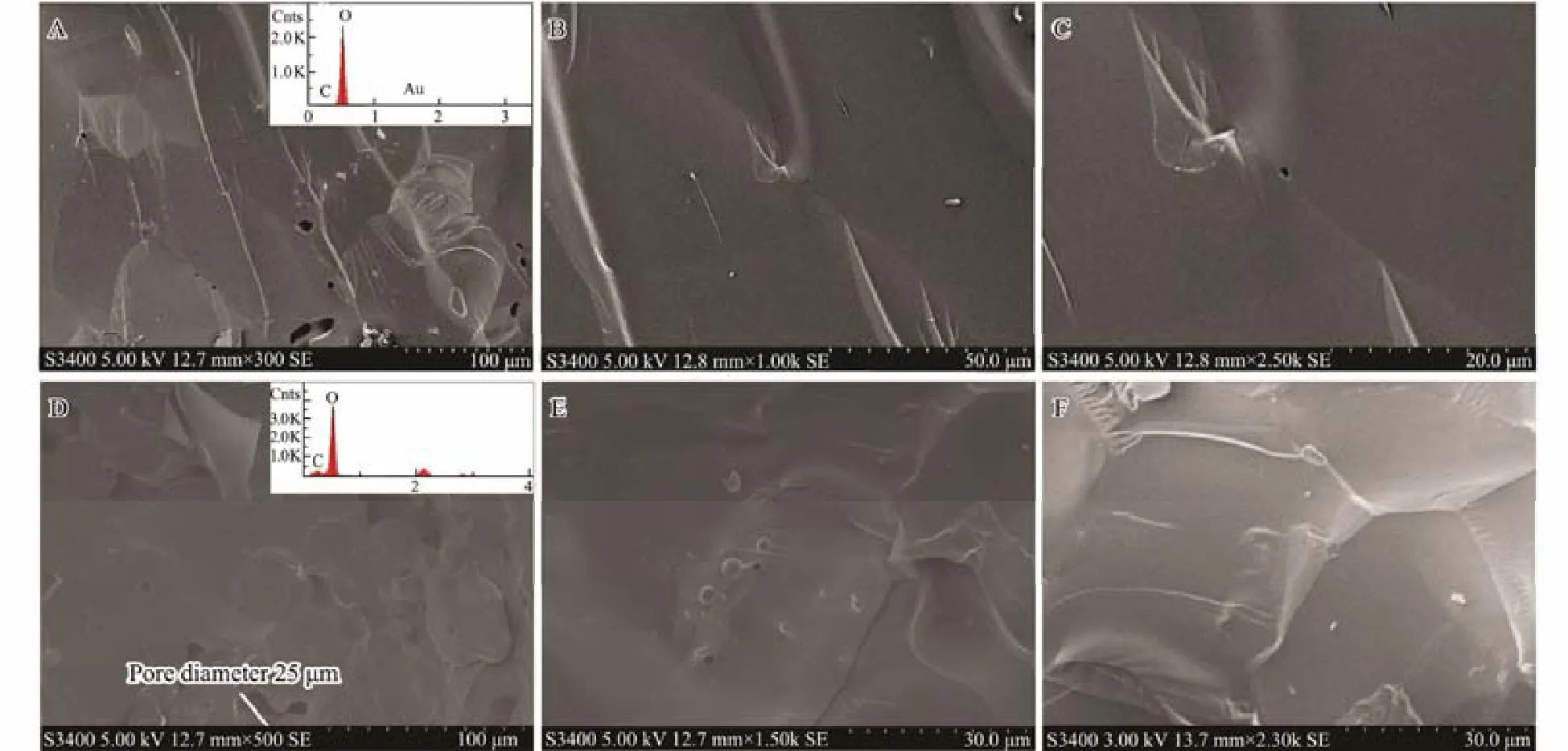
Fig.2 Surface morphology of methane hydrate and ice. A, B, C, surface morphology of ice at different magnifications (×300,×1000, ×2500) at the same sample location; D, E, F, surface morphology of methane hydrate at different magnifications(×500, ×1500, ×2300) at the same sample location on initial inspection. It is shown that both the surface of ice and methane hydrate is quite similarly dense and smooth.
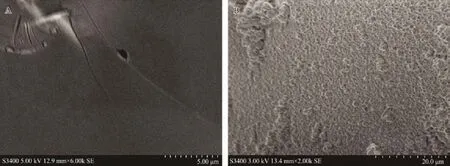
Fig.3 The surface morphology of ice and methane hydrate after 20-minute observation. A, surface of ice remained smooth and dense; B, surface of methane hydrate was dissociated by the continuous impact of the electron beam showing microporous characteristics.
3.2 Surface Morphology of Synthesized Gas Hydrates
3.2.1 Methane hydrate (sI)
Figs.2D, 2E, and 2F show the surface morphology of library-synthesized methane hydrate samples under different magnifications at the same location. The hydrate surface was relatively dense and smooth upon initial inspection right after the hydrate samples were placed into the SEM column. The relatively larger pores as shown in Fig.2D were probably formed by residual methane bubbles (Klapp et al., 2010a, 2010b). With prolongation of the observation time (20 min), the hydrate phase exhibited surface deterioration and sublimation, resulting in the appearance of a large number of micro-pores (about 200–400 nm) on the surface of methane hydrate as shown in Fig.3B. Similar to Stern’s observation of the surface morphology of ethane hydrate, the surface of ethane hydrate was also smooth at initial observation, and a micro-porous structure formed on the hydrate surface due to electron beam damage (Stern et al., 2005a) after 1 h of observation under vacuum conditions. This was somewhat different from the surface morphology of sI hydrate reported by Kuhs et al. (2000). They believed that the similar spongy microporous structures were the original nature of the hydrate surfaces, and not formed by surface deterioration in sample preparation or from the damage caused by continuous electron beam bombardment during SEM observation.
3.2.2 Isobutene hydrate (sII)
The surface morphology of isobutane hydrate under different magnifications (×300, ×1000, ×3000) at the same location at -190℃ is shown in Figs.4A, 4B, and 4C, respectively. The surface of isobutane hydrate showed a tier-like structure, and kept almost unchanged with the prolongation of observation time. This was similar to the surface morphology of the sII hydrate obtained in the Bush Hill region of the northern Gulf of Mexico as reported by Klapp et al. (2010b).
It was shown that the surface morphologies of hydrates with varied structural types were significantly different.The surface of the sI hydrate was relatively smooth, while that of the sII hydrate was tier-like, which might be caused by the different crystallization degrees of the hydrate.With higher crystallization degree as the sII hydrate, the tier-like surface structure may be formed by the edges of multiple hydrate crystals. With prolongation of the observation, there was no obvious change in the isobutene hydrate surface, which may be related to the volatility of the guest molecule of the hydrates (Klapp et al., 2010a). Compared with methane hydrate, the guest molecule of isobutane hydrate was larger and thus more difficult to volatilize. As a result, the surface of isobutane hydrate did not change much in a certain period of observation time.

Fig.4 Surface morphology of isobutane hydrate showing tier-like structure.
3.3 Surface Morphology of Gas Hydrate-Bearing Samples
3.3.1 Synthesized gas hydrate-bearing quartz sands
Since the size of quartz sands is relatively larger (ranging from 0.15 mm to 0.55 mm), the connectivity of the pore structure is relatively higher. After synthesis of methane hydrate in the quartz sands, the sample was studied using cryo-SEM. As shown in Fig.5, methane hydrate mostly formed on the surface and pores of the quartz sand particles, cementing the quartz sand particles together. Small pores with dozens of microns in size occurred in the hydrate region, which may have formed the channel of methane diffusion during hydrate formation. The microscopic morphology of the synthesized hydrate-bearing quartz sands was similar to that of the hydrate-bearing sediments collected from the Mallik Sea area, in which the hydrates also bound the sand sediment particles together (Stern et al., 2004, 2005a).
3.3.2 Natural gas hydrate-bearing sediments from the South China Sea
It has been reported that most of the gas hydrate reservoirs in the South China Sea are argillaceous sediments with a high clay content, and the hydrates are preserved in distributed, massive, veined, and nodular form in the sediments in the South China Sea, similar to those of the Andaman Sea area of the Indian Ocean (Stern and Kirby,2008; Stern and Lorenson, 2014; Liu et al., 2017).
a) Dispersed gas hydrate
Fig.6 shows the surface morphology of dispersed hydrates in dense argillaceous sediments (Shenhu area, the South China Sea). SEM observation showed that the hydrate-bearing sediments were homogeneous and compact while hydrate coexisted with sediment with no obvious stomatal distribution (Fig.6A). As shown in Figs.6A and 6B, the materials with a smooth surface were methane hydrates, while the surface of the sediment particles was uneven. Fig.6C shows the surface morphology of hydratebearing sediments after complete dissociation of gas hydrate at 20℃ (the same sample area in Fig.5A). It was shown that the porosity of sediment increased and the surface became rougher after hydrate dissociation. It was indicated that the dispersed hydrates mainly filled the pores of the sediments, and the original surface morphology of the sediments were evident after hydrate dissociation. Fig.6D shows the surface morphology of the pure methane hydrate (the area drawn by dotted line in Fig.6B).The hydrate surface was dense and smooth, which was similar to that of the lab-synthesized hydrate as shown in the above Figs.2D, 2E and 2F.
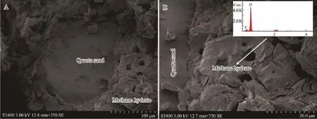
Fig.5 Occurrence of methane hydrate in quartz sands.
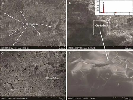
Fig.6 Surface morphology of hydrate-bearing sediments (dispersed) before (A and B), and after (C) hydrate dissociation. The central outlined box in B is expanded in D, showing the smooth surface of pure hydrate.
It has been reported that gas hydrate reservoirs with higher clay content are usually rich in foraminiferal shells,such as in the Shenhu area of the South China Sea, Ulleung basin in South Korea, and the Andaman area of the Indian Ocean (Chen et al., 2013; Li et al., 2016). As such,a large number of foraminifera were observed in the hydrate-bearing sediment samples collected from Shenhu area,the South China Sea. As shown in Fig.7, the shell of foraminifera formed a relatively large pore in the sediments,and gas hydrate accumulated in the shell. The surface morphology of the sample after hydrate dissociation is shown in Fig.7C. The structure and thickness of the foraminifera shell can be clearly seen before and after hydrate dissociation. Compared with argillaceous sediments, there were more pores and cavities in the microbial shells, which not only increased the porosity and permeability of the sediments, but also provided a place for the growth and accumulation of hydrates, thus increasing hydrate saturation.Therefore, the existence of microbial shells was beneficial to the occurrence of hydrates. Based on the change in surface morphology and pore characteristics of the gas hydrate-bearing sediments before and after the dissociation of dispersed hydrates, it was possible to estimate the hydrate saturation, which might provide a corrective reference for the reserves estimation (Stern and Lorenson,2014).
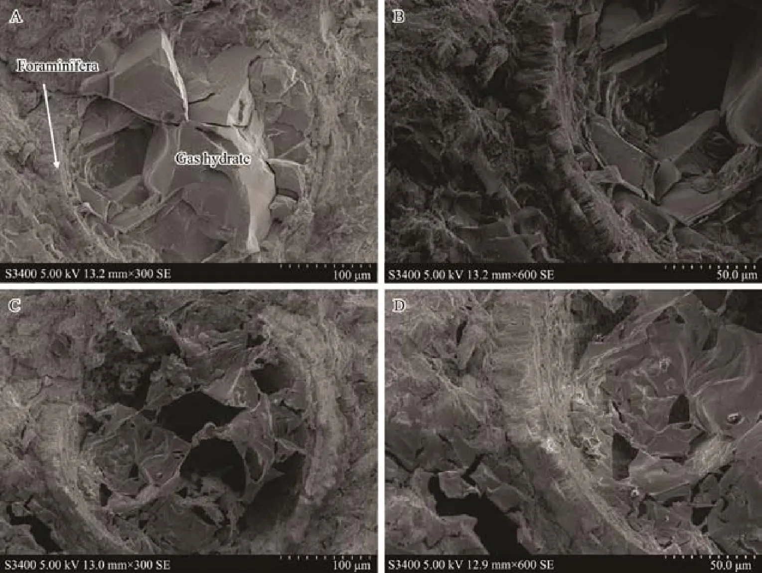
Fig.7 Surface morphology of hydrate-bearing sediment samples rich in foraminifera. A and B, before hydrate dissociation; C and D, complete dissociation of hydrate.
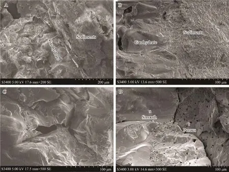
Fig.8 Surface morphology of veined and block hydrate-bearing sediment samples. A and B, sediment-hydrate contact relation of (A) veined and (B) massive hydrate-bearing sediment samples; C, surface morphology of veined hydrate in argillaceous sediments; D, surface morphology of massive hydrate in argillaceous sediments.
b) Veined and massive hydrates
Methane hydrate collected from the Pearl River Mouth Basin appeared as massive and veined in the hydratebearing sediments. Figs.8A and 8B show the contact relation between veined/massive hydrates and sediments. Owing to the different surface morphologies, hydrate and sediment were easily distinguished with an explicit boundary.
The surface morphology of the veined/massive methane hydrates (Figs.8C and 8D) exhibited two distinct characteristics: one was smooth and the other was porous (pore size ranged from several to tens of microns). As shown in Fig.8D, the S region was smooth hydrate, and the coexisting T region was porous hydrate. The distinct hydrate surface morphology may be related to the gas supply and dissolved gas volume. Once the methane gas supply was high enough, exceeding the consumption of methane gas by the formation of gas hydrate, the presence of residual methane gas in the formed gas hydrates was inevitable.As a result, the thus-formed gas hydrate was likely to show a porous structure. In contrast, when methane gas supply was low, the slow growth and accumulation of gas hydrate may form a compact and smooth surface.
3.4 Pore Structure of Hydrate
Previous studies have shown that natural methane hydrates have two distinct surface morphologies: a) dense surface, occasionally with some larger pores (several microns to tens of microns); b) sponge-like micro-porous structure (pore size is around several hundred nanometers). Hydrates of these two different characters may exist alone or simultaneously. However, only methane hydrate with the former morphology was observed in this study.Since the formation of micro-porous (about several hundred nanometers) structure requires additional surface free energy, the reason for the development of this non-equilibrium structure is still unclear. Some researchers have studied the development of the micro-porous structure(Stern et al., 2005a). By observing the processes of hydrate growth and recrystallization, it was inferred that the micro-pores (about several hundred nm) were probably temporary morphological features, occurring only in the case of early to intermediate stages of hydrate formation by the mixing of ice and gases, or, in the case of partial dissociation/sublimation and recrystallization, such as hydrate surface dissociation (Fig.3B) with prolonged testing time under high vacuum conditions. It is still questionable whether the porous structure remained stable in the geologic time scale, especially in the stable environment of the permafrost region. Moreover, the porous structure of gas hydrate may have a potential influence on the physical parameters of hydrate, such as thermal conductivity and acoustic velocity (Genov et al., 2004; Stern et al.,2004). Therefore, it is of great significance to understand the mechanism and process of micropore growth, as well as to know whether the micro-porous structure exists primitively or is caused by sampling and transportation.
4 Conclusions
The surface morphologies of hydrate may affect its physical parameters. The microscopic properties of hydrate in sediments, such as its occurrence and contact with sediments, can reflect the behavior of hydrate accumulation and dissociation. In this study, cryo-SEM was used to investigate the surface morphology of hydrate. Conclusions are made as follows:
1) Based on the SEM observation of both natural gas hydrate and lab-synthesized hydrate, the surface morphology of different types of hydrates is distinctive. The surface of methane hydrate (sI) is smooth, and the surface of isobutane hydrate (sII) is tier-like. Compared with methane hydrate, the structure of isobutene hydrate is more stable.
2) The surface morphology, pore structure, and contact relation between hydrates and sediments are different from distinct occurrence of hydrates in sediments. The hydrates in quartz sands are mainly pore-filling and cemented with quartz sand particles. Dispersed hydrates occurring in the sediments of the South China Sea grow in the pores of the sediments, and there are a large number of sedimentary microorganism shells such as foraminifera, providing favorable space for hydrate growth. The veined/massive gas hydrate-bearing samples collected from the South China Sea show a clear hydrate-sediments boundary.
3) Two distinct morphologies are observed on the surface of veined/massive hydrates: one is dense and smooth,the other is porous (several microns to tens of microns).Previously reported micro-porous (hundreds of nanometers) structure was not observed in our samples. It is considered that this structure may only exist temporarily. It is worthy of further investigation as to whether or not the micro-porous structure is stable on a geological time scale.
Acknowledgements
This study was financially supported by the National Natural Science Foundation of China (No. 41976205), the National Key R&D Program of China (No. 2018YFC031 0000) and the Open Funding of Qingdao National Laboratory for Marine Science and Technology (No. QNLM20 16ORP0203).
杂志排行
Journal of Ocean University of China的其它文章
- Abyssal Circulation in the Philippine Sea
- Numerical Study of Storm Surge Inundation in the Southwestern Hangzhou Bay Region During Typhoon Chan-Hom in 2015
- Interannual Variability and Scenarios Projection of Sea Ice in Bohai Sea Part I: Variation Characteristics and Interannual Hindcast
- Probability Distribution of the Hull Motion and Mooring Line Tension of Two Floating Systems
- Suppression of Vortex-Induced Vibration by Fairings on Marine Risers
- The Characteristics of Storm Wave Behavior and Its Effect on Cage Culture Using the ADCIRC+SWAN Model in Houshui Bay, China
