Bus Priority Control for Dynamic Exclusive Bus Lane
2019-11-07ZhiboGaoKejunLongChaoqunLiWeiWuandLeeHan
Zhibo Gao,Kejun Long,,Chaoqun Li,Wei Wu and Lee.D.Han
Abstract:One problem with the existing dynamic exclusive bus lane strategies is that bus signal priority strategies with multi-phase priority request at intersections are not adequately considered.The principle of bus signal priority level was designed based on the isolated multi-phase structure principle consideration of the bus signal priority,and a new priority approach for the dynamic exclusive bus lane was proposed.Two types of priority strategies,green extension and red truncation,were proposed for current phase and next phase buses,respectively.The control parameters including minimum green time,green extension time,maximum green time and bus arrival time are calculated.The case studies for this paper were carried out using four consecutive intersections of Huaide Middle Road in Changzhou City.The signal control scheme was designed using the conventional,exclusive bus lane method,the dynamic exclusive bus lane without signal priority method,and the proposed approach,respectively.The authors used the VISSIM simulation platform to evaluate the efficiency of each approach.Results showed that the method of approach can significantly decrease delays caused by social and conventional buses and make up for the negative impact social buses have on the bus rapid transit(BRT)operation,which allows the method to complement the dynamic,exclusive bus lane design.
Keywords:Traffic control,dynamic exclusive bus lane,signal priority control,lane operation.
1 Introduction
Dynamic exclusive bus lane is a new bus lane operation mode comparing to conventional exclusive bus lane,which refers to dynamically setting/switching the bus lane.When the bus is detected in a real time,the social vehicles is prohibited from entering the lane,when no bus is detected,social vehicles are allowed to enter the lane,thereby maximize the utilization efficiency of the bus lane[Al-Deek,Sandt,Alomari et al.(2017);Wu,Larry,Yan et al.(2018)].The concept of an Intermittent Bus Lane(IBL)was first introduced by Viegas et al.[Viegas and Lu(2001,2004)]who defined the basic concept of the IBL system,later,later,they further studied the operation characteristics and signal settings of the exclusive bus lane[Viegas and José(2006,2007)].Although some analysis results show that the efficiency of IBL is prominent,the lane design queues to exist in the bus lane,which maybe result in substantial queuing delay.To overcome this drawback,several studies[Eichler(2005);Eichler and Daganzo(2006);Guler and Cassidy(2012)]have proposed an improvement idea,called bus lane Intermittent and dynamic priority(BLIDP).The differences from the IBL proposed by Viegas is that requiring traffic to exit the bus lane reserved when a bus is present.Similarly,Carey et al.[Carey,Bauer and Giese(2009)]took real road as an example to evaluate and analyze the efficiency of the BLIP strategy through micro-simulation,and found that BLIP can improve the efficiency of bus operation about 16%.Of course,this result did not consider spatiotemporal disturbances and stochastic fluctuation characteristics of traffic flow.To contend with the impacts of traffic flow interactions,researchers have proposed using a simulation-based approach by constructing a micro-simulation model with a predetermined BLIDP mechanism.Zhu et al.[Zhu(2010);Zyryanov(2012)]focused on this shortage and proposed a method combining numerical simulation and simulation to analyze the influence of random fluctuations of traffic flow caused by random arrival and signal timing in exclusive bus lanes.Based on two-lane road section,Qiu et al.[Qiu and Li(2015)]utilized the cellular automaton theory establishes no-bus priority control and exclusive bus lane control model and proposes improvements of exclusive bus lane operation strategy.Considering the increasing popularity of in-vehicle communication equipment,Wu et al.[Wu,Larry,Ma et al.(2013);Wu,Deng,Song et al.(2017)]utilized Vehicle-to-Infrastructure(V2I)communication technology to realize the strategy of exclusive bus lane control and analysis the sensitivity of parameters,such as,vehicle equipment rate,bus departure frequency,in order to acquired main influence factors of BIIP(Bus Lanes with Intermittent Priority).
As an innovative mode of lane management,the usefulness and feasibility of dynamic exclusive bus lane have been proved by many studies and will become an important method of lane management.However,due to this mode belongs to innovative mode,its settings rely on hardware technology foundation of Cooperative Vehicle Infrastructure System(CVIS).Therefore,the existing exclusive bus lane examples are rarely,many studies mainly focus on bus lane design,a few researches about priority control in the condition of exclusive bus lane.At the present,with the improvement of CVIS,Carlive Chain(IOV)and big data technology,the operation mode of exclusive bus lane will break through the constraint of original V2I communication technology[Xiang,Shen,Qin et al.(2018);Zeng,Dai,Li et al.(2018)].To this end,the study of the operation mechanism of exclusive bus lane and the signal priority control strategy will provide theoretical basis for scientific and rational request of exclusive bus lane.It can also improve the urban lane management level of China.
In this paper,we design a multi-phase bus signal priority control strategy based on multiphase structure principle consideration of the bus signal priority,in order to analyze and evaluate the operation characteristics and control effects of dynamic exclusive bus lane under adopt multi-phase bus signal priority strategy,so as to improve the utilization rate of bus lanes.
2 Operating rules of exclusive bus lanes
Dynamic exclusive bus lane consists of three basic concepts and parameters:clearance area,open rules and clearance rules.Taking the one-way three lanes and the rightmost exclusive bus lane as an example,the related concepts are explained.
Clearance area:Divide the bus lane into equal length sections and follow the “clearance rules” and “open rules” in open area,as shown in the following Fig.1.

Figure 1:The diagram of clearance area in dynamic exclusive bus lane
Open rules:When no bus arrival,open exclusive bus lane to special types of vehicles,such as taxis,buses,school buses,carpool,ordinary cars etc.
Clearance rules:When the bus arrives,the social vehicles in the exclusive bus lane are cleared,including:no entry,normal driving or lane change.
In order to achieve rules of open and clear,amber flashing light and VMS(Variable Message Sign)are installed on both sides of exclusive bus lane and installed vehicle detectors on both sides of clearance area.When bus enter into clearance area and the amber light flashing,to prohibit social vehicles into bus lane.In the case of traffic congestion,the amber light flashing in advance to prohibit social vehicles from entering,so as to ensure the right-of-way of the bus.At the same time,VMS can guide social vehicles enter or departure bus lane as shown in Fig.2.
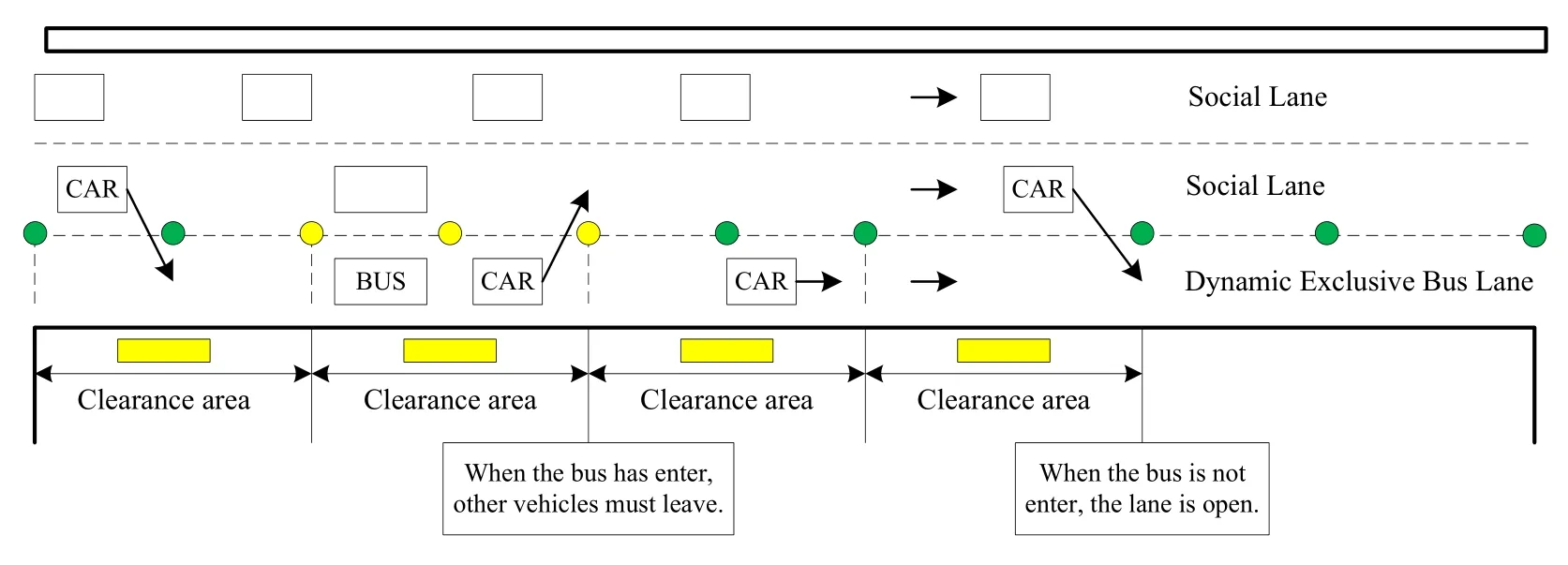
Figure 2:The diagram of open and clearance rules in dynamic exclusive bus lane
The operation rules are as follows:
(1)After the bus enters the clearance area or before it leaves,the object lane in clearance area is set for exclusive bus lane and VMS inform other vehicles are not allowed to enter the lane.
(2)Before the bus enter clearance area or after it leaves,the object lane in clearance area is set for ordinary lane then VMS inform other vehicles drive into the lane.
(3)When social vehicles are requested departure the bus lane,but adjacent lane not have enough spaces to meet safety lane change of other vehicles until find enough spaces to achieve lane change,social vehicles can still drive on the bus lane.
(4)When social vehicles enter the bus lane and if there no enough spaces to meet it achieve lane change,but still allow social vehicles into the entrance of the bus lane.After social vehicles passes the intersection then depart from the bus lane.
(5)When buses or social vehicles have an accident on exclusive bus lane,the upstream vehicles are guided to bypass by using VMS;the exclusive bus lane function is recovered after the accident is dealt with.
3 Transit signal priority signal timing
3.1 Structure of signal timing phase
The NEMA(National Electrical Manufactures Association)standard proposed by the National Electrical Manufactures Association is relatively mature method of phase design for traffic signal control at present,and most theoretical researches and practical request adopt NEMA double loop phase sequence rules[Gartner and Stamatiadis(2002);Head,Gettman and Wei(2006)].The 8-phase structure is taken as an example to design a double-ring phase structure for bus priority control,as shown in Fig.3.

Figure 3:The structure of phase
In Fig.3,ring is composed of two or more temporally coherent but incompatible conflicting phases,and is arranged in a certain order.The sequence of conflicting phases,which is continuously arranged,between the two barriers is called half semi-ring.The position at which the phase conflict between different approach lanes under multipleseparated rings is called barrier.The semi-ring that contains the bus phase is called Bus semi-ring,and the other one that does not contain the bus phase is called Non-bus semi-ring.
The phase switching principle of the double-ring structure is as follows:if the green light phase is in the front phase of the barrier and both the current green light phase and the concurrent phase reach the respective green light termination conditions,the phase switching can be performed simultaneously.If the green light phase is not in the front phase of the barrier,the phase can switch until the current green light termination time.
3.2 Multi-phase transit priority control logic
3.2.1 Priority determination principle
When many phases apply for bus priority may lead to conflicts of priority plans,so it is necessary to determining bus priority level of each phase,the determination principle of multi-phase transit priority level as follows:
(1)Priority level of request
According to the principle of “Near Green Light”[Bie,Wang,Zhao et al.(2013);Ding,Zhang and Qian(2015)],different levels are assigned to each priority request.Specifically,the priority level of bus that arrives in green light phase is higher than that in non-green light phase.The closer the arrival time is to the next green light phase,the higher the priority level for the bus arriving at the red light phase.The earlier of arrival time,the higher of priority level for the bus arriving at the same phase.
(2)Priority level of control decision
The priority level of green extension strategy is higher than red truncation control strategy,that is,in the same phase,buses that arrive at green time and red time apply for priority simultaneously,the priority level of green extension of former is higher than red truncation control of latter
3.2.2 Control logic design
(1)Logic of total control
Multi-phase transit priority control logic consists logic of total control and logic of control decision.The logic of total control response for evaluating the current traffic state,when meet certain conditions then execute corresponding control module(green extension and red truncation)respectively.The basic process of total control is as follows:
1)The information of bus speed and position under each phase acquired in real-time and predict the arrival time of bus that has been triggered the priority request,then determined sequence of bus priority level according to determination principle of bus priority level at each phase.
2)If there is no bus priority request in the current phase then carry out original traffic signal scheme.Otherwise green-extension or red truncation is given to priority request vehicles of highest priority level at present phase.If the bus arrival time within the minimum green light time of the phase then retain the request;and if the bus arrives at the minimum green light time and maximum green light time in the phase,the greenextension strategy will be given,otherwise the red truncation strategy will be given.
3)Make decision analysis of planned measures for each phase.According to the principle of phase priority level and take the current display green light phase into consideration firstly,if there is red truncation strategy in the current green light phase then reserve bus priority request of subsequent phase,and carry out green light extension control module;otherwise transfer into(4).
4)The current display green phase includes the red truncation strategy,and if subsequent phase exists green-extension strategy,then implement green-extension control module for subsequent phase,and current green light phase bus priority request be reserved,otherwise,the red truncation control module will be implemented for the current green phase.
(2)Green extension control strategy
The function green-extension control module is to decide whether execute greenextension control process for the current phase,according to the time of bus arrives at stop-bar,when bus arrives at the current green light phase.The control process of greenextension module as follows in Fig.4.

Figure 4:The diagram of green extension control module
Predicting the arrival time of the bus at the current green light phasei.The time of bus arrives at stop-bar within the minimum green time of phasei,it need not change signal,and bus can pass through intersection directly and the priority request of the bus is removed,otherwise calculate the green extension time in bus phase.If the extended green time is less than the maximum green light time then reserve the priority request of the bus and extend the unit green time;otherwise,remove the current bus priority request and switch the current green phase.
(3)Red truncation control strategy
The function of this module is to shorten the current phase green light time and turn on the next phase green light ahead of time,when the current phase no bus arrive and other phases has bus.The process of red truncation control module as shown in Fig.5.

Figure 5:The diagram of red truncation control module
Predicting next display green phase whether is bus priority request phase at the current green light phasei,ifit is,then judge the time of bus arrives at stop-bar whether greater than the end time of minimum green light of phasei.Ifit is larger,then reserve the bus priority request,otherwise,remove the priority request.When meet bus priority request conditions then judge the green time of phaseiwhether greater than minimum green time,ifit is,then switch the phaseiand implement red truncation strategy for next phase,otherwise,to the next bus priority request.
3.3 Determination of control parameters
Based on above control logic,the main control parameters of this model includes:minimum green time,maximum green time,unit green time,bus arrival time.The determination methods of these parameters are described in the next.
(1)Minimum green timeGmin
The minimum green time not only can assure motor vehicles that are queued during the last red light phase pass through intersection successfully but also guarantee the safety of pedestrians crossing the street.So the minimum green time determined by vehicles minimum green timegmin1and minimum green time of pedestrian crossinggmin2。
In the state of undersaturation,the minimum green timegmin1of motor vehicles can determined by the evacuation time of vehicle queuets::

where,Qqueueis maximum number of queued vehicles of entrance road;qsis saturation flow rate of entrance road;qiis arrival rate of entrance road.
At the same time,according to computation method of HCM for minimum green time of pedestrian crossing:

where,Lpis distance from pavement to safety facilities such as the nearest pavement,pedestrian safety island,and traffic island;Vpis the velocity of pedestrian,range from 1.0 m/s to 1.5 m/s;Iis inter-green time,5 s generally.
Hence,the minimum green timeGminas follows:

(2)Green extension timeGext
Unit green extension time is associated with the distance from detectors to stop-bar,and ensure in the safety traffic condition reduce the loss of green time,to improve operation efficiency of actuated control,as follows:

where,L is distance between detector and stop-bar andis average speed of vehicles.
(3)Maximum green timeGmax
Maximum green time determined by optimal cycle times and green signal ratio in fixedtime control so that ensure optimal green signal ratio.When transit phase reaches maximum green time,the green light forced to end and next phase switched.In this paper maximum green time extension should be greater than or equal to the sum of green time extension and minimum green time.

(4)Bus arrival time
The bus with GPS module can detect the information of bus position and speed in real time and predict the time when the bus arrives at the stop-bar by bus travel time and stop time.The time of busiarrives at stop-bar is:

where,tiis the time of busiarrives at stop-bar;is the travel time of busifrom detector to stop-bar;is the stop time of busi.
4 Case study
4.1 The present status of case
Huaide Middle Road,Changzhou City,Jiangsu Province is a main road through the city.This road is two-way eight-lane roads with a central isolation belt.Three social lanes and a bus lane are set on one side,three social lanes are for cars and ordinary buses.The bus lane on the leftmost side only allows BRT vehicles at present.There are total five BRT bus stations and five ordinary stations on this road,the layout as follows in Fig.6.
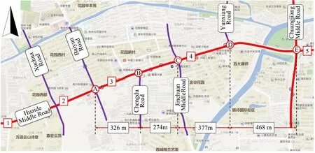
Figure 6:The layout of intersections along Huaide Middle Road
The intersections along the road are:Baiyun Road(A),Chendu Road(B),Jingchuan Middle Road(C),Yunxiang Road(D),and Changjiang Middle Road(E).The current signal control timing scheme is as follow:

Table 1:The current signal control timing scheme

C Jingchuan107 3 0 50 28 29 Middle Road D Yunxiang87 2 87 66 21 Road E Changjiang173 4 9 70 33 32 38 Middle Road
The existing BRT Bus Rapid Transit Line 2,with five BRT stations and average departure interval is 5min of per vehicle,the five BRT stations are:Garden Bus Center Station 1,Jingu Garden 2,Magong Bridge 3,Guibin Bridge 4,Huaide Bridge 5;at the same time,five bus stops and 10 bus routes are set up.The present status of bus stations and routes as follows in Tab.2.

Table 2:Route layout of each conventional bus station
At the present,the bus lane is exclusive right-of-way of BRT vehicles,which does not allow social vehicles and conventional buses entry.The utilization rate of the bus lane very low and social benefits are not fully developed.In order to improve the utilization rate of the bus lane,we consider change BRT lane in the innermost into exclusive bus lane.The BRT lane after be rebuild should follow the operation rule of exclusive bus lane based on fixed distance VMS:social vehicles and conventional buses are allowed into the bus lane before BRT drive into the clearance area,when the BRT vehicle into the clearance area,social vehicles and conventional buses should departure the clearance area.If there is no enough safety spaces for adjacent lane social vehicles and conventional buses can continue drive in the bus lane until enough space the leave the bus lane.
4.2 Simulation
Choosing the delay of BRT,social vehicles and conventional buses as evaluate indicators.The simulation experiment developed by the simulation platform based on VISS5.3 and C++programming environment.C++programming environment uses Microsoft Visual Studio2008,VISSINM and C++programming environment connected by COM interface of VISSIM.Firstly,call the vehicle,link,detector,signal group and other object function access simulation environment and initialize the simulation parameters then start simulation.Secondly,VISSIM COM interface is used to collect vehicle operation state in real-time,and exclusive bus lane and signal single bus priority control module are carried respectively,to realize the open and closing of the exclusive bus lane at different states,in order to adjust intersection's signal timing scheme.Lastly,running simulation until the end time then output and save simulation experiment data.The specific simulation process is shown in Fig.7.
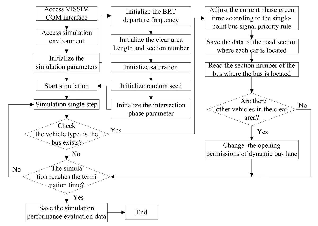
Figure 7:The diagram of simulation process
4.3 Evaluation of proposed method
In order to test the operation benefits of the method proposed by this paper,comparing conventional bus lane scheme with exclusive bus lane scheme(without signal priority).The schemes are described as follow:
Scheme 1:conventional exclusive bus lane scheme.In this scheme,BRT has own right of-way and other vehicles are not allowed travel in the bus lane.
Scheme 2:dynamic exclusive bus lane scheme without signal priority.This scheme is exclusive bus lane control strategy based on fixed distance VMS,clearance area distance is main control parameter of this paper and settled 300 m in simulation experiment.
Proposed scheme:dynamic exclusive bus lane scheme with signal priority control.The scheme of this paper is introduces bus signal priority control on the basis of Scheme 2,so the distance of clearance area is set to 300 m,and the main control parameters of bus signal priority strategy are shown in Tab.3.
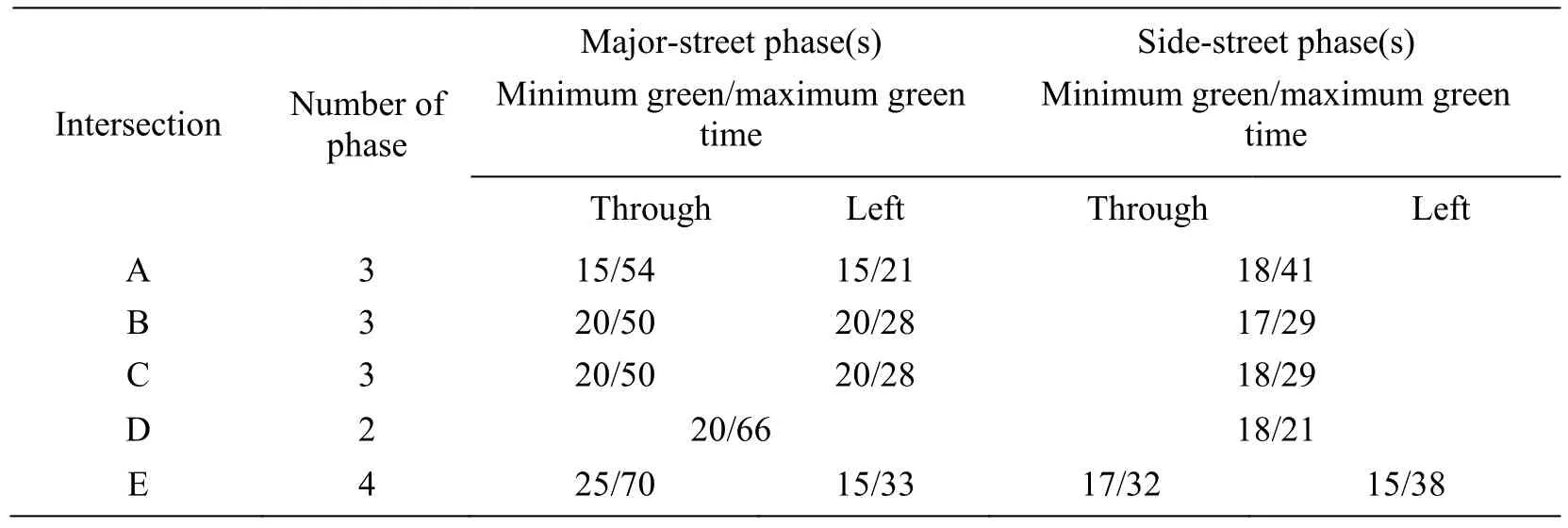
Table 3:Signal control parameters of each intersection
In the above three schemes,the departure frequency of BRT is set to 5min/vehand select different saturation rate for simulation experiment.Each simulation runs for 4100 s,the first 500 s is the simulation warm-up period and the delays of social vehicles,conventional buses and BRT vehicles that on the arterial are evaluated during periods of 500-4100 s.The simulation results shown in Fig.8.
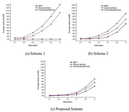
Figure 8:Comparison results of average delay between different schemes
As shown in Fig.8,with the increase of saturation,in addition to BRT travel time not influenced in Scheme 1,the delay of social vehicles,conventional buses and BRT vehicles are increased in other schemes.When the saturation less than 0.7,the delay of all types of vehicles are slowly increased in the three schemes,because at that time road capacity can meet the traffic demand of social vehicles,conventional buses and BRT vehicles.When the saturation over 0.7,the delays of social vehicles,conventional buses are increased significantly both in scheme1 and Scheme 2 while increased slowly in the scheme proposed by this paper.In order to quantify the benefits of the scheme specifically,the delays of three schemes are selected to comparative analyze with saturation is 0.7,as shown in Fig.9.Compared with scheme1 and Scheme 2,the proposed scheme can reduce social vehicle's delay by 47.9% and 30.7% respectively,and the reduction of conventional bus's delay by 58.3% and 39.7%respectively.The proposed scheme compares with scheme 1,the delay of BRT increased by 23.5%,while compares with Scheme 2,the delay of BRT decreased by 21.5%.because at a higher level of saturation,non-bus lane in scheme 1 cannot meet traffic demand of social vehicles and conventional buses,and the resource of bus lane are not be fully used;compared with Scheme 1,Scheme 2 can reduce the delays of social vehicles and conventional buses to some extent,but due to lack of enough safety spaces,social vehicles cannot departure exclusive bus lane in time,it will increase the travel delay of BRT;and compared with Scheme 2,the priority control strategy of bus signal adopted by the proposed scheme can either reduce the delay of social vehicles and conventional buses,it also can make up for the negative impact of social vehicles on the delay of BRT travel to some extent,it is a supplement and improvement to Scheme 2.
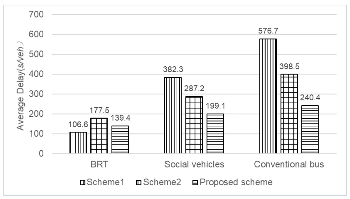
Figure 9:The Average vehicle delay when saturation is 0.7
4.4 Sensitivity analysis
In order to research operation characteristics of bus signal priority control strategy of exclusive bus lane,this paper do sensitivity analysis of parameters,such as clearance area distance and the frequency of bus departure.
(1)Clearance area distance
Based on above analysis,the proposed scheme is apply to the traffic condition of saturation over 0.7.In the analysis of clearance area distance sensitivity,the saturation set to 0.7 and 0.9 respectively and the BRT departure frequency set to 5min/veh,and choose different clearance area distance for simulation evaluate.
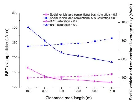
Figure 10:The average delay under different clear length
From Fig.10 shows that the delay of BRT will be decreased with the increase of clearance area distance under any level of saturation.While the delays of social vehicles and conventional buses are increased with the increased of clearance area distance.When the distance of the clearance area is 300~500 m,the BRT delay is the fastest;when it is greater than 700 m,the BRT delay is slower;when it is close to infinity,the exclusive bus lane obtains the exclusive right-of-way,which is equivalent to the conventional bus lane.The above analysis shows that,when the saturation over 0.7 and the distance of clearance area is set to 300-500mcan meet the clearance rules of social vehicles,so as to reduce the delay of social vehicles and conventional buses to improve the utilization rate of overall road traffic resources on the premise of not influence BRT.
(2)BRT departure frequency
The saturation is set to 0.7,the range of clearance area distance is set to 100-1100m,and BRT departure frequency is set to 3min/veh,5min/veh,7min/veh,9min/veh,11min/veh,13min/vehrespectively.The simulation results as shown in Fig.14,and the delay of BRT represents by solid line and dotted line represents other vehicle's delay(total average delay of car and conventional bus)
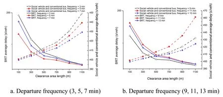
Figure 11:The average delay analysis under different departure frequency
From Fig.11,with the increased of clearance area distance,there is no significant changes of average delay of BRT with different frequency compares with other vehicle's average delay.This also indicate that the proposed method applies to the traffic condition of saturation over 0.7 and clearance area distance between 300 m-500 m.
5 Conclusion
In view of low utilization rate of exclusive bus lane capacity at the present,this paper presents a multi-phase transit signal priority control strategy based on multi-phase structure principle consideration of the bus signal priority.We also design Logic of total control and logic of control decision(green-extension and red truncation),and combined with domestic actual cases,design related experiments,and carried out experimental evaluation of the proposed control strategy.The simulation results indicate that,when the saturation is set to 0.7,the clearance area distance is set to 300 m,the frequency of BRT departure is set to 5min/veh,the proposed method can reduce the delay of social vehicles by 47.9%,30.7% respectively,and the delay of conventional bus can be decreased by 58.3% and 39.7% respectively,compares with the strategy of conventional bus and the strategy of exclusive bus lane without priority control.Through the analysis of parameters sensitivity of the model,the proposed method applies to the traffic condition of saturation over 0.7 and clearance area distance between 300m-500m.However,this paper selects a few influence parameters for analyze operation characteristics,such as saturation,clearance area distance and BRT departure frequency,and only take bus departure frequency on one-way into consideration,the bus departure frequency and the coverage of line very low.The next research step is implement the proposed strategy on multiple bus lane.
Acknowledgement:This research was funded by National Natural Science Foundation of China(NSFC),grant number 51678076,Hunan Provincial Key Laboratory of Smart Roadway and Cooperative Vehicle-Infrastructure Systems,grant number 2017TP1016.
杂志排行
Computers Materials&Continua的其它文章
- Examining the Impacts of Key Influencers on Community Development
- Parkinson's Disease Detection Using Biogeography-Based Optimization
- A Correlation Coefficient Approach for Evaluation of Stiffness Degradation of Beams Under Moving Load
- Design of Working Model of Steering,Accelerating and Braking Control for Autonomous Parking Vehicle
- Modeling and Predicting of News Popularity in Social Media Sources
- Smart Security Framework for Educational Institutions Using Internet of Things(IoT)
