Speed profile optimization of catenary-free electric trains with lithium-ion batteries
2019-09-16NimaGhavihaMarkusBohlinChristerHolmbergErikDahlquist
Nima Ghaviha· Markus Bohlin · Christer Holmberg · Erik Dahlquist
Abstract Catenary-free operated electric trains, as one of the recent technologies in railway transportation, has opened a new field of research: speed profile optimization and energy optimal operation of catenary-free operated electric trains.A well-formulated solution for this problem should consider the characteristics of the energy storage device using validated models and methods. This paper discusses the consideration of the lithium-ion battery behavior in the problem of speed profile optimization of catenary-free operated electric trains. We combine the single mass point train model with an electrical battery model and apply a dynamic programming approach to minimize the charge taken from the battery during the catenary-free operation. The models and the method are validated and evaluated against experimental data gathered from the test runs of an actual battery-driven train tested in Essex, UK. The results show a significant potential in energy saving.Moreover,we show that the optimum speed profiles generated using our approach consume less charge from the battery compared to the previous approaches.
Keywords Electric train·Catenary-free operation·Speed profile optimization · Energy efficiency
1 Introduction
In the recent years,there has been an increasing interest in catenary-free operated electric trains equipped with onboard energy storage devices. Catenary-free operated electric trains can minimize the cost by reducing the maintenance and installation costs of the catenary system and at the same time benefit from the high efficiency of the electric traction system.
There are already light rail vehicles(LRV)such as short distance metro trains or trams with on-board energy storage devices in service (see, e.g., [1]). However, the concept of the catenary-free operation of medium sized electric multiple units(EMU)with on-board energy storage devices for intercity operations remains mostly in the prototype phase or short distances[2].An exception is a battery-driven train operated by East Japan Railway Company. In 2014, East Japan Railway Company introduced a battery train equipped with lithium-ion batteries; the train is equipped with 190 kWh batteries and can go up to 100 km/h and run approximately 20 km in catenary-free operation [3].
A major challenge in designing a catenary-free EMU is the sizing of the batteries, since both the weight of the vehicle and the longer distance that the vehicle needs to run in catenary-free mode requires batteries with both high energy capacity and high power output. Moreover, a standard regenerative brake system is not always sufficient for charging the batteries,and charging stations are needed.The charging stations should further be capable of charging the batteries in a short time. Fast charging stations for the battery trains are already developed[4],and train units are becoming more energy efficient than before.In spite of the recent developments in designing charging stations and increasing efficiency in train units, energy optimal operation procedures are still crucial for battery-driven trains.According to Al-Ezee et al. [5], energy management systems are needed to monitor the state of charge and optimize the usage of the batteries during catenary-free operation.The general focus of this paper is on including the battery characteristic in the problem of energy optimal operation and verifying the results with experimental evaluations.
2 Related work and contributions
For around five decades, studies have been performed on energy-efficient train operation for electric and diesel trains(see, e.g., [6-12]). The proposed solutions cover a wide range of applications from diesel heavy haul trains (e.g.,[13])to multiple-train operation(e.g.,[14-16]).Apart from the methodological research in this field, there has also been research on designing driver advisory systems based on mathematical formulations and optimizations (see e.g.,[17]). Hybrid electric trains have also been studied for the speed profile optimization. Miyatake and Matsuda [18]proposed an algorithm based on sequential quadratic programming for energy-efficient operation of hybrid electric trains with an on-board electric double-layered capacitor(EDLC)as the secondary energy source beside the catenary systems.Iannuzzi and Tricoli[19]also proposed an energy management control strategy for a similar train configuration with supercapacitors as the secondary energy source.Sumpavakup et al.[20]presented an approach to minimize the power consumption on the substation through optimizing the use of on-board supercapacitors on the train during the operation.A comprehensive review on different energy-efficient train control methods is provided by Scheepmaker et al. [21].
Although the energy-efficient train operation is a well studied subject, due to the immaturity of the technology,literature is sparse regarding the energy-efficient catenaryfree operation of EMUs.Miyatake and Haga [22]assumed an EDLC as the on-board energy storage for an LRV and solved the energy-efficient catenary-free operation problem using dynamic programming by minimizing the electric power at the capacitors as the objective function. Colak et al. [23] considered the problem as a coast control problem and used particle swarm optimization to find the optimum coasting points for the catenary-free operation of LRVs with an EDLC as the on-board energy storage device. Li et al. [24] proposed a charging strategy for onboard supercapacitors during the catenary-free operation to improve the dynamic performance and the reliability of the charging system. Ishino et al. [25] studied the effects of charging and running time on energy-efficient operating strategies for an LRV with an on-board EDLC. Miyatake and Ko [26] presented three solutions for energy-efficient train control problem based on dynamic programming,gradient method and sequential quadratic programming and argued that they can also be used for the catenary-free operation;the energy storage device used in the simulation done by Miyatake and Ko is also assumed to be an EDLC.
Most of the research done under the subject of energyefficient catenary-free operation of electric trains consider an ELDC or a supercapacitor as the energy storage device.EDLC can provide high power and fast charge/discharge time. But on the other hand, it suffers from the extreme voltage drop and low energy density. Hence, it is used for LRVs such as trams with low speed[27].The few available intercity catenary-free EMUs use lithium-ion batteries or fuel cells as the energy storage device, which have different behavior than ELDCs or supercapacitors [28-30].
A model of the behavior of the battery can be used to consider the battery characteristics for the problem of speed profile optimization. Battery models are divided in three categories of mathematical, electrochemical, and electrical models [31]. Mathematical models are categorized in two groups of stochastic models (that are mostly based on Markov Chain, e.g., see [32]) and analytical models (e.g., [33]). Electrochemical battery models use electrochemical equations to model the behavior of each cell. Since these types of models are physics-based, they can provide information on the full dynamic behavior of the battery. But they use a set of partial differential equations, which makes them too complex for fast simulation purposes. According to Fotouhi et al. [34], reduced-order electrochemical models and electrical models are the best choices for the energy management application. Reducedorder electrochemical models are basically a simplification of the complex electrochemical models.Hence,in order to generate such models, an accurate high-fidelity electrochemical model needs to be generated, which can be a complex procedure. Electrical battery models on the other hand use different electrical components (e.g., capacitors and resistors) to build an electrical circuit with a behavior similar to the battery. These models provide enough accuracy needed for the battery management application,while avoiding unnecessary complexities of the electrochemical models [34]. Due to their simplicity, electrical models are widely used for battery management applications, such as the application for electrical vehicles (e.g.,[35, 36]) and even hybrid propulsion systems for aviation purposes [37, 38]. Electrical models have also been used for other applications such as the modeling of renewable energy systems [39]. An overview on different electrical models is presented by Mousavi and Nikdel [40].
Energy-efficient catenary-free operation of EMUs with lithium-ion batteries differs from the case where a supercapacitor or an EDLC is used, as the dynamic behavior of capacitors is different from lithium-ion batteries [41]. In the literature, there is no consideration of dynamic battery characteristics for the problem of speed profile optimization.The only exception is the research presented by Noda and Miyatake[27],in which the dynamic characteristics of the lithium-ion batteries are considered using a fitted function from the battery supplier’s discharge curve. Noda and Miyatake[27]also note that one of the next steps in the field of energy optimal operation of catenary-free operated electric trains is to present a relationship between the travel time and energy consumption. Furthermore, all of the solutions for the problem of speed profile optimization of catenary-free battery trains minimize the energy consumption in kWh on the battery (e.g., DC link) as the objective function, which is calculated based on the mechanical power calculation. But the mechanical power calculation does not provide the best solution as it does not consider the dynamic behavior of the battery (i.e., voltage fluctuation). Most importantly, there are no experimental evaluations of the methods presented in the literature for the speed profile operation during the catenary-free operation.
In this paper, we consider the characteristics of the battery in the problem of speed profile optimization for catenary-free operated battery trains. Since one of the few available intercity catenary-free EMUs is equipped with lithium-ion batteries, we consider the problem of speed profile optimization with such batteries as energy storage device. The problem will be different with other energy storage devices,such as supercapacitors.We use a dynamic programming approach,which was previously used for the speed profile optimization without the consideration of the battery behavior [42],and modify the models and objective function to consider the characteristics of the lithium-ion battery. We also evaluate our solution using experimental measurements of an actual battery train during the catenary-free operation. More specifically, based on the knowledge gaps presented in the previous section, the contributions of this work are as it follows:
· We present a method to estimate the state of charge of the battery for the speed profile optimization.For this purpose,we combine the single mass point train model with an electrical battery model.The method is later on used in a dynamic programming approach for the speed profile optimization of battery-driven electric trains during the catenary-free operation. We minimize the charge taken from the battery instead of the energy consumption in kWh as the objective and show that our approach will result in more energy-efficient speed profiles.
· The method and battery models used for the estimation of state of charge are validated against the measurements from the test runs of an actual battery-driven train.We also evaluate the performance of the dynamic programming approach and measure the potential energy saving against the actual test runs of the train.This is the first experimental evaluation of an energy optimal strategy for the catenary-free operated electric trains against measured values.
Table 1 shows a comparison between the research presented in the literature in the field of energy optimal operation of catenary-free operated electric trains and theresearch presented in this article. It is to be noted that optimizing the life cycle of the battery through the optimum speed profile opens a new optimization problem which is out of the scope of this paper.
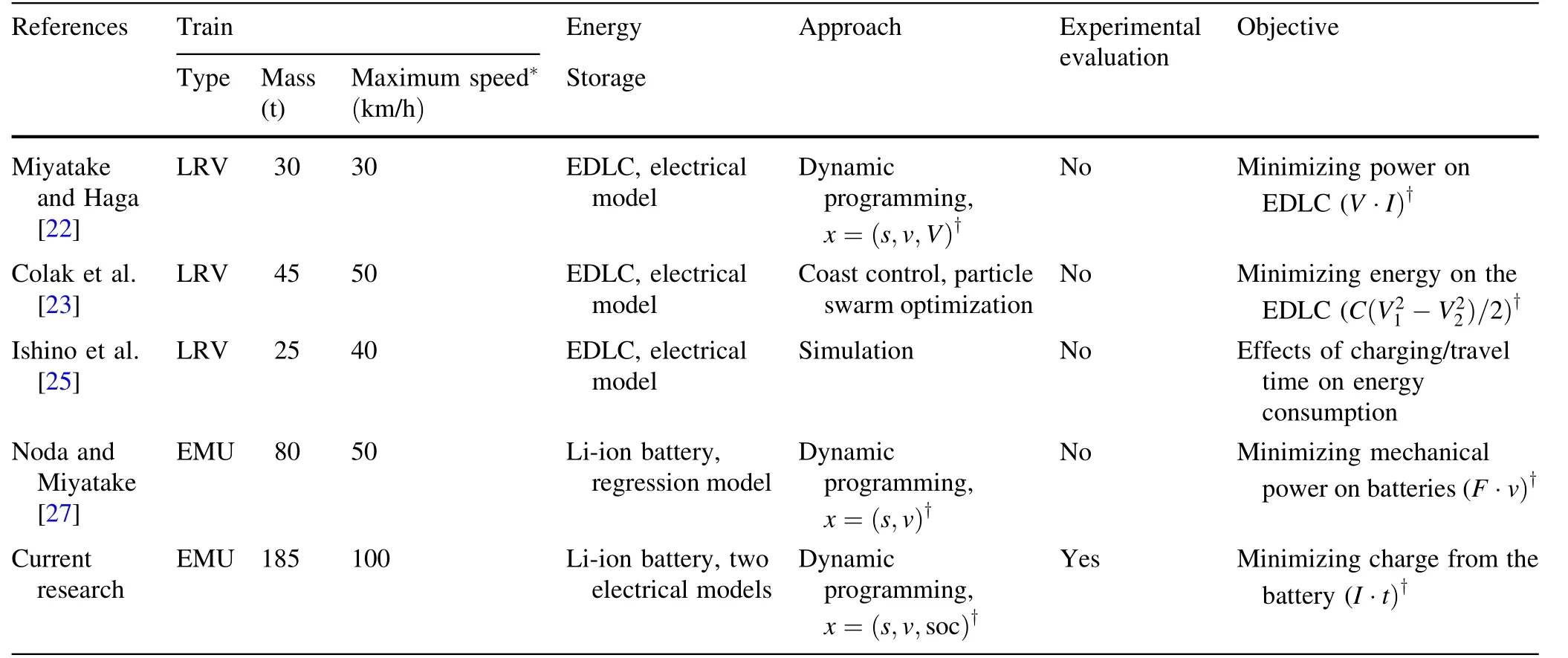
Table 1 Summary of the research presented in the field of energy optimal operation of catenary-free operated electric trains compared to the current paper
The rest of the paper is as it follows: In Sect. 3, we present the optimization approach together with a model and method for estimating the state of charge. We first summarize the dynamic programming approach used for the speed profile optimization of electric trains together with a description of the modifications needed for the problem with the battery-driven trains (Sect. 3.1). Considering the dynamic programming approach,we present a model and an approach for estimating the state of charge for the speed profile optimization in Sect. 3.2. The approach requires a battery model.Two battery models are suggested for this purpose in Sect. 3.3. Section 4 includes the experimental validation and evaluation using measurements from the test runs of an actual battery-driven train. We use a battery-driven train designed by Bombardier Transportation and tested in UK as the experimental case for our evaluations. We first validate the suggested battery models and the method for estimation of the state of charge in Sect. 4.1. Further, we evaluate the results of the dynamic programming approach against the test runs of the battery-driven train in Sect. 4.2. The paper continues with discussions on the method for the estimation of the state of charge and the optimization approach in Sect. 5. Section 5 also includes a discussion on the choice of the objective function.We end the paper with an overall conclusion and a short discussion on the future work in Sect. 6.
3 Optimization and system modeling
In this paper, we use dynamic programming as the optimization technique for the speed profile optimization. The methodology to apply dynamic programming for the speed profile optimization and its application for designing a driver advisory system is presented by Ghaviha et al. [17].The basics of the same method have been used to solve the problem of speed profile optimization for catenary-free operated EMUs using the objective function of minimizing energy consumption on the DC link [42]. Ghaviha et al.[42] did not consider the behavior of the battery, nor did they have any experimental evaluation of their results.The same approach is used in this paper as the basis for the speed profile optimization considering the characteristics of the battery. Here, we briefly present the approach introduced by Ghaviha et al. [17, 42] and we further present the modifications needed for the consideration of the battery characteristics. The final approach uses the state of charge of the battery as an input variable. Hence, we present a method to estimate the state of charge for our application, which represents a propulsion system model for the speed profile optimization of battery trains.Finally,we present two battery models suitable for our application.
3.1 Optimization technique
For the dynamic programming approach in this research,we assume travel time as the horizon and total charge from the battery as the cost function. In other words, the aim is to minimize the charge taken from the battery over the travel time.
Let xkbe state of the system and ukbe the control variable at time step k.Dynamics of the system are defined using function f, presented in Eq. (1):

For the case of the battery-driven electric train, the state variable(i.e.,xk)is defined using three variables of distance(sk), velocity (vk) and state of charge (sock). The battery train modeled here is equipped with the notch system, in which the driver has access to a certain percentage of the tractive effort,using a notched handle.In this paper,we use the notch number (i.e., tractive effort) as the control variable(uj).Let T be the last time step in the horizon and let g(xi,ui)be the charge taken from the battery in one time step if control uiis applied to state xi(i.e., transition cost).Further, π (π=uk,···,uT-1) is defined as a sequence of control variables that is applied consequently to state xkusing Eq. (1). The aim is to find a series of control variables π which minimizes the right-hand side of Eq. (2):

where gT(xT)is the terminal cost(i.e.,cost at the last time step) and Jπ(xk) is the total charge taken from the battery(i.e., total cost) when π is applied to state xk. To solve the problem, we assign the same terminal cost presented by Ghaviha et al. [42]. Assuming that the terminal cost is known, we do a backward iteration in time and find the optimum control variable for each state at each step in the horizon using Eq. (3):

where J*(xk)is the minimum charge taken from the battery at state xk.Having the optimum decision at each state in the horizon and by forward simulation in time using Eq. (1),the optimum speed profile is found for any state during the trip [17].
Since tractive effort is assumed as the control variable,the equation representing the dynamics of the system (i.e.,Eq. (1)) is rewritten as Eq. (4):

where a is the acceleration rate(i.e.,)and Δt is the length of one time step. Considering the fact that the tractive effort is the control variable,a is calculated using equations of motion [43]. Note that apart from the constraints on other state variables (e.g., constraints resulting from the local speed limits [17]), there is a boundary condition on the state of charge, which is presented in Eq. (5):

where Lsocand Hsocare the lower and higher bounds for the state of charge at each time.Ideally,the values of the lower and higher bounds are 0 and 100%, respectively. In application, however, this is not the case, because the batteries are rarely fully charged or totally empty. This is due to the instructions from the battery manufacturers and the self discharge characteristics of the batteries [44].
In the previous research in the literature, the transition cost was assumed to be the energy consumption on the DC link in kWh. In this paper, in order to consider the characteristics of the battery, we assume the transition cost to be the charge taken from the battery in Ah.
3.2 State of charge estimation and the propulsion system model
We estimate the state of charge of the battery (i.e., sock+1in Eq. (4)) using the single mass point train model and an electrical battery model.The single mass point train model is successfully used in the literature to estimate the power on the power source for the speed profile optimization of electric trains [8]. The model calculates the power by calculation of the mechanical power (i.e., tractive effort times velocity)and the efficiency of the propulsion system.The mechanical power can also be considered as the electrical power on the batteries(i.e.,battery voltage times battery current). Hence, the propulsion system model is presented by Eq. (6):

where η is the efficiency of the propulsion system,Ftis the tractive effort, v is the velocity, PAuxis the power consumption of the auxiliary systems, Vbatis the battery terminal voltage and Ibatis the current on the battery.There is a limitation on the maximum tractive effort available on each velocity which is presented by the tractive effort curve. The tractive effort curve in the EMUs operated under the overhead lines is limited by the maximum torque from the traction motor together with the maximum power available from the propulsion system[17].In the catenaryfree battery-driven trains, the limitation on the maximum power from the batteries is also added as a limiting factor on the maximum tractive effort available.Figure 1 presents a generic tractive effort curve for a battery-driven train.
In Fig. 1, Area I is limited by the maximum torque available from the traction motor, whereas Area II is limited by the maximum power available from the propulsion system and the battery. The tractive effort curve is designed based on the maximum acceleration and deceleration rate of the train with the batteries included. The state of charge of the battery at time i (soci) is calculated using Eq. (7):

where Ibat-i is the battery current at time i, Q is the battery capacity in Ah and dt is the time in h.The term Ibat-i·dt in Eq. (7) presents the charge taken from the battery.
As presented in Eq. (7),the state of charge at time i+1 is calculated using the battery current (i.e., Ibat-i) and the state of charge (i.e., soci). Assuming that the speed, the applied tractive effort, the battery voltage, and the state of charge at time i are known, Ibat-i and consequently soci+1are calculated using Eqs. (6) and (7). The value of Vbat,however, may not be constant in all the situations.According to Fotouhi et al.[34],current and state of charge are two of the main factors in defining the battery voltage.In this paper, we assume the battery voltage at time i (i.e.,Vbat-i)as a function of current and state of charge(denoted by function U and presented in Eq. (8)),which is a general function for different battery models in the literature [40]:

Let us consider Eqs. (8) and (6) at time i, in which the values of Ibat-i and Vbat-i are unknown. Having two equations and two unknowns, the values of Ibat-i and Vbat-i are calculated and consequently, the state of charge is estimated using Eq. (7).
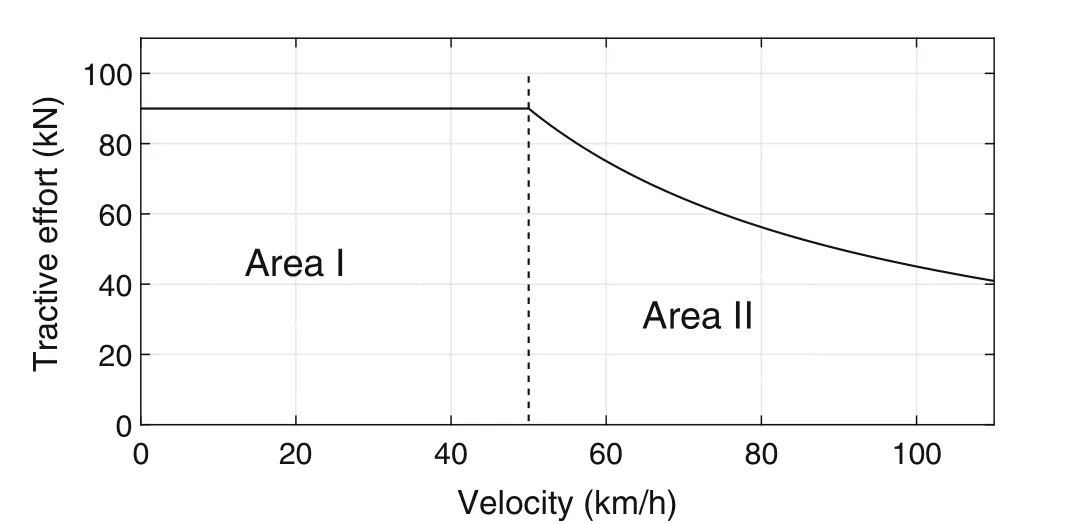
Fig. 1 A generic tractive effort curve
3.3 Battery models
As presented in Sect. 2,electrical battery models provide a balance between simplicity and accuracy needed for transportation application [34, 40]. In this section, two electrical battery models are suggested and validated, and the suitable one is chosen for the speed profile optimization using dynamic programming.
The function presented in Eq. (8) models the battery voltage based on two variables of current and state of charge. We use two electrical battery models that follow the same function for our application:simple battery model and generic battery model. The simple battery model is an electrical model,which consists of a voltage source and an internal resistance. Voltage of the battery in the simple model [40] is modeled using Eq. (9):

where R is the internal resistance and E0is the battery open circuit voltage value, obtained from the battery manufacturer’s data sheet. The simple battery model assumes that the voltage of the battery is constant with respect to the state of charge. We also study the generic battery model,which considers the state of charge as one of the design variables.
The generic model was first introduced for hybrid electric vehicles [45] and later on validated for electric vehicle application [46]. Eqs. (10) and (11) present the discharge and charge voltage of the battery (i.e., Vbat-dischr and Vbat-chr) in the generic battery model, respectively:
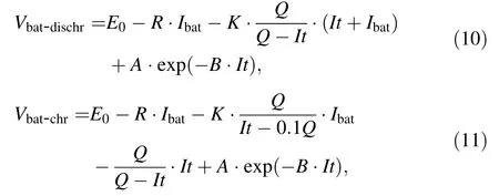
where Q is the battery capacity in Ah, and the coefficients K in V/(Ah), A in V, and B in Ah-1are acquired from the discharge curve provided by the battery supplier [45, 46].
The generic characteristic of these models is one of the main reasons for the wide application of them, since both battery models can be applied to different batteries with different chemistries [34]. Moreover, the design variables of both models can be easily calculated using the manufacturers’ data sheet [46]. The simple battery model has been used before for different applications such as leadacid battery modeling (see, e.g., [47]) and for the application of wind power generation (see, e.g., [48]). The generic battery model has also been used in different applications such as photovoltaic power generation (e.g.,[39]), wind energy generation (e.g., [49]) and DC microgrid (e.g., [50]).
To choose the right model for the speed profile optimization,we need to validate and compare both models for the estimation of the state of charge during operation.
4 Validation and evaluation
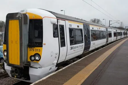
Fig. 2 IPEMU battery-driven train. Image courtesy of Bombardier Transportation goo.gl/KSzRou
4.1 Battery models validation
The validation is done in two parts. We first validate each of the models regarding voltage estimation(Eq. (8)).In the next step, we also validate both models regarding state of charge estimation. For the validations purpose, the coefficient of determination (R-squared) and mean absolute percentage error (MAPE) are used. Equations (12)and (13) present the definition of R-squared and MAPE:

where piis the measured value, ^piis the modeled value, ¯p is the mean of the measured values, and n is the size of the sample.
We use a journey of around 34 km and 2200 s from the IPEMU test runs to validate the voltage estimation using each of the battery models. The models estimate the voltage based on current and state of charge(Eq. (8)).Figure 3 present the current and state of charge profile of the driving cycle used for this validation.
Figure 4 shows a comparison between the measured battery voltage versus the modeled battery voltage using the generic and the simplified battery models. Figure 5 shows the parity plot of the modeled voltage values compared to the measured values on the train and during the catenary-free operation for each of the battery models.
Moreover, Table 2 presents the values of MAPE and Rsquared for voltage estimation using each of the models.
Comparing both battery models using Fig. 5, it can be seen that the simplified battery model is underestimating the voltage value. This is because in the simple battery model, the battery voltage is assumed to be constant with respect to the state of charge. Despite the underestimation,there is still a low deviation of 0·77% in average for the voltage estimation(Table 2).This issue is improved in the generic battery model, as the state of charge is one of the considered variables in this model.
The second part of validation is for the state of charge estimation,using the mass point train model and the battery models. In other words, the state of charge is estimated based on the speed profile. For this purpose, we apply the validated battery models to another driving cycle of around 18 km/h and 1300 s. Figure 6 presents the speed profile of the driving cycle used for the validation of the state of charge estimation.
A visual comparison between the measured and modeled values of state of charge using both models together with the parity plot of the results are presented in Figs. 7 and 8. Values of MAPE and R-squared for state of charge estimation are presented in Table 3.
The results of the state of charge estimation validation show that both battery models can estimate the state of charge with minor error (MAPE in Table 3 and Fig. 7). It is also understood from the value of R-squared and the parity plots in Fig. 8 that both models provide values with minor deviation from the measured values.
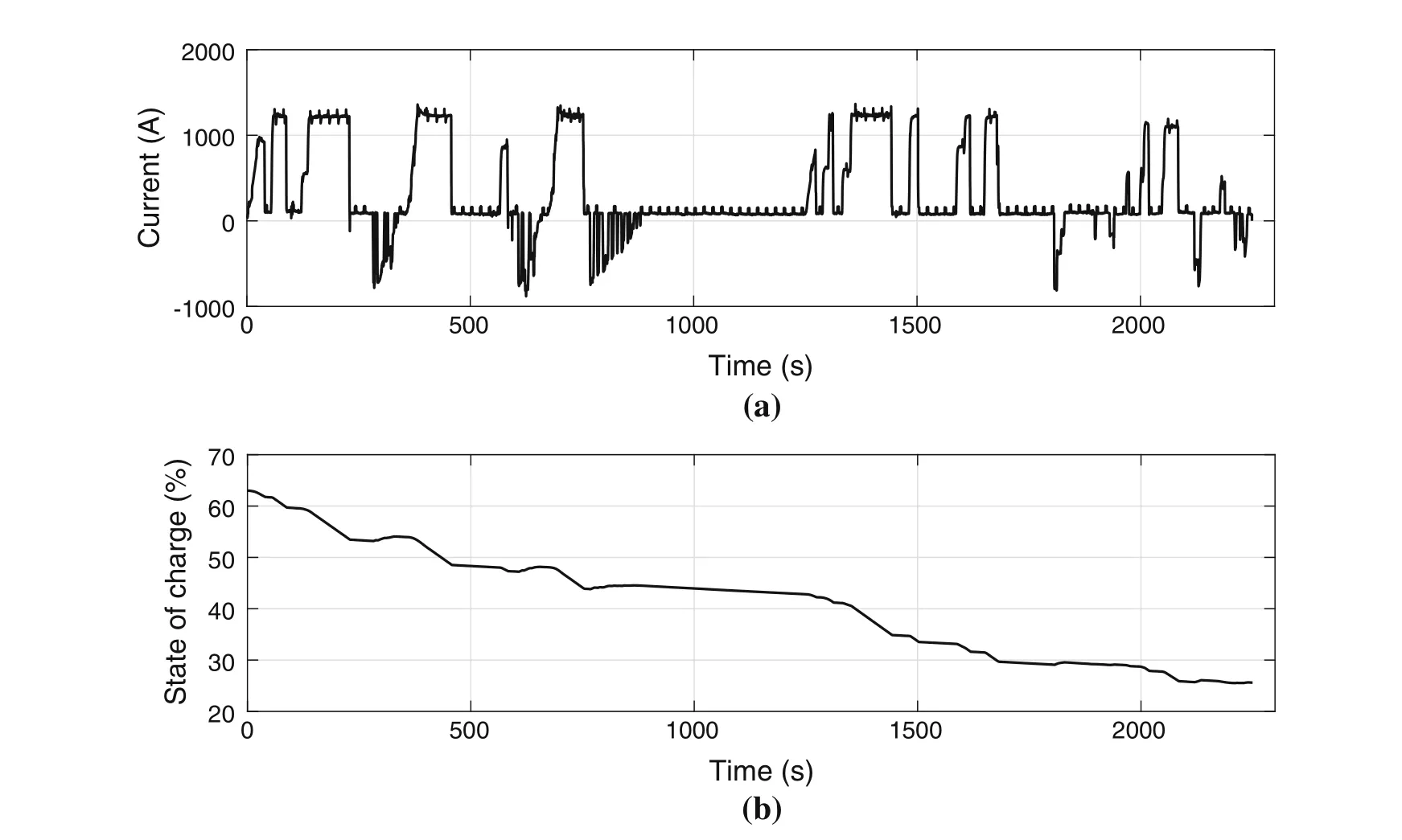
Fig. 3 Current (a) and state of charge (b) profile of the driving cycle used for the voltage estimation validation

Fig. 4 Measured battery voltage compared to the modeled battery voltages using the generic battery model and the simplified battery model
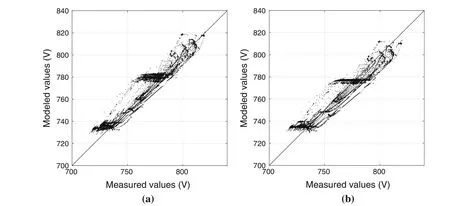
Fig.5 Parity plot of the modeled voltage values compared to the measured voltage values using a generic battery model and b simplified battery model
The validation results in general show that both battery models function with similar accuracy for our application in modeling of the state of charge.Apart from the accuracy,there is also the factor of simplicity of the model.The final goal is to use the battery and train models in a dynamic programming approach to minimize the charge used from the battery.Although DP is known to be suitable for speed profile optimization of trains and battery-driven trains(see,e.g., [27]), it is also well-known that it suffers from the curse of dimensionality [17]. Therefore, it is important to keep the calculations as simple as possible. Moreover,there is a problem of generating the coefficients for the generic battery model (Eqs. (10) and (11)) from the discharge curve. To generate the coefficients, three points from the discharge curve need to be selected [45, 46]. In our experience, the points need to be selected with a high accuracy to have a precise model. In light of this, considering the overall simplicity of the simplified battery modelover the generic model (both the equations and the coefficients), and the similar accuracy of both models in estimating the state of charge, we can conclude that the simplified battery model is suitable for our optimization application.

Table 2 MAPE and R-squared values for voltage estimation
4.2 Experimental evaluation
The battery-driven EMU was tested for a limited number of test runs on a certain line section in UK. We apply the presented dynamic programming approach using the simplified battery model to find the optimum speed profiles for two trips.
The first trip(Trip I)is 3 km from Manningtree station to Mistly station and the second trip(Trip II)is 6·27 km from Mistly station to Wrabness station. Figure 9 presents a comparison between the charge consumption of the experiments versus the charge consumption of the optimum speed profiles.The circled points are the charge taken from the battery during the different test runs of the batterytrain for each of the trips. The solid line represents the optimum charge taken from the battery in different travel times as the result of the optimization on a computer. The results depicted in Fig. 9 show that on average, it is possible to save around 31.6% of the charge on the battery.The solid lines in Fig. 9 are also known as the cost-time curve for the optimal train journey.The cost-time curve for the optimal journey is used as an essential tool for the energy-efficient timetabling of a network of trains[51].As an example, we present a comparison between one of the experiments and the respective optimum driving style in Fig. 10.The trip depicted in Fig. 10 corresponds to a travel in Trip II with the travel time of 330 s and with the initial state of charge of 75%.
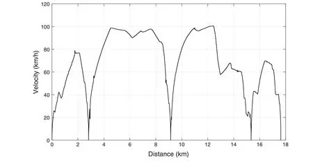
Fig. 6 Speed profile of the driving cycle used for the state of charge estimation validation
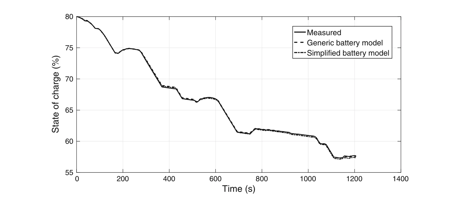
Fig. 7 Measured state of charge compared to the modeled state of charge using the single mass point train model and each of the two battery models
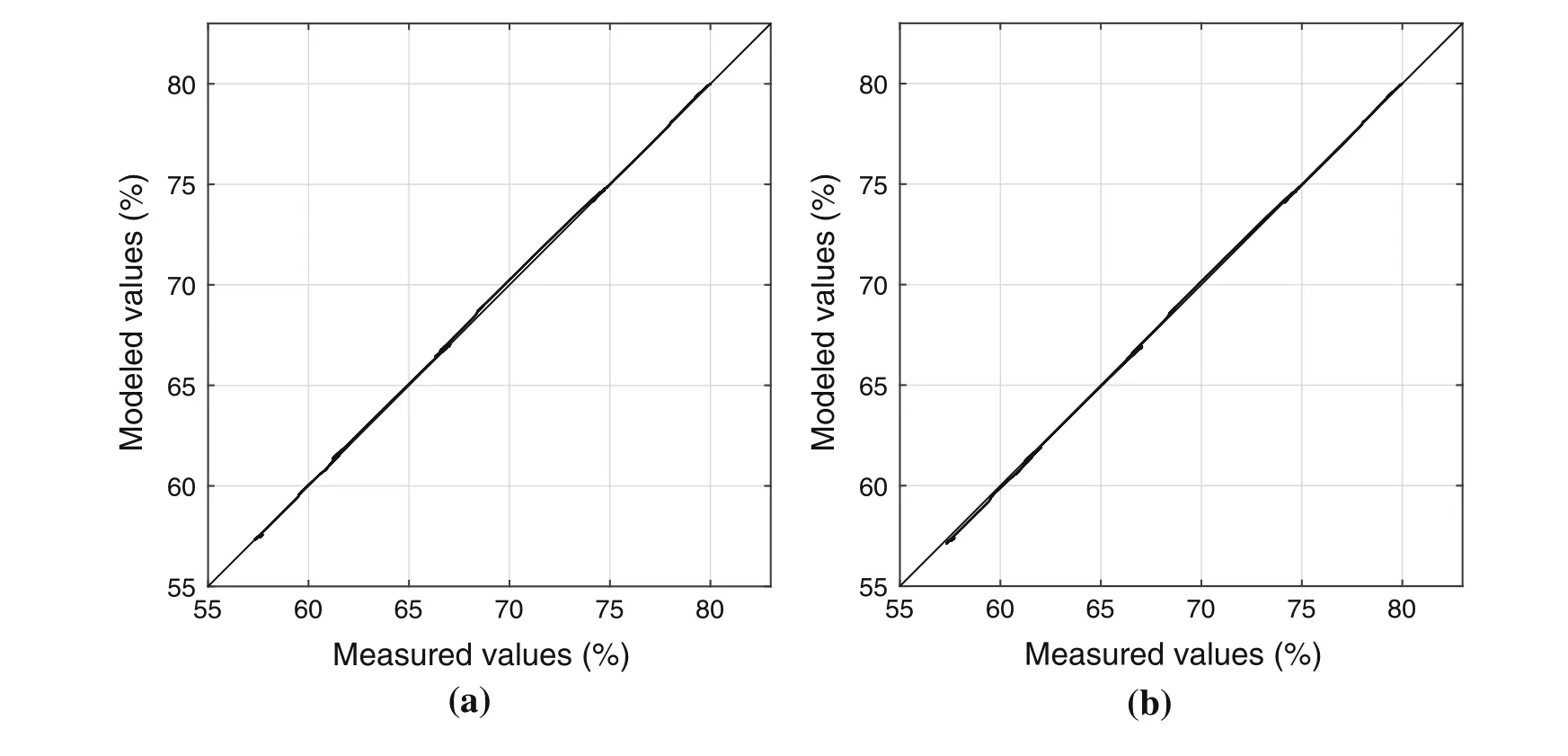
Fig.8 Parity plot of the modeled state of charge values compared to the measured state of charge values using the single mass point train model with a generic battery model and b simplified battery model

Table 3 MAPE and R-squared values for state of charge estimation
5 Discussion
5.1 Battery models validation
The validation is done against the results from two of the longest journeys a battery-driven train has ever done in the catenary-free mode. The journey consists of constant loadphases and multiple charge/discharge phases in which the peak charge and discharge powers were observed.In other words, the full scope of the operation is included in the validation experiments.The validation experiments cover a range of state of charge from 85% to 25%. The performance of the lithium-ion batteries are relatively stable between around 95% and 5% of the state of charge,which is also the recommended operating condition from most of the battery suppliers [44]. Therefore, the validation is acceptable,even though it was done for a specific range of state of charge. This can also be understood from the results of the validation. Both battery models result in a similar accuracy,which shows that in the IPEMU train,the performance of the battery is relatively stable with respect to the changes in state of charge. Moreover, the batteries used for the application of catenary-free operation are sized with the consideration of redundancy for the extreme cases.During the test runs of the IPEMU train for instance, the state of charge below 25% was not observed.
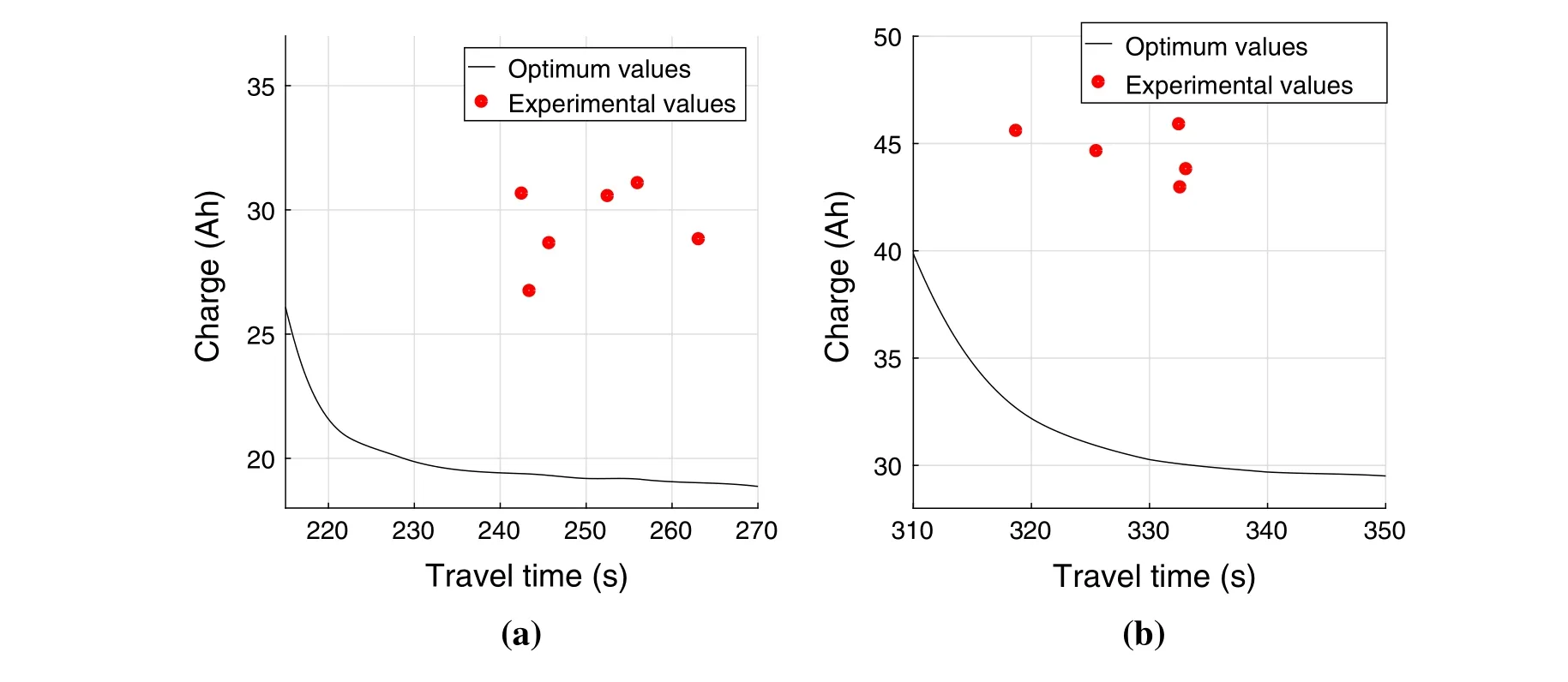
Fig.9 Comparison of the charge taken from the battery between the experiments and the optimization approach a Trip I,3 km from Manningtree to Mistly and b Trip II, 6·27 km from Mistly to Wrabness

Fig. 10 Comparison between an experiment and its respective optimum speed profile in a velocity-distance, b velocity-time and c state of charge-distance plots
The method used in this paper to measure the state of charge is based on the Coulomb counting method, which measures the state of charge according to the integral of the current[52].This method,although accurate,is sensitive to the initial value of the state of charge. The final goal with speed profile optimization in this paper is to implement it in a form of a driver advisory system on-board the train(such as the one presented Ghaviha et al. [17]). There are already battery systems available with battery modules that take advantage of sophisticated electrochemical battery models to monitor the state of charge with high accuracy.Such systems are usually provided by the battery supplier.A driver advisory system based on the approach presented here will be used together with such battery management system on-board the train and will take the initial value of state of charge from it.
Apart from the state of charge and current, two other variables of temperature and state of health can also affect the voltage of a battery [34]. Although the models presented in this paper are sufficient for the speed profile optimization, having a more detailed battery model can lead to a more accurate voltage modeling. For instance, if needed,the behavior seen from time 140 s to 230 s in Fig. 4(or the behavior seen in Fig. 5 around 720 V to 740 V in the measured value) can be modeled with a more detailed battery model.
5.2 Selection of the objective function
We minimize the charge taken from the battery (in Ah)instead of the conventional approach of minimizing the energy consumption (in kWh) in the form of mechanical power. Charge in Ah times voltage is the energyconsumption in kWh. Since the voltage is not constant during operation,measuring of the charge in A h will have a better estimation of the energy taken from the battery and the capacity left.
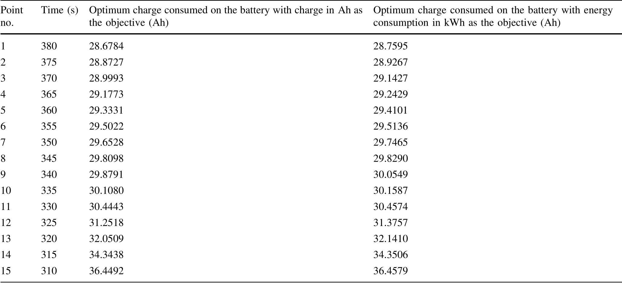
Table 4 Comparison between the optimization using charge minimization as the objective function and power consumption minimization as the objective function
We compare both approaches to study the effects of this change.The final aim is to minimize the charge;therefore,we find the optimum speed profile using both approaches and calculate the charge consumed from the battery for each of the optimum speed profiles. For this purpose, we consider 15 travels between Mistly and Manningtree stations(i.e.,Trip II)with different travel times between 310 s and 380 s. Table 4 presents the minimum charge taken from the battery for each of the points using each of the approaches.
As it can be understood from Table 4,the use of battery charge in the objective function results in the speed profiles that consume on average 0·23% less charge from the battery. It is expected that this value would increase in the batteries with a more unstable voltage (e.g., in case of the batteries with higher internal resistance that results in higher voltage drop). To study this effect, we assume a higher internal resistance to present a battery with a more unstable terminal voltage.For the sake of study,we assume that the internal resistance is doubled.We run the dynamic programming approach with the new value for the resistance and generate the speed profiles using both approaches. The results are presented in Table 5. A comparison between the results from the two approaches considering the higher internal resistance (Table 5) shows that the approach with the minimization of power as the objective function consumes on average 1·05%more charge from the battery.Comparing the results from Tables 4 and 5,we can see that the internal resistance (as one of the main parameters defining the dynamic behavior of the battery)has a strong influence on the results of the speed profile optimization. In addition, we can see that the effects of internal resistance can be more drastic in the batteries with higher voltage fluctuations. Considering the results, we conclude that although the improvement in energy efficiency is low for our case study, the method of using battery charge as the objective function provides in general more efficient speed profiles, especially in the case of energy storage devices with a more unstable terminal voltage.
5.3 Speed profile optimization
As the validation results in Sect. 5 showed, the simple battery model provided enough accuracy for our case. The reason is the fact that in case of the IPEMU train, the battery voltage has minor fluctuations with respect to the state of charge, which can also be understood from the validation results. In case of batteries with a voltage more sensitive to the state of charge,the generic battery model or other similar models can be used instead.
Apart from the accuracy of the model, the voltage drop of the battery will also affect the maximum tractive effort curve.The tractive effort curve used for the simulation and optimization purpose in this study is suitable for a certain range of voltage. In other words, the effects of voltagefluctuations are already considered with the designed tractive effort curve and train configuration. As presented under the train model(Eq. (6)),there is a limitation on the maximum tractive effort available from the traction system, which is typically presented by the tractive effort curve(Fig. 1).In case of a drastic voltage drop and in order to provide a certain tractive effort, the current should be increased drastically.This might not be possible due to the limitation on the maximum current from the motor or energy storage device. Hence, the original maximum tractive effort curve will drop. As an example, the change in the tractive effort curve in different voltages is depicted in Fig. 11.
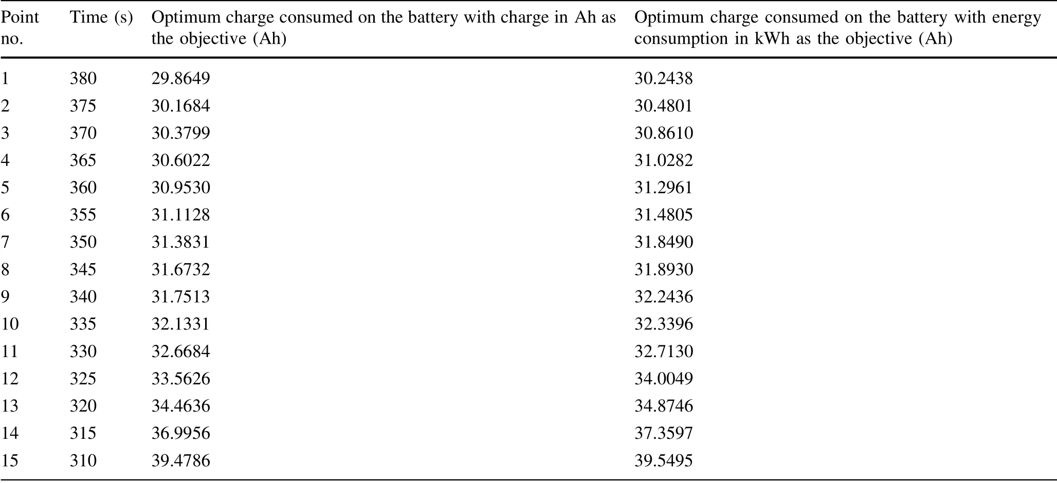
Table 5 Comparison between the optimization using charge minimization as the objective function and power consumption minimization as the objective function with higher internal resistance
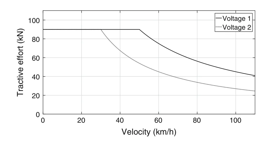
Fig. 11 A generic tractive effort curve in different voltages where V1 >V2
The voltage of the battery used for the IPEMU project,however, is relatively stable with respect to the state of charge.Moreover,the designed motor converter module in the IPEMU train can handle the voltage fluctuations of the designed battery and keep the same tractive effort curve.Therefore,one tractive effort curve is used in this research.Furthermore, dynamic programming is known to be suitable for handling the constraints on state variables [17].In the dynamic programming approach used in this paper,state of charge is assumed as a state variable.Therefore,the constraints related to the state of charge can be handled by this approach (such as the constraint on the battery capacity, i.e., Eq. (5)). This also includes the constraint resulting from different tractive effort curves in different states of charge,which can happen in other battery types or train configurations.
Application of dynamic programming for the speed profile optimization using the methods presented in this paper shows the potential of 31.6% reduction in charge consumption from the battery (Fig. 9). It is important to note that reduction in charge consumption can be less in practice.Such algorithms for the speed profile optimization are usually implemented in a form of a driver advisory system, which gives instructions to the driver (see e.g.,[17]). The drivers, however, may not always follow the instructions(e.g.,due to the lack of trust or difficulty of the provided instructions), which will result in a lower energy efficiency. Moreover, we considered the problem of energy-efficient train operation for a single train. In order to maximize the effectiveness of the solution in practice,the whole network of trains and timetables should be considered. Consideration of the whole network of trains will result in a much more complex optimization problem,which was out of the scope of the work presented in this article.
6 Conclusion and future work
In this paper, we studied the consideration of battery characteristics in the problem of speed profile optimization of battery-driven electric trains during catenary-free operation. This was done by combining the single mass point train model and an electrical battery model. We further applied a dynamic programming approach to minimize the charge taken from the battery and discussed the behavior of the battery in the speed profile optimization using this approach. Moreover, the models and the results are validated and evaluated against the test runs of an actual battery train.
We estimated the state of charge for the speed profile optimization using the single mass point train model and an electrical battery model.We studied two battery models for this purpose: the simple battery model and the generic battery model. We showed that for the case of the IPEMU train, the simple battery model can provide the same accuracy as the generic battery model. However, the generic battery model or other similar battery models (models following the function of Vbat=U(soc,Ibat)) can be used for other similar cases where the behavior of the battery is more dependent on the state of charge.There are catenaryfree light rail vehicles currently in service with EDLCs on board(see e.g.,[1])and there are also reports on catenaryfree EMUs with on-board fuel cell [28]. The verification and the approach presented in this paper were specific for the case of lithium-ion batteries, but both fuel cell and EDLC technologies have the potential of benefiting from the same methodology for speed profile optimization.There are similar models for these type of energy storage devices available in the literature (e.g., the fuel cell model proposed by Njoya et al. [53]). Further studies are, however, needed to verify the applicability of the approach for such technologies.
We used charge taken from the battery as the objective function instead of the energy consumption in kWh. The results of a comparison between the two approaches show that,in general,the application of the battery charge as the objective function provides more energy-efficient speed profiles in comparison with the method with the energy consumption in kWh as the objective. Moreover, the dynamic programming approach used in this paper considers the state of charge as a state variable. Having the state of charge as a state variable facilitates handling different constraints that come from the specific behavior of the batteries in different states of charge. This is particularly important as it provides the opportunity to apply the same optimization approach for the energy storage devices with a behavior more dependent on the state of charge.
The experimental evaluation of our approach using the test runs of an actual battery-driven train shows significant potential in saving energy consumption from the batteries.This concludes that the approach presented here can be used as a basis for designing a driver advisory system for catenary-free operated electric trains. Further research is needed to investigate the barriers and challenges for the implementation of the mathematical solution in the form of a driver advisory system on-board the train.
This paper provided the first experimental evaluation of a speed profile optimization approach for catenary-free operated electric trains.Further studies in this field require more experimentation and test runs with new battery-driven trains with different energy storage technologies.
AcknowledgementsThis research was funded by VINNOVA(Sweden’s Innovation Agency) Grant Numbers 2014-04319 and 2012-01277. Authors would like to thank Martin Joborn from Linko¨ping University for his help, guidance and discussion on the train modeling.
Open AccessThis article is distributed under the terms of the Creative Commons Attribution 4.0 International License (http://creativecommons.org/licenses/by/4.0/), which permits unrestricted use,distribution,and reproduction in any medium,provided you give appropriate credit to the original author(s) and the source, provide a link to the Creative Commons license, and indicate if changes were made.
杂志排行
Railway Engineering Science的其它文章
- Event management architecture for the monitoring and diagnosis of a fleet of trains: a case study
- Statistical delay distribution analysis on high-speed railway trains
- A fault prediction method for catenary of high-speed rails based on meteorological conditions
- Using Kalman filter algorithm for short-term traffic flow prediction in a connected vehicle environment
