Research on energy saving of centralized air-conditioning system based on mathematical model
2019-09-10XueXingWangAnZhuHui
Xue Xing Wang An Zhu Hui


Abstract:Centralized air-conditioning is a multi-component, non-linear, large delay system, all of its air processing equipment are concentrated in the air-conditioning room, it is difficult to model and control the system. At present, there are many researches on energy saving of central air-conditioning system, but most of the studies do not take the whole system as the starting point to establish an effective model. In this paper, the mathematical models of the components of the central air conditioning system are established and simulated, and the influence of the flow rate (air volume) of the refrigerated water, cooling tower and air treatment box on the energy saving effect of the air conditioning system is discussed one by one.
Key words:centralized air conditioning system; mathematical model; flow; energy saving
1 Introduction
With the development of science and technology and the improvement of peopleundefineds living standards, air conditioning has become an irreplaceable part of peopleundefineds work and life. Among them, the equipment of centralized air conditioning system is numerous, the structure is complex, and there are many factors affecting its energy consumption.And the centralized air-conditioning system is composed of various equipment according to certain heat and power characteristics, the components are interdependent, and the characteristics of large hysteresis, multi-variable and random interference are not easy to be controlled[1].
For the above-mentioned characteristics of the central air-conditioning system, how to achieve the energy-saving effect of the whole system by changing the control method of the air-conditioning system has become the key research direction of the experts at home and abroad.Chan KT and others carried out variable flow control of frozen water in central air-conditioning system, and explored the energy-saving potential of variable frozen water flow[2];Jin and so on can improve the energy-saving performance of the system by controlling the water supply temperature of the frozen water and the water supply pressure of the frozen water pump[3]; The model of centrifugal chillers was established by Lee et al[4]. The influence of variable flow rate of frozen water on the operation performance of air conditioning system was studied[5];According to the year-round operation data of the air conditioning system, Wang et al analyzed the influence of the frequency conversion control of the frozen water pump and the cooling pump on the energy saving of the system[6]; Hu Lei and others reformed the air-conditioning chillers and studied the energy-saving effect of variable flow rate of cooling water[7]. The effects of variable flow rate (air volume) on the performance of air-conditioning system are discussed one by one in the research of frozen water pump, cooling pump and air treatment box.
In this paper, the mathematical model of air-conditioning system is established and verified. Based on the established air-conditioning system model, the freezing water pump and cooling tower are studied one by one. The influence of variable flow rate (air volume) of air-conditioning treatment box on the energy-saving effect of the system.
2 Composition and principle of centralized air conditioning system
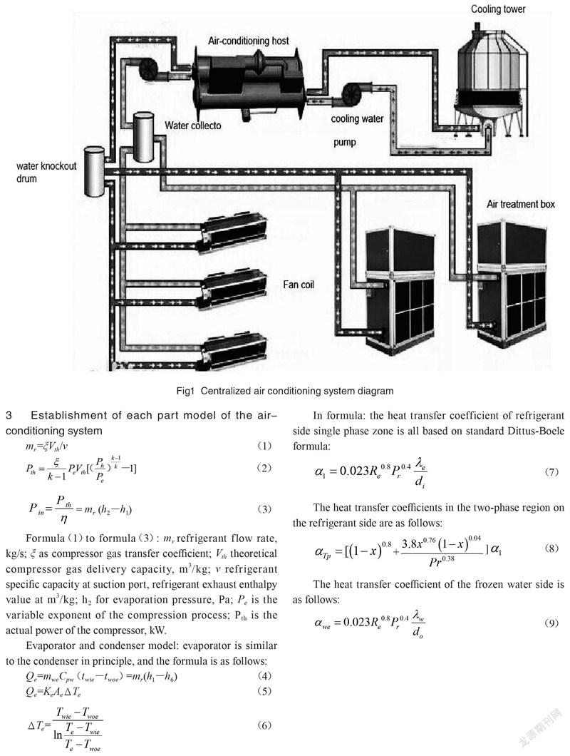
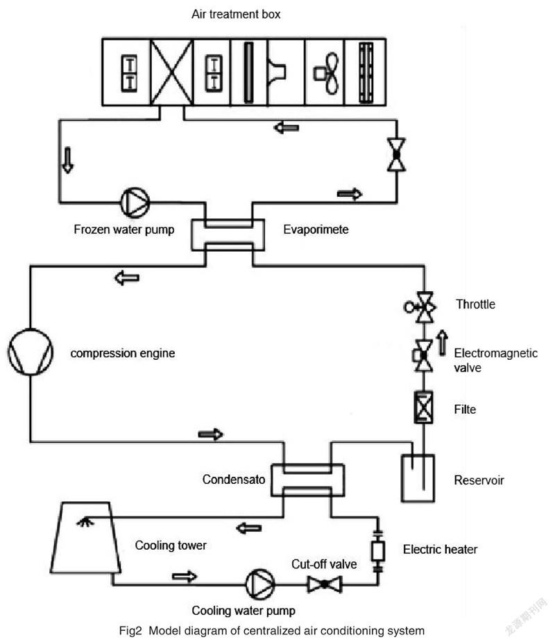
Centralized air conditioning system means that all air treatment equipment is concentrated in air conditioning room, there are water chillers and air treatment equipment, all kinds of terminal systems and so on. The main components of the central air conditioning system are: cooling pump, frozen water pump, chiller, cooling tower, air processor, etc. The central air-conditioning system connects the air outlet through the air duct or hot pipe, and the main engine sends the heating and cooling to different areas to achieve the purpose of regulating the indoor air[8].
3 Establishment of each part model of the air-conditioning system
Formula(1)to formula(3): mr refrigerant flow rate, kg/s; ξ as compressor gas transfer coefficient; Vth theoretical compressor gas delivery capacity, m3/kg; v refrigerant specific capacity at suction port, refrigerant exhaust enthalpy value at m3/kg; h2 for evaporation pressure, Pa; Pe is the variable exponent of the compression process; Pth is the actual power of the compressor, kW.
Evaporator and condenser model: evaporator is similar to the condenser in principle, and the formula is as follows:
In formula: the heat transfer coefficient of refrigerant side single phase zone is all based on standard Dittus-Boele formula:
The heat transfer coefficients in the two-phase region on the refrigerant side are as follows:
The heat transfer coefficient of the frozen water side is as follows:
Formula: mwe for the flow rate of frozen water, kg/s; Cpw is the specific heat capacity of water, and kJ/kg; twie、twoe is the inlet, outlet temperature and ℃ of frozen water, respectively; h6 it is the enthalpy of refrigerant throttling, kJ/kg; Qe is refrigeration capacity, and kW; Ke is the refrigeration capacity. For the total heat transfer coefficient of the evaporator, W/(m2·K); Ae is the evaporator area, m2; ΔTe the average temperature difference in heat transfer, K; λe is the thermal conductivity of the refrigerant, W/(m·K); λw is the thermal conductivity of the water, W/(m·K); do is the external diameter of evaporator tube, m; di is the inner diameter of evaporator tube, m.
Throttle model: refrigerant flow formula is:
In: Cv for flow coefficient; Av for valve flow area, m2; ρv for refrigerant liquid density, kg/m3; Pvi、Pvofor throttle valve inlet and outlet pressure, Pa.
(1)Air treatment box model:
Qcoil is for air treatment box heat exchange, kW; twic, twoc is refrigerated water inlet / outlet air treatment box temperature, mac is air conditioning box air volume, m3/h, hair, haoc are air in and out air treatment box enthalpy, kJ/kg; ε1, ε2 are the coefficient of heat exchange efficiency and contact coefficient, tgi, tgo are the dry bulb temperature of air in and out of the air treatment box, tsi, tso the wet bulb temperature of air in and out of the air treatment box, ℃, NTU is the number of heat transfer units of the air treatment box, respectively, γ is the temperature of the dry bulb of air in and out of the air treatment box. αo is for water equivalent ratio,W/(m2·k); Acoil for air side surface heat transfer coefficient; air side heat transfer area, m2.
Cooling tower model:
mw·t is for the cooling tower water mass flow, kg/s; dz is the vertical length of the cooling tower packing, ma·t is the cooling tower air mass flow rate, kg/s; X is the air vapor mass component in the cooling tower, tw·t is the cooling water temperature is the cooling water temperature, ha·t the cooling water temperature is the cooling water temperature, kJ/kg; A is the cooling water temperature is the cooling water temperature. Fz is the enthalpy of the air in the cooling tower, m2; βt is the saturated air moisture content corresponding to the water temperature, and the moisture content of the saturated air corresponding to the water temperature. W/(m2?℃); Cpv·a for constant pressure specific heat with air temperature as qualitative temperature. kJ/ (kg. ℃); at air temperature as qualitative temperature, kJ/kg; ta·t for water. For air temperature, ℃.
Pump and fan model: pump and the fan follow the similar law:
In this model, V is the flow rate of pump or fan, m2/s; H is head, m; ρ is water or air density is water or air density, kg/m3;P is power, kW; ηVFD is frequency converter, motor efficiency is motor efficiency, pump efficiency is pump efficiency, ηm is frequency converter. Subscript m indicates rated condition.
4 System simulation and results
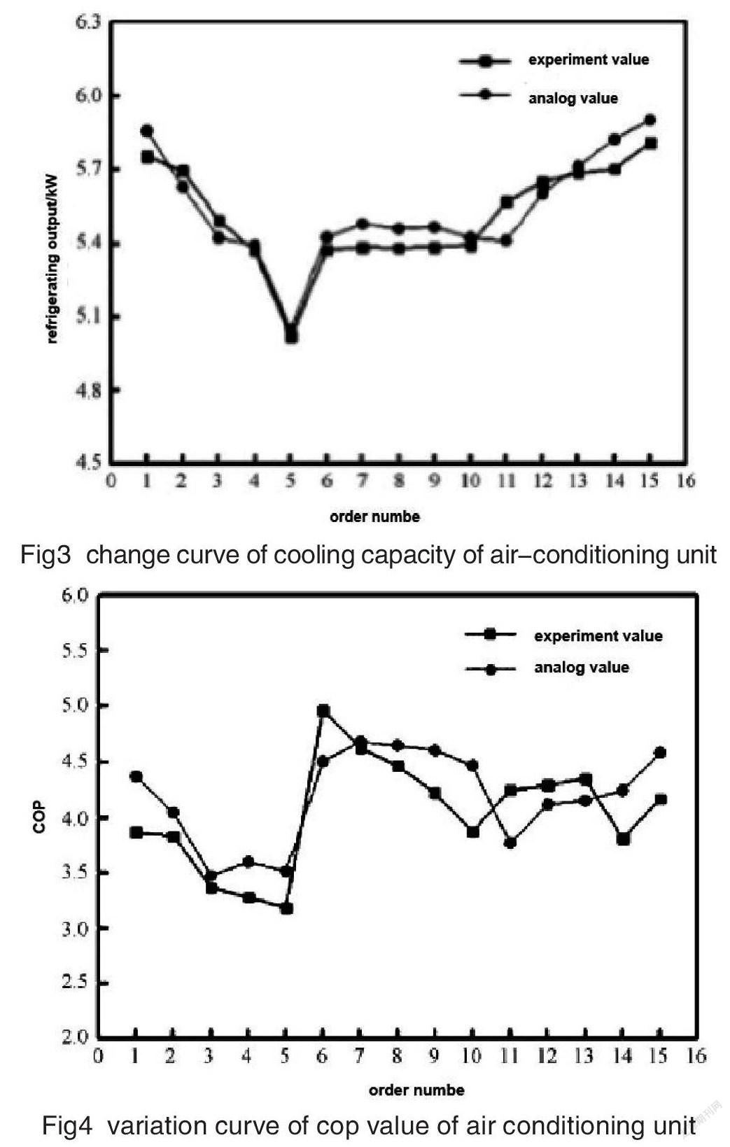
In order to verify the accuracy of the model, the frozen water flow rate(0.5%)was tested in this paper(0.5~0.8 kg/s), cooling water flow rate(0.6~1 kg/s), air treatment box(600~1 200 m3/h)was measured to measure the cooling water, the inlet and outlet temperature of cooling water, the air inlet and outlet status of air treatment box and cooling tower, and the energy consumption of air conditioning units. Water pump energy consumption and fan energy consumption are compared with the predicted results under the same working conditions to verify the accuracy of the model.
When the flow rate of the chilled water pump is changed, the flow rate is set to 50%,62.5%,75%, 87.5% and 100% of the rated flow, respectively. And the flow rate of the cooling water and the air volume of the air treatment box are kept constant; and when the flow rate of the cooling water pump is changed, the flow rate is respectively set to be 63. 6%, 72.7%, 81.8%, 90.9% and 100%. When the air volume of the air treatment box is changed, the air volume is set to 50% of the rated air volume, and 62. 5%,75%,87. 5% and 100%. The flow of chilled water and cooling water is kept constant.
Fig3 is a comparison of the experimental and simulation results of the cooling capacity of the water chilling unit under different working conditions. It can be seen from the figure that the maximum cooling capacity is within 5%. Fig4 shows the comparison between the experimental value of the performance coefficient(COP value)of the unit and the simulation value under different working conditions, and the maximum deviation of the COP value is within 10%, and the accuracy of the system model is verified.
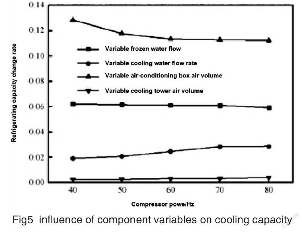
In this paper, the dry bulb temperature of the air conditioning system is set to 26 ℃, the wet bulb temperature is 18 ℃, the inlet dry bulb temperature of the cooling tower is 35 ℃, the wet bulb temperature is 26 ℃, and the flow rate of the frozen pump is 0.8 kg/s. The flow rate of the cooling pump is 1 kg/s, the air volume of the air treatment box is 1 200 m3/h, and the fan flow rate of the cooling tower is 5 200 m3/h, which is set to 100% and 87% of the rated flow, respectively 5%, 75%, 62. 5% and 50%.
Fig5 is the effect of variable cooling water flow rate, variable air treatment box air volume and cooling tower air volume on the cooling capacity of the air conditioning system. The change rate of refrigerating capacity in the diagram is the ratio of the change of refrigerating capacity to the refrigerating capacity at rated flow rate when the above parameters are reduced from 100% to 50%.
5 Summary
As can be seen from figure 5, the cooling capacity of the system is reduced by about 6.5% and 2.3% respectively when the cooling water, the cooling water flow, the air flow rate of the air treatment box and the cooling tower are reduced from 100% to 50% of the rated flow, respectively, and the cooling capacity of the system is reduced by 6.5% and 2.3%, respectively. 11.8% and 0.3%. Because the change of condensation temperature has no direct effect on the heat transfer process of the evaporator and has little effect on the cooling capacity of the air conditioning system, the influence of the variable cooling water flow rate and the variable cooling tower air volume on the cooling capacity is relatively small. On the whole, the air volume of the variable air treatment box has the greatest influence on the cooling capacity, followed by the variable freezing water, the cooling water flow rate, and the variable cooling tower air volume has the least effect on the refrigerating capacity.
[Reference]
[1]YU F W,CHAN K T.Improved energy performance of air cooled centrifugal chillers with variable chilled water flow[J].Energy Conversion&Management,2008,49(6):1595-1611.
[2]JIN X,DU Z,XIAO X.Energy evaluation of optimal control strategies for central VWV chiller systems[J].Applied Thermal Engineering,2007,27(5/6):934-941.
[3]LEE T S,LIAO K Y,LU W C.Evaluation of the suitability of empirically-based models for predicting energy performance of centrifugal water chillers with variable chilled water flou[J].Applied Energy,2011,93(5):583-595.
[4]WANG F J,CHANG T B,CHEN M T.Energy Conservation for Chiller Plants by Implementation of Variable Speed Driven Approach in an Industrial Building[J].Energy Procedia,2014,6(1):2537-2540.
[5]BRADLEY B,SCHWEDLER M.Variable primary flow in chilled-water systems[J].Heating piping air Conditioning,2003,3(75):37-45.
[6]BRANDON F.LACHNER.The use of water as refrigerant:impact of cycle modification on commercial feasibility[D].University of Wisconsin,School of Mechanical Engineering,2004.
[7]SAIDUR R,HASANUZZAMAN M,MAHLIA T M,et al.Chillers energy consumption,energy savings and emission analysis in an institutional buildings[J].Energy,2011,36(8):5233-5238.
[8]MENG QINGLONG,YAN XIUYING,REN QINGCHANG.Global optimal control of variable air volume air-conditioning system with iterative learning:an experimental case study[J].Journal of Zhejiang University-Science a,2015,16(4):302-315.
