An Improved Integration for Trimmed Geometries in Isogeometric Analysis
2019-08-13JinlanXuNingningSunLaixinShuTimonRabczukandGangXu
Jinlan Xu,Ningning Sun,Laixin Shu,Timon Rabczuk and Gang Xu,
Abstract: Trimming techniques are efficient ways to generate complex geometries in Computer-Aided Design (CAD).In this paper,an improved integration for trimmed geometries in isogeometric analysis (IGA) is proposed.The proposed method can improve the accuracy of the approximation and the condition number of the stiffness matrix.In addition,comparing to the traditional approaches,the trimming techniques can reduce the number of the integration elements with much fewer integration points,which improves the computational efficiency significantly.Several examples are illustrated to show the effectiveness of the proposed approach.
Keywords: Isogeometric analysis,trimming curves,trimmed geometry,computational efficiency.
1 Introduction
IGA is an numerical method,combining the computer aided design (CAD) and finite element analysis (FEA) with the same NURBS basis functions.Geometries in CAD are usually represented by splines (B-splines,NURBS,T-splines,PHT-splines for instance),with the geometries in FEA are commonly based on Lagrange polynomials.These two different geometry descriptions introduce inconsistencies in CAD and CAE designs which require reapproximating the CAD geometries in CAE.This does not only introduce errors in the geometry but increase the entire design-to-analysis time.It was demonstrated in Cohen et al.[Cohen,Martin,Kirby et al.(2015);Xu,Mourrain,Duvigneau et al.(2013);Xu,Mourrain,Duvigneau et al.(2011)] that the mesh quality has a big impact on the analysis results,and meshing operation occupies a large percentage in the entire analysis procedure.IGA unifies the geometry representation of design and analysis,by using the same CAD spline functions in CAE simplifying the design-analyze process,and ensuring the exact geometry during the analysis.If a high precision numerical solution is requested,mesh refinement is inevitable.In FEA,posterior error is often used to guide the refinement,and the refinement based on the mesh is sometimes not appropriate,so re-meshing will be needed which have to be interact with original model.In practical engineering analysis,this is a severe bottleneck.IGA applies the same spline basis functions for the geometry generation and the numerical analysis without remeshing procedure.The geometry is represented exactly at the coarse level,which avoid introducing the geometrical errors.Refinement at any level can take place completely within the analysis framework,which eliminates the necessity to communicate with the geometry.
Most of CAD models cannot be represented by a single tensor-product spline surface but several patches of spline surfaces are needed [Xu,Chen and Deng (2015)].However,it is not easy to construct a complex geometry with multiple patches of spline surfaces,especially a certain continuity is required.In such cases,trimming techniques are usually employed.But trimming technology brings gaps and overlaps between surfaces because of inaccuracies along the intersection.Other techniques to approximate the geometry without gaps and overlaps are proposed,including T-splines [Sederberg,Zheng,Bakenov et al.(2003);Brovka,López,Escobar et al.(2014)],PHT-splines [Deng,Chen,Li et al.(2008);Chan,Anitescu and Rabczuk (2017)],THB-splines [Falini,Speh and Jüttler(2015)],and LR B-splines [Johannessen,Kvamsdal and Dokken (2014)] etc.If trimming techniques are used,normal elements and trimmed elements will be considered separately during isogeometric analysis.Kim et al.[Kim,Seo and Youn (2009)] proposed a method to solve this problem.Schmidt et al.[Schmidt,Wüchner and Bletzinger (2012)] proposed a reconstruction method using geometric bases to evaluate the finite element constituents of trimmed elements.This method covers both bases of a single patch and multi-patches.Shen et al.[Shen,Kosinka,Sabin et al.(2014)] introduced a method to convert trimmed NURBS surfaces to subdivision surfaces,and their method can produce gap-free models which are mandatory for numerical analysis.Moreover,the resulting models areG1continuous between two adjacent surfaces.Zhu et al.[Zhu,Hu and Ma (2016)] proposed a spline called B++ spline,to express the trimmed NURBS patch in an analytic form.They solved the problem of implementing essential boundary conditions in isogeometric analysis.The basis functions of B++ spline satisfy the Kronecker delta property which allows imposing essential boundary condition strongly,and this is similar with FEM.Other interesting approaches on isogeometric analysis for trimmed surfaces,can be found in Kang et al.[Kang and Youn (2016);Breitenberger,Bletzinger and Roland (2013);Beer,Marussig,Zechner et al.(2014);Ruess,Schillinger,Özcan et al.(2014);Wang,Benson and Nagy (2015);Zhu,Ma and Hu (2017);Marussig,Zechner,Beer et al.(2016)]and references therein.In this paper,we improve the method proposed by Kim et al.[Kim,Seo and Youn (2010)].
The original method in Kim et al.[Kim,Seo and Youn (2010)] is based on NURBS-enhanced integration.Both surface and trimming curve are represented using NURBS.For the trimming curve,there are two kinds of curve information in IGES files,which are defined in physical and parametric domain respectively.They classified the trimmed elements in parametric domain into three types,which correspond to the following three types in parametric domain:a pentagon with one curved side;a quadrilateral with one curved side;a triangle with one curved side.For the integration of trimmed element,Gauss quadrature points are chosen as integration points.In their method,curved triangles are parameterized by rectangles which make the integration simple.Pentagons are decomposed into three triangles where two of the triangles are normal,the other one is with one curved side.Quadrilaterals are decomposed into two triangles where one is normal triangle and the other one is triangle with one curved side.To summarize,the final integration elements are:(a) triangles with one NURBS curved side,(b) normal triangles.Triangular Gauss integration points are used for normal triangles.But for triangles with one NURBS curved side,they are transformed to a rectangular domain through several mappings,hence Gauss quadratures in quadrilateral are used during integration.
In the method proposed in this paper,the procedure of isogeometric analysis on trimmed geometries is similar,but the integration elements are a little different from the original method.Based on the three types of trimmed elements in parametric domain,the integration elements are classified into (a) triangles with one NURBS curved side,(b)quadrilaterals.The pentagon will be decomposed to two quadrilaterals and the quadrilaterals will not be decomposed into two triangles in our method,therefore the integration elements are less than original methods and integration points will be reduced at the same time which can improve the computational efficiency.
The paper is organized as follows.In Section 2,we summarize the basics of the IGA formulation on trimmed geometries presented in Kim et al.[Kim,Seo and Youn (2010)].In Section 3,we describe our method to deal with trimmed element in details.Section 4 gives several examples of our proposed method,and comparison to the method in Kim et al.[Kim,Seo and Youn (2010)] are also presented.We end this paper with conclusions in Section 5.
2 Preliminaries
NURBS bases are the most common basis functions for representing free-form objects.However,tensor product form of NURBS surfaces makes the representation of complex objects non-trivial.Trimming techniques eliminate this limitation of NURBS.There are many research works of isogeometric analysis for trimmed geometries [Zhu,Ma and Hu(2017);Guo,Ruess and Schillinger (2017);Ruess,Schillinger,Bazilevs et al.(2013);Breitenberger (2016);Marussig,Zechner,Beer et al.(2017)].But the earliest work is proposed by Kim et al.[Kim,Seo and Youn (2009)],which is simple and direct.As our method is based on this work,we will give a brief introduction about the flowchart of this work in this section.
2.1 Flowchart of trimmed isogeometric analysis
Trimming techniques employ NURBS curves to trim unwanted parts of geometries from NURBS surfaces as shown in Fig.1.And trimming technique not only simplifies the construction of complex models,but also keeps the smoothness of the untrimmed parts.If both trimming curves and untrimmed surfaces are NURBS,the resulting trimmed surface is called trimmed NURBS surface.For a trimmed surface,the CAD files contain the surface information in the parametric space and physical space.Fig.1 shows two surfaces in physical space trimmed by shapes of butterfly and sheep.

Figure1:Two examples of trimmed NURBS surfaces
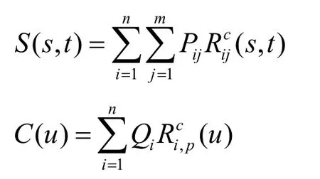
Suppose a trimmed surface is represented by a NURBS surface and a NURBS curve:
If the physical equation defined on trimmed surface is a Poisson equation with Dirichlet boundary condition,

where Ωis the trimmed geometry represented by a NURBS surface and several trimming NURBS curves.
The coefficient matrix of the weak form is given by


Figure2:Three types of elements:(a) type A with one corner trimmed out;(b) type B with two corners trimmed out;(c) type C with three corners trimmed out

Figure3:Segmentation of elements with type A and type B

Figure4:Transformation of curved triangular cell
2.2 Imposition of essential boundary condition
In isogeometric analysis,essential boundary conditions cannot be imposed as in FEM,because NURBS basis functions do not satisfy the Kronecker delta property.For homogeneous essential boundary conditions,the coefficients of basis functions corresponding to boundary are set to zero.The imposition of non-homogeneous essential boundary conditions requires special techniques such as modification of the weak form or the solution of an interpolation problem at the boundary,see e.g.,[Ruess,Schillinger,Özcan et al.(2014)].
In trimmed isogeometric analysis,additional challenges occur for imposing essential boundary condition.The boundary conditions need to be imposed on the trimming curves but the degree of freedom (DOF) is defined on the NURBS surface.Furthermore,there is no mathematical relationship between these two representations.In Kim et al.[Kim,Seo and Youn (2010)],they use Lagrange multiplier method to impose essential boundary conditions on trimming curves.And we use the same method in our algorithm.
The Lagrange multipliersλ(u)are supposed to be expressed as

KU+ATλ=f,AU=b,
where

3 Improved integration on trimmed geometry
The main contribution of our method is to modify the integration rules for the trimmed elements.For type C in Kim et al.[Kim,Seo and Youn (2010)],a similar method is applied to generate integral points on the curved triangle,but for type B [Kim,Seo and Youn (2010)],a mapping from a rectangle to the curved quadrilateral element is used which avoids the triangular decomposition of the curved quadrilateral element.For type A,decomposition is adopted but it is different from the method in Kim et al.[Kim,Seo and Youn (2010)].The curved pentagon is segmented to two quadrilaterals,one with a curved edge and the other is rectangular.
Fig.5 shows the decomposition of type A in our method.The segmentation of trimmed elements of type A can be chosen on the basis of the intersection points.SupposePaandPbare two intersection points,wherePbis closer to the corner point which is trimmed out,then the trimmed element is segmented at pointPa.
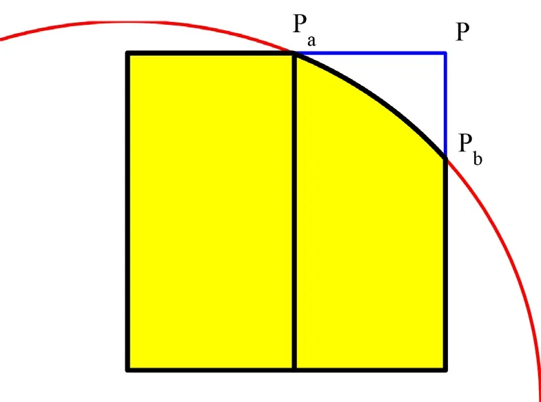
Figure5:The trimmed element of type A is decomposed to two quadrilaterals


Figure6:Trimmed element of type B.There are four cases for the curved quadrilaterals according to which two consecutive corners are trimmed out
Except trimmed elements of type C,all trimmed elements are represented as quadrilaterals.For the curved quadrilateral which contains one curved edge as part of trimming curves,the mapping from unit rectangle is constructed as follows:according to the location of the curved edge,there are four types of curved quadrilaterals as shown in Fig.6.Supposeare parameters of the trimming curve at the intersections.For each case,the mappingQbetween the curved quadrilateral and rectangle can be described as follows.
(a):Ifu1is the parameter of the left intersection point,the mappingQis constructed as

otherwise,

(b):Ifu1is the parameter of the right intersection point,the mappingQis constructed as

otherwise,

(c):Ifu1is the parameter of the bottom intersection point,the mappingQis constructed as

otherwise,

(d):Ifu1is the parameter of the top intersection point,the mappingQis constructed as


otherwise,Gauss quadrature is commonly used in isogeometric FE approaches.Compared to the method proposed by Kim et al.[Kim,Seo and Youn (2010)],the proposed method leads to less integration points.Fig.7 shows the distribution of Gauss points in our approach compared to the approach in Kim et al.[Kim,Seo and Youn (2010)] for one trimmed element.In Fig.7,it can be seen that Trimmed element of type A is decomposed into three triangles in Kim et al.[Kim,Seo and Youn (2010)],where one of triangle with a curved edge.Gauss points are selected for each triangle.But in our method,element of type A is decomposed into two quadrilaterals,and the number of Gauss points for each quadrilateral is the same with curved triangle.For element of type B,no decomposition is carried out in our method,since then the number of Gauss points is less than the method in Kim et al.[Kim,Seo and Youn (2010)].In fact,the reduction of integral points can be estimated.SupposenGauss points are chosen for the normal triangle,andmGauss points are chosen for the curved triangle.As the number of integral points for quadrilateral element is the same with curved triangle,we can give the number of integral points for each type of trimmed element,see Tab.1.
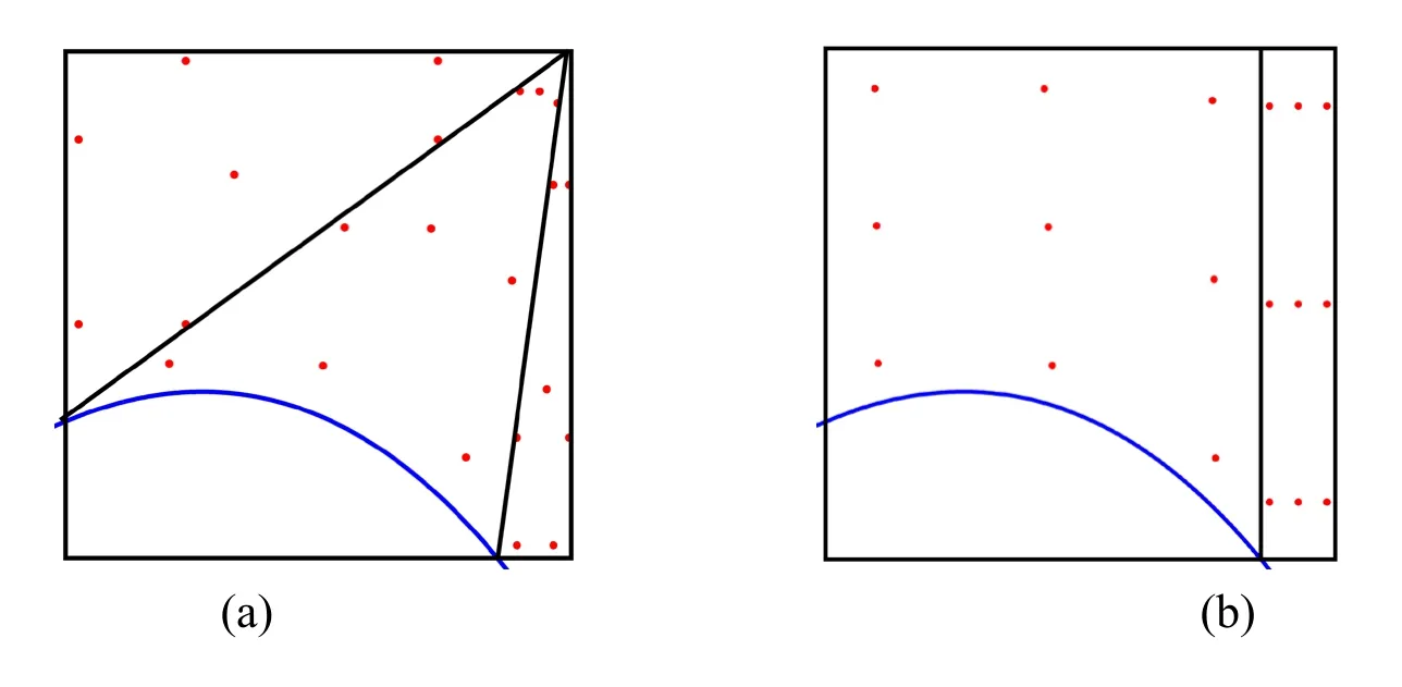
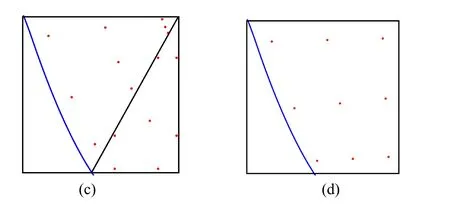
Figure7:Integration points and segmentation of trimmed elements.(a)(c) type A and type B elements in Kim et al.[Kim,Seo and Youn (2010)],(b)(d) type A and type B elements in our method

Table1:Comparison of the number of integral points
4 Numerical examples
In this section,we solve the Poisson equation on several trimmed geometries to show the effectiveness of our method,and compare our results with results obtained by the method in Kim et al.[Kim,Seo and Youn (2010)].
For the method in Kim et al.[Kim,Seo and Youn (2010)],basis functions are NURBS basis functions.Three Gaussian points are used in each direction for quadrilateral element,and seven Gaussian points are used for the regular triangle.
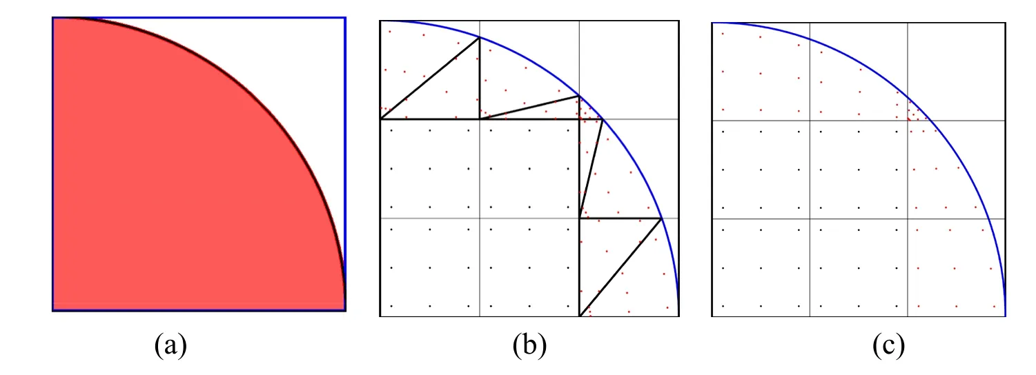
Figure8:Integration points and segmentation of trimmed elements with3× 3elements:(a) computational domain of EX1;(b) integration points in Kim et al.[Kim,Seo and Youn (2010)];(c) integration points in the proposed method
In the first example,the exact solution isx2+y2-1.We choose a very simple geometry,the computational domain is fan-shaped.It is constructed by trimming a corner of a rectangle using an arc represented by a NURBS curve with degree two.In this example,we compare the correspondingL2error of numerical solution,and the condition number of stiffness matrix with the method in Kim et al.[Kim,Seo and Youn (2010)] as shown in Tab.2.We also compare the computational cost of Ex1 as presented in Tab.3,whereTerepresents the trimmed element andrepresents the integration element after the decomposition ofTe.

Table2:Comparison of our method with the proposed method in Kim et al.[Kim,Seo and Youn (2010)] for Ex1
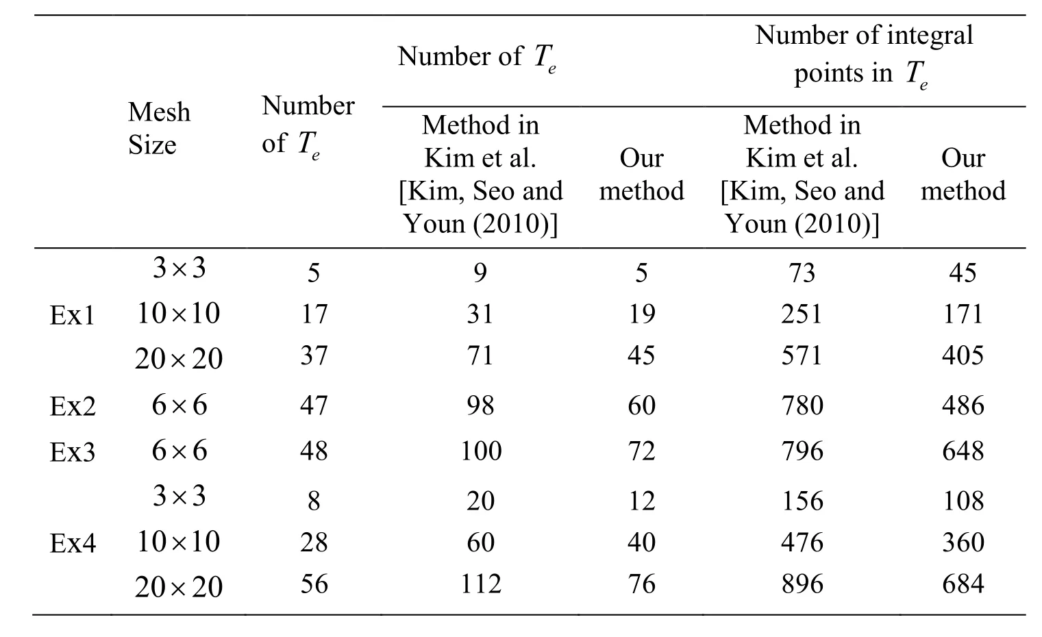
Table3:Comparison of computational cost with the Method in Kim et al.[Kim,Seo and Youn (2010)]

Figure9:Comparison of numerical solution with 20 × 20grid.(a) the method in Kim et al.[Kim,Seo and Youn (2010)];(b) our method;(c) exact solution;(d)L2error of method in Kim et al.[Kim,Seo and Youn (2010)];(e)L2error of our proposed method
We use the method presented in Kim et al.[Kim,Seo and Youn (2009)] to find all the active elements,and construct the mapping from the unit square [0,1]×[0,1]to each trimmed element as described in Section 3.When the spline surface consists of 3× 3elements,with our method,the distribution of the integration points on the computational domain is more regular than the method in Kim et al.[Kim,Seo and Youn(2010)] as illustrated in Fig.8.The corresponding numerical solution andL2error are shown in Fig.9.From Tab.2,we can see that the condition number of the stiffness matrix and theL2error of the numerical solution is reduced almost by one half compared to the method in Kim et al.[Kim,Seo and Youn (2010)] on the refined grid.
In the second example,exact solution isx(1 -x)y(1 -y).We construct a computational domain with a little more complex geometry,where the rectangle is trimmed by a closed spline curve.There are two protrusions in the interior of the final trimmed geometry.In this example,the surface contains6 × 6elements first.However,there are other kind of trimmed elements except of three types we processed in this coarse mesh,so local refinement is performed on the surface as described in Kim et al.[Kim,Seo and Youn(2009)] until there are only three types of trimmed elements.In this example,there are many trimmed elements of type B,as shown in Fig.12.The element of type B is decomposed into two triangles with the method in Kim et al.[Kim,Seo and Youn(2010)],integration on this element then becomes integration on these two triangles.In the proposed method,we construct a mapping from type B element to rectangle directly while keeping the number of integral elements.Our method can reduce a half integral points and integral elements for this type of trimmed element.For type A,one third of integral points and integral elements can be reduced by our method.
In the third example,we also choose the exact solutionx(1 -x)y(1 -y).A round hole is trimmed out from a rectangle as computational domain.The number of trimmed elements of type A and type C are more than type B,in this case the reduction of integral points and integral elements is not as significant as the first example.It can be clearly observed from Tab.2.And in this example,the number of trimmed elements of type A becomes more and more during mesh refinement process,and the reduction of integral elements is clearly demonstrated.
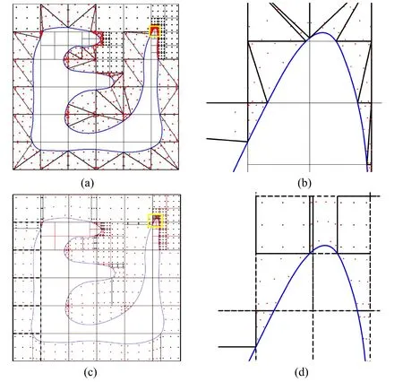
Figure10:The computational domain of EX2.(a) elements and integral points of the method in Kim et al.[Kim,Seo and Youn(2010)];(b) enlarge the area of yellow rectangle in (a);(c) elements and integral points of our method;(d) enlarge the area of yellow rectangle in (c)

Figure11:The computational domain of EX3:(a) elements and integral points of the method in Kim et al.[Kim,Seo and Youn (2010)];(b) enlarge the area of yellow rectangle in (a);(c) elements and integral points of our method;(d) enlarge the area of yellow rectangle in (c);(e) numerical solution;(f)L2error is 4.43065× 10⁻⁴
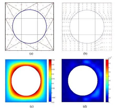
Figure12:The computational domain of EX3.(a) elements and integral points of the method in Kim et al.[Kim,Seo and Youn (2010)];(b) elements and integral points of our method;(c) numerical solution of 10× 10grid;(d)L2error is 3.26665× 10⁻⁴
5 Conclusion
In this paper,we propose an improved integration of isogeometric analysis over trimmed geometries on two-dimensional planar computational domain.By the proposed method,the integral elements and integral points in analysis process can be reduced significantly,which improves the efficiency of analysis.Moreover,compared with the previous method,the distribution of integral points is more regular,and the accuracy of numerical solution is also improved.Several numerical examples are given to show the effectiveness of the proposed approach.
In the future,we will consider more efficient integration method,and the improvement of integration on curved triangular element.Extension to three-dimensional isogeometric analysis is also a part of our future work.
Acknowledgement:This research was supported by the National Nature Science Foundation of China under Grant Nos.61602138,61772163,61761136010,61472111,Zhejiang Provincial Natural Science Foundation of China under Grant Nos.LQ16F020005,LR16F020003,and Zhejiang Provincial Science and Technology Program in China (2018C01030).
杂志排行
Computers Materials&Continua的其它文章
- A Capacity Improving Scheme in Multi-RSUs Deployed V2I
- A Multi-Objective Decision-Making Approach for the Optimal Location of Electric Vehicle Charging Facilities
- Multi-Rate Polling:Improve the Performance of Energy Harvesting Backscatter Wireless Networks
- A Novel Scene Text Recognition Method Based on Deep Learning
- Fuzzy C-Means Algorithm Automatically Determining Optimal Number of Clusters
- Ab Initio Molecular-Dynamics Simulation Liquid and Amorphous Al94-x Ni6 Lax (x=3-9) Alloys
