Polarized red,green,and blue light emitting diodes fabricated with identical device configuration using rubbed PEDOT:PSS as alignment layer∗
2019-08-06HaoranZhang张皓然QiZhang张琪QianZhang张茜HuizhiSun孙汇智GangHai海港JingTong仝静HaowenXu徐浩文andRuidongXia夏瑞东
Haoran Zhang(张皓然), Qi Zhang(张琪),‡, Qian Zhang(张茜), Huizhi Sun(孙汇智), Gang Hai(海港),Jing Tong(仝静), Haowen Xu(徐浩文), and Ruidong Xia(夏瑞东)
Key Laboratory for Organic Electronics&Information Displays(KLOEID),Jiangsu-Singapore Joint Research Center for Organic/Bio Electronics&
Information Displays,Institute of Advanced Materials(IAM),Nanjing University of Posts and Telecommunications,Nanjing 210046,China
Keywords: organic semiconductors,light-emitting devices,polymer liquid crystals,display devices
1. Introduction
Organic semiconductors attract considerable attention due to their unique merits in chemical structure tunability,solution processability, and mechanical flexibility.[1]The organic optoelectronic devices are widely developed and intensely studied in the fields of light emitting diodes,[2,3]solar cells,[4,5]field effect transistors,[6,7]and plastic lasers.[8-10]Among the applications, organic light emitting diodes(OLEDs)were firstly exploited and possess the most promising future. Due to the strong demand from the consumer market and continuous efforts devoted by the manufacturers,OLEDs technology has been regarded as the solution for the next generation display of smartphones, laptops, and televisions. In recent years, polarized emission from liquid crystal materials has drawn growing interests from both academic and industrial circles because of the potential in optoelectronic applications, including backlight sources for conventional liquid crystal displays (LCDs),[11]three-dimensional imaging,[12]and so on. Unlike the traditional method of combining a polarizer with an unpolarized light source for achieving light polarization,OLEDs with aligned active layer can directly produce polarized emission,[13-15]which avoids waste of the ~50% production light. The emission dichroic ratio,D=I‖/I⊥,is the ratio of intensity of the parallel and perpendicular linearly polarized electroluminescence(EL)emissions.The degree of alignment in the active layer is of paramount importance to give a high dichroic ratio (also known as polarized ratio) of the polarized emission from resulting light emitting diodes (LEDs). During the past two decades,[15,16]various methods for emitting layer alignment have been developed,such as mechanically stretched on films,[13,17,18]mechanical friction with cloth or teflon rod,[19-21]the Langmuir-Blodgett (LB) deposition technique,[22-24]and self-assembly of organic liquid-crystals.[25,26]Among them, the mechanical friction method is a relatively simple and efficient way to produce an aligned organic emissive layer. Through such a method, with the help of a rubbed alignment layer, typically the polyimide (PI),[27]one can manipulate the orientation of the molecule in the active layer easily. Whereas,to integrate the aligned active layer in the OLEDs, the insulated PI layer has to be modified by blending in a conductive compound[28]or replaced with an alternative hole transport layer such as poly(p-phenylenevinylene) (PPV)[28,29]or poly(3,4-ethylene dioxythiophene): poly(styrene sulphonate)(PEDOT:PSS).[30,31]Unfortunately, PPV itself is an emissive polymer with strong absorption in the visible range. It will be tricky for device fabrication to avoid the reabsorption of initial emission and subsequent re-radiation caused by the PPV. To serve the purpose,PEDOT:PSS layer seems more adaptable to work as both hole transport and alignment layer.
In this work, polyfluorene, poly (9,9-dioctylfluorene)(PFO) and its derivatives, poly (9,9-dioctylfluorene-cobenzothiadiazole) (F8BT) and poly (triphenylamine-co-4,7-di(thiophen-2-yl)benzo[c][1,2,5] thiadiazole-co-benzo[c]thiadiazole-co-9,9-dioctyl-9H-fluorene) (Red F) are used as the active materials for polarized LEDs. The non-liquidcrystallinity behavior polymer, Red F,can also achieve a certain degree of anisotropy through physical mixing with F8BT and benefit from the energy transferring in the meantime. The PFO/F8BT (5 wt.% F8BT) shows similar dichroic ratio in absorption/emission and results performance-enhanced LEDs,comparing to F8BT itself. The red, green, blue (RGB) light emitting diodes using the same rubbed alignment PEDOT:PSS layer are realized with identical device configuration. Reasonable dichroic ratio value is achieved in all polarized LEDs with simple device fabrication.
2. Results and discussion
The polymers used in this work are commercially available compounds, polyfluorene and its derivatives, namely,PFO, F8BT, and Red F (chemical structures shown in Fig. 1(b), details given in the experimental section). The isotropic absorption and photoluminescence (PL) spectra of these polymers on quartz are show in Fig.S1 of the supporting information. It is worth noting that the absorption of F8BT(Red F) has good overlap with the emission of PFO (F8BT),implying efficient energy transfer from PFO (F8BT)[32]to F8BT(Red F).[33]It is well known that PFO and F8BT exhibit liquid crystallinity. This feature allows them to achieve monodomain alignment with the help of a mechanically rubbed layer such as PI.[28]These polymers have so called“hairy rod”molecular architecture which includes a stiff backbone with flexible side chains. However, Red F is different from PFO or F8BT (Fig. 1(b)), and unable to realize chain orientation through self-assembly. Therefore,in this work,F8BT is used as the host for Red F,providing both energy transfer and chain orientation. The polarized absorption and PL spectra of the aligned polymer films in Fig.1(a)reveal the pronounced optical anisotropy of all samples.The absorption/PL dichroic ratio(Dabs/DPL) can be calculated by dividing the peak intensity parallel to the alignment direction to that perpendicular to the alignment direction in the spectra. The Dabs/DPLcalculated from Fig. 1(a) are 3.2 (at 390 nm)/2.8 (at 432 nm) for PFO,6.8(at 464 nm)/6.7(at 542 nm)for F8BT,6.5(at 390 nm)/6.4(at 533 nm)for PFO/F8BT blend,and 2.3(at 472 nm)/1.9(at 625 nm)for F8BT/Red F blend.Although there is only 5 wt.%F8BT in the PFO/F8BT blend, the Dabs/DPLof the resulting blend film is on the same level of that of F8BT itself,indicating efficient energy transfer in the aligned PFO/F8BT blend polymer film.
Some early reports[34,35]claimed that the possible damage to the PEDOT:PSS layer during the rubbing procedure will affect the performance of the resulting polarized LEDs. Nevertheless, the atomic force microscopy (AFM) image of the rubbed PEDOT:PSS layer(on ITO glass)shows a root-meansquare(RMS)roughness of 0.78 nm with no evidential thread of scratching (see Fig. S2 in supporting information). The morphology of the aligned polymer films(thickness ~70 nm)deposited on top of the PEDOT:PSS layer is also considerable uniform for all polymers(RMS roughness ~1.21 nm for PFO,0.86 nm for F8BT,~1.22 nm for PFO/F8BT,and 1.61 nm for F8BT/Red F) and shows no phase separation in the blends,which will facilitate the device fabrication.

Fig.1. (a)Polarized absorption and photoluminescence spectra of the polymers and the blends. Solid line||: polarizer parallel to rubbing direction,dashed line⊥: polarizer perpendicular to rubbing direction. (b)Chemical structures of the polymers.
To understand if the rubbed PEDOT:PSS layer in our work (protocol in experimental section) can fully align the polymers on top, the dependence of the absorption dichroic ratio on film thickness is investigated(see Fig.S3 in supporting information). The maximum thicknesses of the polymer films that can be fully aligned are 92 nm for PFO, 112 nm for F8BT,73 nm for PFO/F8BT,and 166 nm for F8BT/Red F blend. These values all exceed the thickness of active layers used in the LEDs fabrication hereinafter.
The LED configuration involved in this work is presented in Fig. 2(a). An extensively applied standard structure, indium tin oxide (ITO, 120 nm)/PEDOT:PSS (30 nm)/polymer(70 nm)/LiF (1 nm)/Al (120 nm), is used without further optimizing for specific active material. The rubbed PEDOT:PSS layer is employed directly as both hole injection and alignment layer. Another set of control samples using the same materials and device configuration are also fabricated without mechanical friction treatment on the PEDOT:PSS layer. In Fig. 2(b), the EL spectra of the polarized LEDs using PFO,F8BT, PFO/F8BT, and F8BT/Red F as the active materials show apparent dichroism (measured at 100 mA·cm-2). The EL dichroic ratios calculated from the emission peaks in the spectra are 3.0,6.7,6.2,and 2.0 for the PFO(432 nm),F8BT(536 nm), PFO/F8BT (544 nm), and F8BT/Red F (636 nm)based devices, respectively. In the following detailed discussion on the performance of the polarized LEDs, the measured maximum luminance intensity and luminance current efficiency parallel/perpendicular to the rubbing direction are labelled as I‖/I⊥and LE‖/LE⊥for each device. In all tests,the lower intensity measurements in perpendicular direction are carried out prior to those in parallel direction to avoid the influence of device degradation on the anisotropy analysis in EL emission. With proper encapsulation, the dichroic ratios of these devices are inferred to be even higher. The current density-brightness-voltage(J-L-V)characteristics of the devices with polarized analysis are displayed in Fig.3 and Table 1. The light turn-on voltages (at a detectable brightness of 2 cd·m-2) are 6.7 V, 3.7 V, 4.5 V, and 4.5 V for the PFO,F8BT,PFO/F8BT,and F8BT/Red F blend polarized devices. The higher light turn-on voltage of PFO-based devices can be assigned to the larger mismatch in the lowest unoccupied molecular orbital(LUMO)level of PFO(about-2.9 eV)with the work function of LiF (about -3.6 eV) compared to F8BT (about -3.5 eV). These values show the same trend with those obtained from the control devices without alignment treatment(depicted in Fig.S4 and Table S1 of supporting information). In fact,the maximum I‖(Fig.3 and Table 1)in the polarized LEDs is also on the similar level of the maximum luminance intensity measured in regular non-aligned devices(Fig. S4 and Table S1). These comparisons indicate no sign of evidential degradation of the polarized LEDs performance resulting from the rubbed PEDOT:PSS layer or thermal treatment.The maximum polarized luminance intensities I‖and I⊥of the PFO device are 2600 cd·m-2and 971 cd·m-2,giving a luminance dichroic ratio I‖/I⊥of 2.7. Similarly,for the F8BT,PFO/F8BT, F8BT/Red F devices, the luminance dichroic ratios are calculated to be 6.2 (8428 cd·m-2/1359 cd·m-2),6.4 (12835 cd·m-2/2002 cd·m-2), and 2.0 (5861 cd·m-2/2904 cd·m-2), respectively. We note that the maximum luminance of PFO/F8BT based LED is 50%higher than that of F8BT based device. This can be ascribed to the higher quantum yield of fluorescence resulted from energy transfer.

Fig. 2. (a) LED configuration: ITO (120 nm)/PEDOT:PSS (rubbed,30 nm)/polymer (aligned 70 nm)/LiF (1 nm)/Al (120 nm). (b) Polarized EL spectra of the polymers and blends. Filled and open symbols represent polarizer detection parallel and perpendicular to the rubbing direction (squares for PFO, down-triangles for F8BT, up-triangles for PFO/F8BT,and circles for F8BT/Red F).
Correspondingly,the polarized maximum luminance current efficiencies LE‖and LE⊥of each device as a function of current density are plotted in Fig. 4. The calculated LE dichroic ratios (DLE) are 2.7 (1.0 cd·A-1/0.38 cd·A-1), 6.2(2.1 cd·A-1/0.34 cd·A-1), 9.5 (3.42 cd·A-1/0.36 cd·A-1),and 1.9 (1.56 cd·A-1/0.82 cd·A-1) in the PFO, F8BT,PFO/F8BT, and F8BT/Red F devices, respectively. Larger maximum luminance and LE of the PFO/F8BT blend based device compared to those of F8BT eventually lead to higher DIand DLE, this is due to better EL performance resulting from energy transfer. These data are summarized together in Table 1.

Fig.3. The current density-brightness-voltage(J-L-V)characteristics of the polarized LEDs with different active layer. Open square: current density. Filled and open up-triangle: luminance collected with polarizer parallel and perpendicular to the rubbing direction.
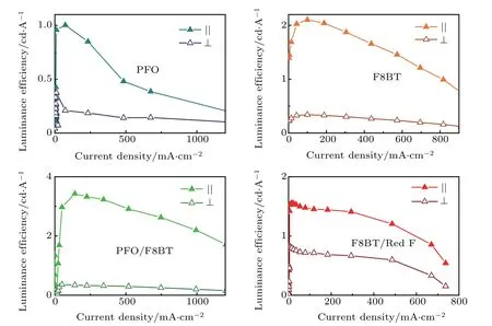
Fig. 4. Luminance efficiency versus current density for polarized LEDs with different active layers. Filled and open up-triangle: luminance current efficiency collected with polarizer parallel and perpendicular to the rubbing direction.

Table 1. Key parameters of the polarized devices. Dabs/DEL is the dichroic ratio of the peak intensity in the absorption/electroluminescence spectra measured in parallel and perpendicular directions. Turn-on voltage is the measured voltage at a detectable brightness of 2·cd m-2. I‖and I⊥represent the maximum luminance intensities measured by a lumen meter in parallel and perpendicular directions. DI is the dichroic ratio of the maximum luminance intensity. LE‖ and LE⊥represent the maximum luminance current efficiencies measured in parallel and perpendicular directions. DLE is the dichroic ratio of the maximum luminance current efficiency.
Reasonable dichroic ratios are achieved in all the samples, confirming that the rubbed PEDOT:PSS hole transport layer enables built-in polarized RGB light emission from simply-constructed LEDs with polyfluorene and its derivatives. In contrast, for regular devices, polarized emission can be achieved only by coupling the output light with an additional polarizer in the price of losing more than half of the brightness and luminance efficiency due to extra scattering and reflection loss (see Figs. S4 and S5 in supporting information).Obviously,using the built-in polarized LEDs demonstrated above is a more efficient and inexpensive solution for the next generation OLED displays or illumination under certain circumstances.
3. Materials and methods
3.1. Materials and solutions
PEDOT:PSS(BAYTRON®P VP CH 8000 or 4083)was purchased from Xi’an Polymer Light Technology Corp. The PFO(Mw=55000)and F8BT(Mw=55000)were purchased from Hanfeng Ltd and Red F from Dow Chemical Company.Solutions of PFO,F8BT,and Red F were made up in toluene(20 mg/mL).By mixing the precursor solutions, we prepared the 5%wt.%F8BT containing PFO/F8BT blend and 10 wt.%Red F containing F8BT/Red F blend solutions.
3.2. Film alignment
The ITO glass or polished synthetic quartz substrates were ultrasonically cleaned by detergent,deionized water,acetone, and ethanol. After drying, they were treated by plasma(PLASMA-PREENII-862) at the power of 70 W for 4 min to remove residual organic impurities on the surface and to improve the hydrophilic properties of the top surface. A PEDOT:PSS alignment layer (30 nm thick) was deposited following by annealing at 120°C for 20 min. After cooled down to room temperature, alignment treatment was carried out by surface rubbing with a home-made machine which contains an electromotor driven drum covering with a velvet cloth.
The conjugated polymer films were then spin-coated onto rubbed PEDOT:PSS from the pre-stirred solution. The adjustment of the film thickness was achieved by changing the spin-coating speed.To achieve chain orientation,the PFO film was annealed at 200°C for 2 min in nitrogen atmosphere,then cooled down to 170°C at a speed of 1°C/min and quenched to room temperature. F8BT,PFO/F8BT blend,and F8BT/Red F blend films were annealed at 265°C for 2 min in nitrogen atmosphere, then cooled down to 235°C at 1°C /min and quenched to room temperature. The hot plate used for annealing treatment was a LINKAM LTS420E-PB4 probe hot stage.
3.3. Morphology measurements
Film morphology tests were carried out at room temperature using a Bruker Dimension Icon AFM equipped with Scanasyst-Air peak force tapping mode atomic force microscope(AFM)tips from Bruker.
3.4. Optical characterization
The absorption and photoluminescence spectra of the samples were measured at room temperature using Lambda 35 UV/VIS spectrophotometer and PerkinElmer LS55 fluorescence spectrophotometer. In absorption measurements, a polarizer(Thorlabs)was placed in front of the incident light slit for generating polarized light parallel or perpendicular to the direction of the oriented polymer chain. In PL measurements,the same polarizer was placed in front of the light collecting slit to couple the polarized emission from the sample.
3.5. LED device fabrication and characterization
Rubbed PEDOT:PSS layer was fabricated on the ITO glass as described above followed by active layer deposition. The thickness of the emission layer was controlled to be 70 nm by changing the speed of spin coating(PFO@4000 rpm,F8BT@4500 rpm,PFO/F8BT@4000 rpm,F8BT/Red F@5500 rpm). Thermal annealing was then employed following the protocol described above to orient the polymer chain. Samples with well-aligned emissive layers were then transferred into a thermal evaporator. 1 nm LiF and 120 nm Al were evaporated onto the polymer in sequence under high vacuum(10-5bar). The device structure is shown in Fig. 2. The EL spectra were measured by a PR-745 spectra scan spectroradiometer. The device brightness was measured by a Keithley 2450 source meter and a PR-745 SpectraScan spectroradiometer. A polarizer (Thorlabs) was used for coupling out the emission light in both polarized and control samples.
4. Conclusion and perspectives
The red, green, blue polarized LEDs are fabricated successfully with the same device configuration using a rubbed PEDOT:PSS layer as both the alignment and hole transport layer. For the non-liquid-crystal polymer compound Red F,through blending with F8BT,the resulting device shows clear dichroism. All polymer layers used in the LEDs can be fully aligned through the identical simple treatment. The performance of the resulting LEDs is not affected by the rubbing or thermal treatment, comparing to the control devices without aligned active layers. The EL dichroic ratios of the LEDs constructed in this work are 3.0, 6.7, 6.2, and 2.0 for the PFO,F8BT, PFO/F8BT, and F8BT/Red F blend-based devices, respectively. Efficient energy transfer in the PFO/F8BT blend results better LED performance with higher maximum luminance and LE, comparing to those of F8BT itself. The RGB built-in polarized LEDs demonstrated in this work can possibly be further integrated together on the same piece of substrate acting as the polarized-emitting pixel in future display plane or illumination source.
Acknowledgment
We acknowledge the valuable discussion with Miss Chen Sun from IMDEA nanoscience(Spain).
猜你喜欢
杂志排行

Chinese Physics B的其它文章
- Coercivity mechanisms in nanostructured permanent magnets∗
- Progress in recycling of Nd-Fe-B sintered magnet wastes∗
- Grain boundary restructuring and La/Ce/Y application in Nd-Fe-B magnets∗
- Topology of triple-point metals∗
- Local evolutions of nodal points in two-dimensional systems with chiral symmetry∗
- Structural,elastic,and electronic properties of topological semimetal WC-type MX family by first-principles calculation∗