Hardware Circuit Implementation and Performance Analysis of Three-Slot NP-CSMA
2019-06-12XuLuHongweiDingZejunHanZhijunYangLiqingWangandLiyongBao
Xu Lu,Hongwei Ding, ,Zejun Han,Zhijun Yang,Liqing Wang and Liyong Bao
Abstract: The development of wireless communication technology has become increasingly important in the communications industry.How to allocate limited channel resources reasonably and reliably to each competing user is a problem that the access protocol of the MAC(Multiple Access Control)layer needs to solve.As an important way of random access,NP-CSMA(Non Persistent Carrier Sense Multiple Access)has a higher network throughput rate when the arrival rate is higher.This paper analyzes and improves the implemented NP-CSMA model,and obtains a three-slot NP-CSMA model.The mathematical tool MATLAB is used to analyze the network throughput,delay and energy efficiency of the model,and compare several random multiple access protocols adheres to the network throughput,they are NP-CSMA,Three-slot NP-CSMA,1-persistent CSMA,P-persistent CSMA,and concludes that the three-slot NP-CSMA is significantly letter than several other multiple access protocols.Finally,using Quartus to design the three-slot NP-CSMA circuit,the statistical value of the circuit system is compared with the theoretical value of the model,and the error is less than 0.01,which proves that the system is reasonable in design and can be applied to wireless communication networks.
Keywords: Three-slot NP-CSMA,FPGA,delay,throughput rate,energy consumption.
1 Introduction
At present,wireless sensor networks have been successfully applied to many research fields including military,natural environment monitoring,industrial production monitoring,medical care and other daily life of human beings[Sun(2015)].The sensor node is responsible for sensing the environmental information in the network,collecting the monitoring data and reporting it to the user node through the aggregation node.Wireless sensor network nodes need to share common channel resources.Random multiple access is an important access method for network nodes.Carrier sense multiple access CSMA is a protocol that uses a competitive method to determine channel usage rights.The protocol only applies to networks that are logically part of the bus topology[Jian,Liu,Wei et al.(2017)].In the network of the bus,each station can independently determine the transmission of the frame.If two or more stations simultaneously transmit the frame,a collision will occur,resulting in an error in the transmitted frame[Ashrafi,Feng and Roy(2017)].The idea of CSMA technology is that the transmitting station first monitors the channel before transmitting the data.If no other station transmits data,the station transmits the data.If there are other stations transmitting data,they will be retired according to a certain strategy.The commonly used back-off strategies are persistent carrier sense multi-access and non-persistent type[Buratti and Verdone(2016)].In the case of a high arrival rate,the non-persistent throughput rate is higher than the adherence type throughput rate.Based on the analysis of the NP-CSMA model,a three-slot NP-CSMA circuit system is designed and several important performances are analyzed.It is concluded that the performance of the improved multiple access system is significantly better than that of NP-CSMA.1-persistent CSMA,P-persistent CSMA several random multiple access protocols[Chen,Wong,Motani et al.(2013);Chowdhury,Ashrafuzzaman and Kwak(2014);Jin,Seo and Sung(2014)].
Multiple wireless users access the channel.If there is no control protocol to queue the data input by each user,a large number of data collisions will occur,resulting in a very low throughput of the system.The access system model is shown in Fig.1 and Fig.2 below[Buratti and Verdone(2013):P-CSMA:a priority-based CSMA protocol for multi-hop linear wireles(2013);Wei,Bianchi,Cheng et al.(2015)].The article realizes the three-slot NP-CSMA multiple access protocol through FPGA design,realizes the reasonable queuing of the data input channel before the data access channel,and increases the throughput rate of the system.

Figure 1:Multi-user access model without control protocol

Figure 2:Multi-user access model with added control protocol
2 Model analysis
2.1 NP-CSMA model analysis
Principle of NP-CSMA:Before the data frame is sent,the station needs to detect the channel.If the channel is detected to be idle,the data frame is sent.Otherwise,if the channel is busy,it will wait for a period of time before sending[Lee and Cho(2018);Guerroumi,Pathan and Derhab(2017)].

Figure 3:NP-CSMA protocol model
In Fig.3,U,B,and I respectively represent three states of successful data frame transmission,data frame collision,and channel idle.TP indicates a transmission time when a packet is successfully transmitted or a collision occurs.BU indicates a joint event in which the packet is successfully transmitted and a collision occurs,indicating that the channel is busy,and Tn indicates a cycle in which the busy period and the idle period occur[Doost,Naderi and Chowdhury(2016);Sarode and Bakal(2017)].
Before analyzing the NP-CSMA model,make the following assumptions and definitions for the model[Atmaca,Şayli,Yuan et al.(2017);Kai,Zhang and Wang(2018)]:
(1)It is assumed that the channel has no noise interference and is ideal;
(2)The mode of channel access is NP-CSMA protocol,and the information packet arrival process on the channel satisfies the Poisson distribution with independent parameter λ;
(3)The length of the time slot in which the channel is idle is a,and the length of the time slot when the packet is transmitted is unit length 1(1 is an integral multiple of a);
(5)E(U)represents the average length required for the information packet to be successfully transmitted,E(BU)represents the average length required for the information packet to be successfully transmitted or collided,and E(I)represents the average length of the idle period;
(6)P(BU)represents the probability of consecutive occurrences of j BU events in a busy cycle;P(I)represents the probability of consecutive occurrences of idle events in one cycle;P(BU,I)represents one cycle of consecutive,the joint probability of the idle event and the j busy events;the number of packets successfully transmitted in the joint event of the BU is k;S represents the throughput rate.
The probability that a time slot is idle is:

The probability that no information packet arrives within a transmission time slot TP is:

The probability distribution of consecutive i idle time slots during an idle period is:

The probability distribution of consecutive j BU in a busy cycle is:

The joint probability of an(I,BU)event occurring within a cycle is:

Average length of the idle period E(I):

Average length of busy period E(BU):

The condition that a packet of information is successfully transmitted is that no packet arrives within the previous transmission slot delay and only one packet needs to be transmitted in this slot.Then the average length of the information packet successfully sent is:


2.2 Three-slot NP-CSMA model analysis
The principle of three-slot NP-CSMA:The station needs to detect the channel before sending the data frame,and if it hears that the channel is idle,it sends the data frame;Otherwise,if the channel is busy,it will wait for a period of time before sending.

Figure 4:Three-slot NP-CSMA protocol model
In Fig.4,U,B,and I respectively represent three states of data frame,it is that success transmission,collision occurrence,and channel idleness.BU indicates a joint event in which the information packet is successfully transmitted and a collision occurs,indicating that the channel is in a busy state.
On the basis of Section 1.1,the following assumptions and definitions are made for the system:
(1)The length of the time slot in which the channel is idle is a,the length of the time slot in which the information packet collides isl,and the length of the time slot when the information packet is successfully transmitted is unit length 1(1 is an integer multiple of a);
According to the formulas(1),(2),(3),(4),(5)in Section 1.1,there are:
The average number of idle periods I is:

The average number of composite events BU is:

The average number of successful events U is:

The average number of collision events B is:

The average length of the idle period I is:

The average length of the success event U is:

The average length of the collision event B is:


3 Implementation of three-slot NP-CSMA based on FPGA
3.1 The overall architecture of the system
Fig.5 above shows the circuit diagram of the three-slot NP-CSMA protocol based on FPGA(Field-Programmable Gate Array).Firstly,the design of the information source input module is performed.The module generates the poisson data stream through the software MATLAB,and inputs the poisson data stream into the Quartus for access.Secondly,the state classification module classifies the input initial data;then the slot length control module pairs Data of different states are allocated for time slots of different lengths;next,the channel monitoring control module monitors by setting a monitoring channel,and implements a random back-off strategy by generating a pseudo-random series;finally,the data receiving statistics module classifies and counts the received data.Comparing the statistical value with the theoretical value to determine whether the design of the hardware circuit is successful[Xu,Ding,Yang et al.(2018);Sun and Dai(2016);Cao,Chen,Cheng et al.(2015)].

Figure 5:overall architecture of the system
3.2 Data source input module
The data source input module is also the source generating module.In order to obtain a valid possion data stream,first using MATLAB to generate a possion data stream,and then convert it into a data source that can be read by Quartus,using random access in Quartus.The memory(RAM)accesses the possion data[Uddin,Rosenberg,Zhuang et al.(2014)].The circuit design in Quartus is shown in Fig.6 below:

Figure 6:Data source input module diagram in Quartus
3.3 Channel state classification module
When multiple users compete for one channel at a time,it is necessary to classify the channels in order to facilitate subsequent processing of the collision data.When no user sends data,the channel is in an idle state,denoted by I;when only one user sends data,the data can be successfully sent,denoted by U;when two or more users send data,the data collides,this is indicated by B.In the FPGA circuit design,the possion data stream sent by the initial station is mapped by eight bits(for example,0000_0001 indicates that the channel is idle;0000_0110 indicates that the channel successfully transmits data;0000_0111 indicates data collision),thereby realizing the state classification of the channel.
3.4 Time slot length control module
The three-slot NP-CSMA needs to normalize the slot length.The length of the idle slot is equal to the length of the transmission delay,which is defined as a,and the length of the successfully transmitted slot is 1,which is just a free slot10 times.In this paper,when using FPGA to implement three-slot NP-CSMA,the length of the collision time slot is set to 0.5,which is exactly five times that of the idle time slot.In the FPGA,the asynchronous FIFO(First Input First Output)and the read/write control module are used to realize the control of the time slot length.The read/write control module is implemented by Verilog,and the data outputted by the FIFO is monitored and analyzed,and then fed back to the read enable end of the asynchronous FIFO.The asynchronous FIFO performs read control based on the feedback data,so that different channel states occupy different time slot lengths[Casares-Giner and Martínez-Bauset(2017);Zhang,Yi,Wang et al.(2011)].The logic block diagram of the time slot length control module is shown in Fig.7 below:
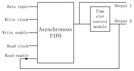
Figure 7:Schematic diagram of the slot length control module
3.5.Channel monitoring control module
In order to monitor channel status and reasonable access of the site in real time,the site is divided into a transmitting site and a monitoring site.The monitoring site transmits only a small amount of data in actual applications,mainly monitoring the state of the channel,and the amount of data sent by the transmitting site.When the channel monitoring station detects that the channel is busy,the three-slot NP-CSMA adopts a control strategy of randomly retreating for a period of time and then monitoring,and the FPGA realizes the function of random back-off by generating a pseudo-random series[Sarkar,Misra,Bandyopadhyay et al.(2015);Chan,Berger and Tong(2013);Bae,Choi and Alfa(2014)].This module implements the multiple access strategy of three-slot NP-CSMA.
3.6 Data receiving statistics module
The module mainly implements statistics on the received data,and the number of timeslots occupied by the station is successfully transmitted,and the throughput rate of the system is obtained by calculating the ratio of the number of occupied slots and the total time slot.This module consists of counters used to count the number of successful time slots for data transmission on the channel[Xu,Ding,Yang et al.(2018)].

In formula(18),t is the total duration of simulation,NUis the number of successful time slots for data transmission in circuit simulation,andTUis the length of time slot in the busy state of the channel,this time slot length is an information packet sent in the algorithm protocol,the theoretical value is 1+a,and the success time slot length is 1,so the length of the calculation success state should be multiplied by.
4 System performance analysis
4.1 Time delay analysis
The paper analyzes the time delay of the three-slot NP-CSMA under the condition that the propagation delay of the information is a,Edrepresents the average length of the delay,andSdrepresents the ratio of the delay to the total time slot length[Lee,Jae-Hyoung,Cho et al.(2017)].The average time delay and the proportion of time delay to total time are:

The time delay of the three-slot NP-CSMA is simulated by MATLAB,and the result shown in Fig.8 is obtained as follows.
Analysis of Fig.8 above shows that the delay of the three-slot NP-CSMA increases with the increase of the reaching rate.In the actual network,because there is too much data to be transmitted,and the channel resources are limited,the delay is also increasing due to the waiting for sending data or the collision of transmitted data.At the same time,we can find that the ratio of the delay to the total time slot length increases with the increase of the reach rate,but when the arrival rate is greater than 70,the ratio tends to 20%.It is indicated that because the arrival rate is increasing,the monitoring function of the control strategy plays a role,so that the delay steadily approaches a certain value.
The ratio of the time extension of the three-slot NP-CSMA to the total time slot length is simulated by MATLAB under different collision time slots,the result shown in Fig.9 is obtained as shown below:
It is not difficult to find in the above Fig.9.Firstly,under the condition of different collision time slot lengths,the change trend of the proportion of the delay is the same as the increase of the arrival rate;secondly,under the same arrival rate condition,the larger the value of the collision slot length l,the smaller the proportion of the delay.
4.2 Energy efficiency analysis
In this paper,when analyzing the energy efficiency of the protocol,the wireless channel energy model proposed in the reference[Ashrafi,Feng,Roy et al.(2015);El-Hoiydi(2002);Nirmala and Nallusamy(2012)]is used.The energy consumption considers the transmission energy consumption,the reception energy consumption and the sensing energy consumption.
Based on the battery model of the paper[El-Hoiydi(2002);Liu,Li,He et al.(2018)],it is assumed that the power isPTXwhen each node is in the transmission state,PRXwhen in the receiving state,andPlmin the channel detection state.
The battery leakage power is 10%,the total energy isE(Wh),and the total energy leaked is 0.1E.The energy consumed is:

When the average power of the sensor node is P,then the life time of the node when the battery energy is exhausted is[Ashrafi,Feng,Roy et al.(2015);Dai and Sun(2013)]:

The average power of the three-slot NP-CSMA control protocol is:

For a LR6 battery,the voltage peaks are 1.5 V and 0.9 V,the average voltage is U=1.2 V,and the capacity is 2.6 Ah.If the battery life is T,the total energy of the battery is:

To simplify the calculation,assume the transmission power:PTX=1.8(mW).Power when receiving state:PRX=9(mW).Power in channel detection state:Plm=0.5(mW).Then the life cycle of the three-slot NP-CSMA control protocol is:

Using MATLAB to simulate the life cycle of three-slot NP-CSMA at different arrival rates,the results shown in Fig.10 are obtained.
Analysis Fig.10 is easy:with the increase of the arrival rate,the life cycle of the node is decreasing,but when the arrival rate of the node increases to 40,the life cycle of the node tends to a certain value,this is because the arrival rate is increasing,and the monitoring function of the control strategy plays a role,so that the life cycle of the node steadily approaches a certain value.
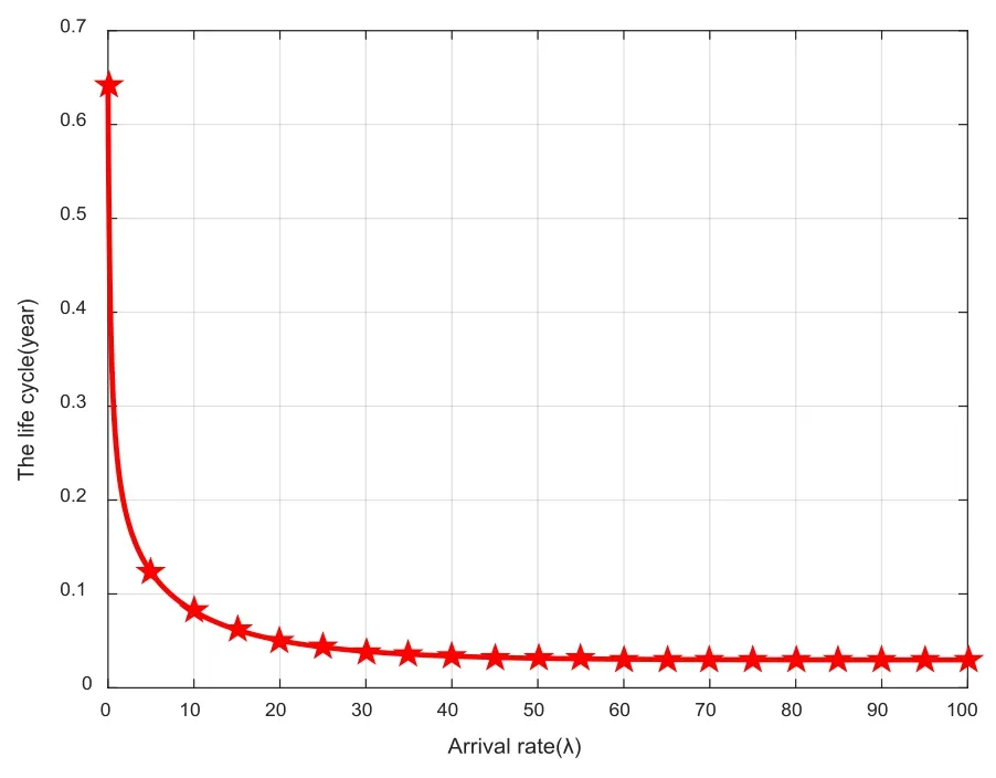
Figure 10:Node life cycle at different arrival rates
Using MATLAB to simulate the life cycle of three-slot NP-CSMA under different collision time slots,the results shown in Fig.11 are obtained.
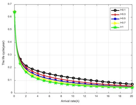
Figure 11:Node life cycle under different collision time slots
Analysis of Fig.11 above is not difficult to find:first,under different collision time slot length conditions,the life cycle change trend of the nodes is the same with the increase of the arrival rate;secondly,under the same arrival rate condition,the value of the collision time slot length l is larger,and the shorter the life cycle of a node.
4.3 Throughput analysis
4.3.1 Simulation Analysis of MATALAB
When the length of the idle time slot a is 0.1,the length of the collision time slotlis 0.5,and the length of the successful time slot is 1.Using MATLAB to simulate the system throughput of NP-CSMA,three-slot NP-CSMA,1-persistent CSMA,and P-persistent CSMA multiple access protocols at different arrival rates[Zhou,Ding,Yang et al.(2017);Tadayon,Wang and Chen(2014)],the results shown in Fig.12 below are obtained.
According to the above Fig.12,it can be obtained that in the case of a small arrival rate,the system throughput rate of the CSMA is increased faster,but the arrival rate only increases to 1 and begins to decrease;the three-slot NP-CSMA system throughput rate is accompanied by the arrival rate.The increase increases until the system throughput rate reaches a maximum at 5 and then begins to decrease.The throughput of the three-slot NP-CSMA is significantly larger than that of several other multiple access protocols after the arrival rate is greater than three.
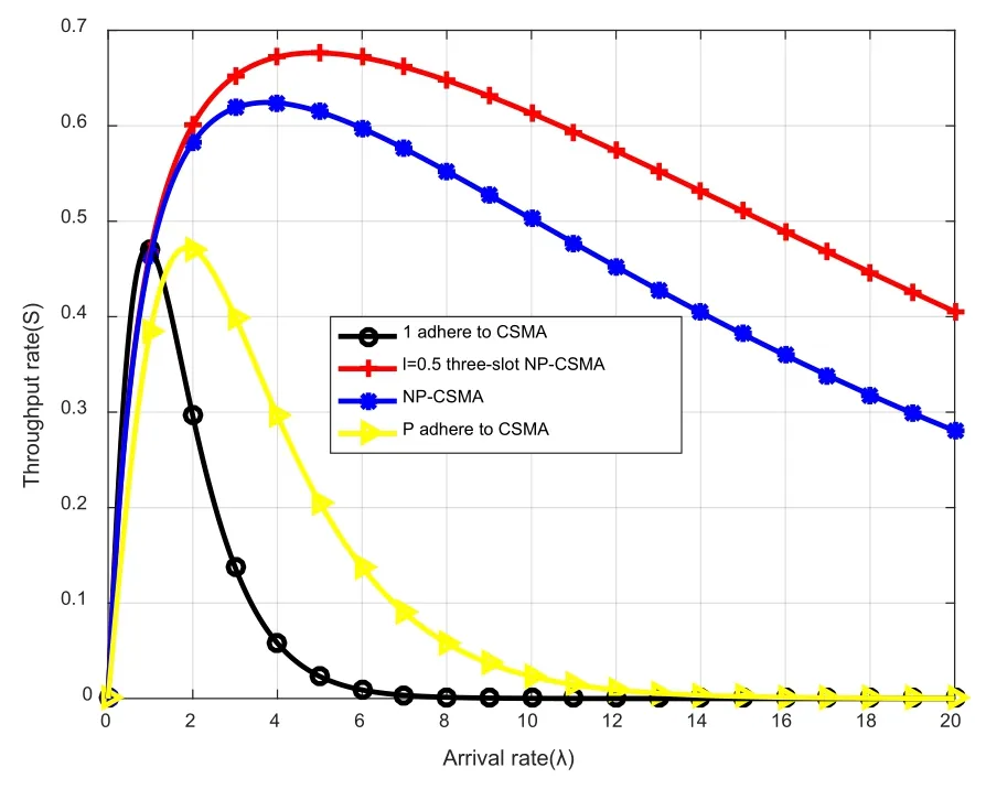
Figure 12:Throughput of different multiple access protocols
When the length of the idle time slot a is 0.1,the length of the collision time slotlis 0.5,and the length of the successful time slot is 1,the system throughput of the three-slot NP-CSMA at the arrival rate is simulated by MATLAB,and the following is obtained.The result shown in Fig.13.

Figure 13:Three-slot NP-CSMA throughput rate at l=0.5
Analysis Fig.13 shows that with the increase of the arrival rate,the throughput of the three-slot NP-CSMA increases sharply first,and the maximum value is 0.6764 when the arrival rate is 5,and then the throughput of the system decreases with the increase of the arrival rate.
When the length of the idle time slot a is 0.1 and the length of the successful time slot is 1,the system throughput of the three-slot NP-CSMA at different collision time slots is simulated by MATLAB,and the result shown in Fig.14 is obtained as follows[Zhou,Ding,Yang et al.(2017);Tadayon,Wang and Chen(2014)].
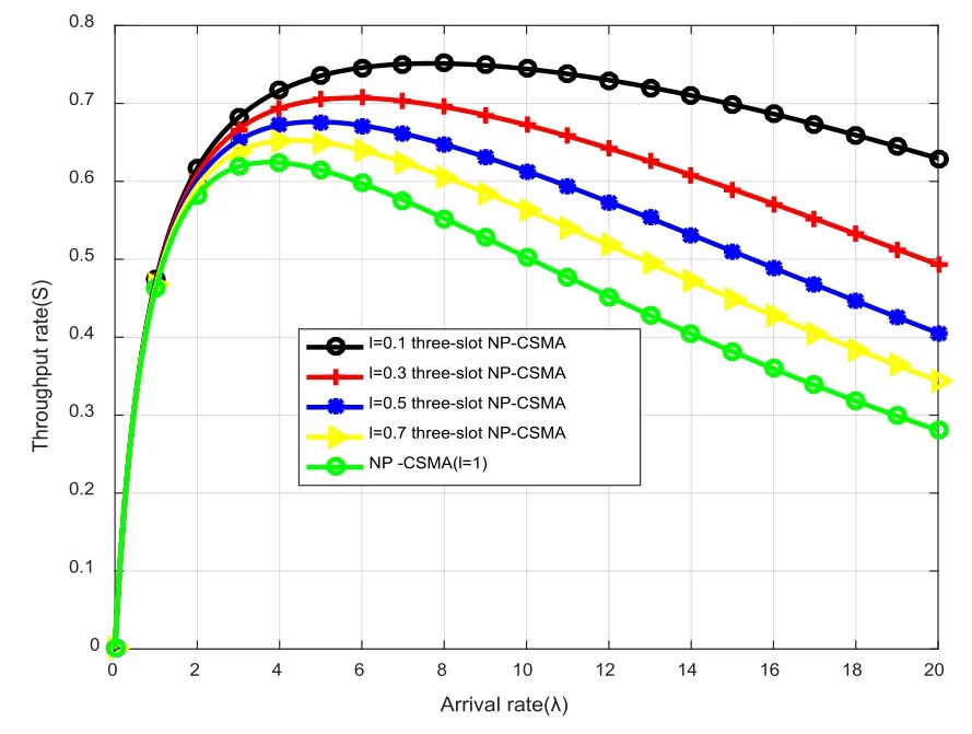
Figure 14:System throughput under different l values
Analysis of the above Fig.14 found:First,under different collision time slot lengths,the system throughput rate changes with the increase of the arrival rate;Secondly,when the arrival rate is greater than 3 and the arrival rate is the same,the larger the value of the collision time slot length l,the smaller the throughput rate of the system.
4.3.2 Analysis of throughput of three-slot NP-CSMA realized by FPGA
The Quartus software is used for synthesis and routing.The minimum clock period for the system is 10 ns,the length of information transmitted by the station is 8 bits,the idle time slot is a=0.1,the collision time slot isl=0.5,and the length of the time slot occupied by the idle information is 80 ns,the length of the time slot occupied by the successfully transmitted packet is 800 ns,and the length of the time slot occupied by the collision packet is 400 ns.
The three-slot NP-CSMA system was designed by Quartus software.The statistical results obtained are shown in Tab.1 below:
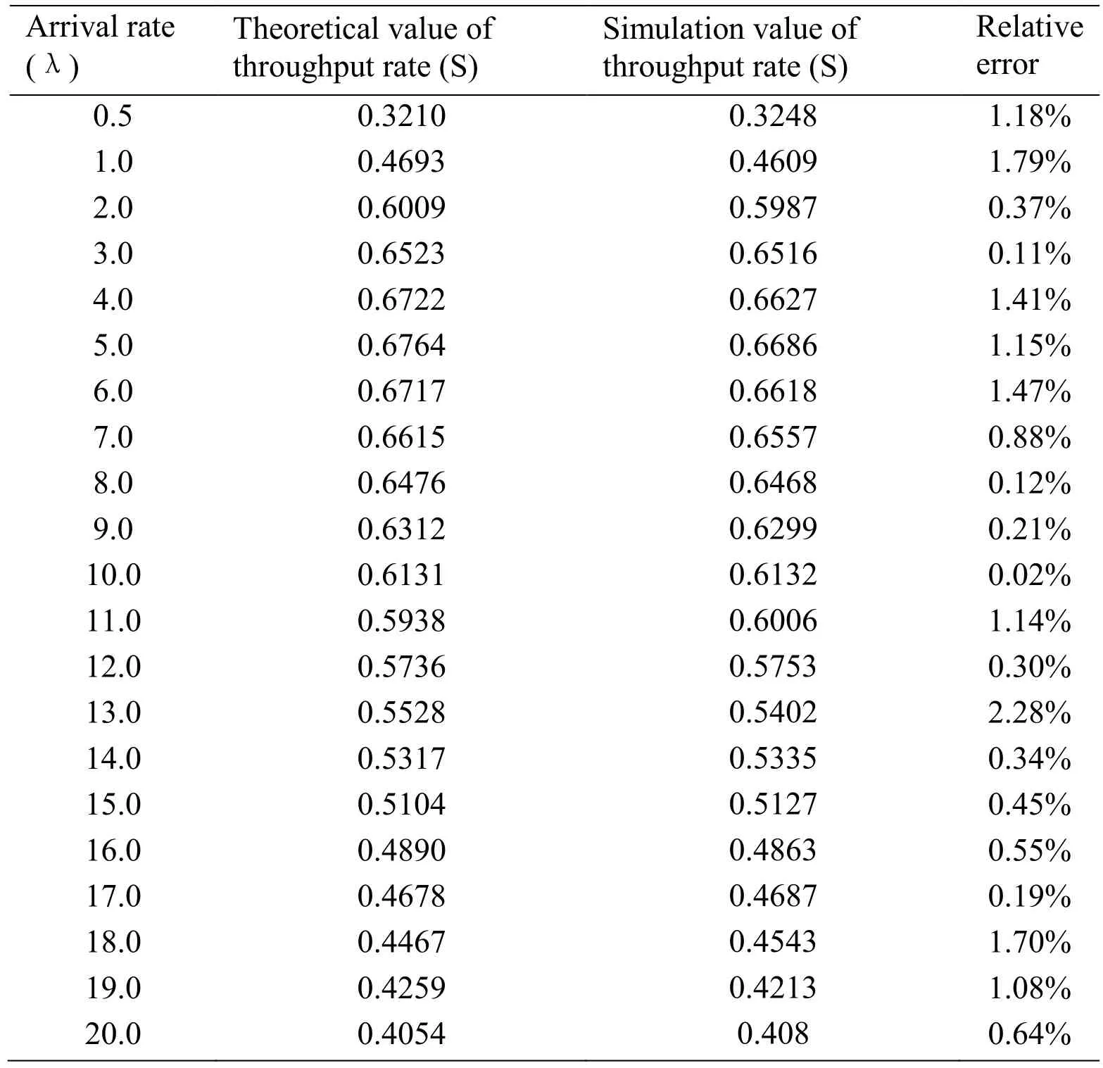
Table 1:Comparison of statistical and theoretical values of the system
Analysis Tab.1 gets:The statistical value of the throughput rate obtained by the three-slot NP-CSMA system designed by Quartus software is less than 0.01 compared with the theoretical value,indicating that the design system is reasonable.The theoretical values in the above table are directly calculated by the calculation formula of throughput rate.The statistical values in the table are obtained by running the three-slot NP-CSMA system in software Quartus.By comparing the statistical values and theoretical values,the rationality of the system design is proved.Figs.15-21 below shows the specific test results for the three-slot NP-CSMA system at the arrival rate λ=1 to λ=7.
(1)Set the simulation time to 1000 us,the total system information arrival rate λ=1,λ1=0.89,λ2=0.11.According to the above coefficient setting,the circuit simulation is completed,and the following timing simulation results are obtained as shown in the following figure:

Figure 15:Test simulation diagram of the system when λ=1
As shown in the Fig.15 above,the number of data transmission success event slots on the bus is 6338.The hardware circuit is simulated under the condition ofT=1000us,a=0.1,λ=1.According to formula(18),the simulation value of system throughput is 0.4609.
(2)Set the simulation time to 1000us,the total system information arrival rate λ=2,λ1=1.86,λ2=0.14.According to the above coefficient setting,the circuit simulation is completed,and the following timing simulation results are obtained as shown in the following figure:

Figure 16:Test simulation diagram of the system when λ=2
As shown in the Fig.16 above,the number of data transmission success event slots on the bus is 8232.The hardware circuit is simulated under the condition ofT=1000us,a=0.1,λ=2.According to formula(18),the simulation value of system throughput is 0.5987.
(3)Set the simulation time to 1000us,the total system information arrival rate λ=3,λ1=2.78,λ2=0.22.According to the above coefficient setting,the circuit simulation is completed,and the following timing simulation results are obtained as shown in the following figure:

Figure 17:Test simulation diagram of the system when λ=3
As shown in the Fig.17 above,the number of data transmission success event slots on the bus is 8959.The hardware circuit is simulated under the condition ofT=1000us,a=0.1,λ=3.According to formula(18),the simulation value of system throughput is 0.6516.
(4)Set the simulation time to 1000 us,the total system information arrival rate λ=4,λ1=3.18,λ2=0.82.According to the above coefficient setting,the circuit simulation is completed,and the following timing simulation results are obtained as shown in the following figure:

Figure 18:Test simulation diagram of the system when λ=4
As shown in the Fig.18 above,the number of data transmission success event slots on the bus is 9112.The hardware circuit is simulated under the condition ofT=1000us,a=0.1,λ=4.According to formula(18),the simulation value of system throughput is 0.6627.
(5)Set the simulation time to 1000us,the total system information arrival rate λ=5,λ1=4.2,λ2=0.8 According to the above coefficient setting,the circuit simulation is completed,and the following timing simulation results are obtained as shown in the following figure:

Figure 19:Test simulation diagram of the system when λ=5
As shown in the Fig.19 above,the number of data transmission success event slots on the bus is 9193.The hardware circuit is simulated under the condition ofT=1000us,a=0.1,λ=5.According to formula(18),the simulation value of system throughput is 0.6686.
(6)Set the simulation time to 1000us,the total system information arrival rate λ=6,λ1=5.13,λ2=0.87.According to the above coefficient setting,the circuit simulation is completed,and the following timing simulation results are obtained as shown in the following figure:

Figure 20:Test simulation diagram of the system when λ=6
As shown in the Fig.20 above,the number of data transmission success event slots on the bus is 9100.The hardware circuit is simulated under the condition ofT=1000us,a=0.1,λ=6.According to formula(18),the simulation value of system throughput is 0.6618.
(7)Set the simulation time to 1000us,the total system information arrival rate λ=7,λ1=6.14,λ2=0.86.According to the above coefficient setting,the circuit simulation is completed,and the following timing simulation results are obtained as shown in the following figure:

Figure 21:Test simulation diagram of the system when λ=7
As shown in the Fig.21 above,the number of data transmission success event slots on the bus is 9016.The hardware circuit is simulated under the condition ofT=1000us,a=0.1,λ=7.According to formula(18),the simulation value of system throughput is 0.6557.
5 Conclusion
Based on the analysis of NP-CSMA and three-slot NP-CSMA models,the hardware circuit design of three-slot NP-CSMA is designed by Quartus.After the design is completed,the throughput rate is verified,the error between the calculated throughput rate and the theoretical value is less than 0.01,indicating that the three-slot NP-CSMA system can be used for random access in wireless networks.The performance of three-slot NP-CSMA random multiple access protocol with delay,node energy consumption and throughput rate were simulated by MATLAB,the results are basically consistent with the theoretical values.Compared with other simulations of several multiple access protocols,it is found that the throughput of three-slot NP-CSMA is significantly higher than that of NP-CSMA,1-persistent CSMA,and P-persistent CSMA,and it is more obvious when the arrival rate is relatively high.
Acknowledgements:This work was supported by the National Natural Science Foundation of China(61461053,61461054,61072079,61463049);The Financial Support of Yunnan University(No.XT412004).
杂志排行
Computer Modeling In Engineering&Sciences的其它文章
- A Self-Organizing Memory Neural Network for Aerosol Concentration Prediction
- CHT/CFD Analysis of Thermal Sensitivity of a Transonic Film-Cooled Guide Vane
- Suppression of Ambipolar Conduction in Schottky Barrier Carbon Nanotube Field Effect Transistors:Modeling,Optimization Using Particle Swarm Intelligence,and Fabrication
- 3D Bounding Box Proposal for on-Street Parking Space Status Sensing in Real World Conditions
- IoT Based Approach in a Power System Network for Optimizing Distributed Generation Parameters
- Experimental Study and Finite Element Analysis on Ultimate Strength of Dual-Angle Cross Combined Section Under Compression
