The detrimental effect of autofrettage on externally cracked modern tank gun barrels
2019-05-24PerlSaley
M.Perl,T.Saley
Pearlstone Center for Aeronautical Engineering Studies,Department of Mechanical Engineering,Ben-Gurion University of the Negev,Beer-Sheva,84105,Israel
Keyw ords:Gun barrel Sw age and hydraulic autofrettage External crack 3-D Finite element
A B ST R A C T Overstraining gun tubes has a tw ofold advantage.First,it enables the increase of the Safe Maximum Pressure(SMP)in the tube,resulting in a higher muzzle velocity w hich extends the gun's range and its projectile kinetic energy.Second,it reduces the tube's susceptibility to internal cracking w hich prolongs its fatigue life.Unfortunately,autofrettage also bears an inherent detrimental effect as it considerably increases the tensile hoop stress at the outer portion of the barrel's wall,which enhances external cracking of the tube by increasing the prevailing Stress Intensity Factor(SIF).In order to quantify this disadvantageous effect,3-D Mode I SIFs distributions along the front of a single external radial semielliptical crack initiating from the outer surface of an autofrettaged modern gun barrel,overstrained by either the Sw age or the Hydraulic autofrettage processes,are evaluated.The analysis is performed by the f i nite element(FE)method,using singular elements along the crack front.Innovative residual stress f i elds(RSFs),incorporating the Bauschinger effect for both types of autofrettage are applied to the barrel.Hill's[1]RSFis also applied to the tube for comparison reasons.All three RSFs are incorporated in the FE analysis,using equivalent temperature f i elds.Values for KIA-the SIFresulting from the tensile residual stresses induced by autofrettage are evaluated for:a typical barrel of radii ratio R o/R i=2,crack depth to w all-thickness ratios(a/t=0.005-0.1),crack ellipticities(a/c=0.2-1.0),and f i ve levels of Sw age,Hydraulic and Hill's autofrettage(ε=40%,60%,70%,80%,and 100%).In total,375 different 3-D cases are analyzed.The analysis demonstrates undoubtedly the detrimental effect of all types of autofrettage in increasing the prevailing effective stress intensity factor of external cracks,resulting in crack initiation enhancement and crack grow th rate acceleration w hich considerably shortens the total fatigue life of the barrel.Nonetheless,the detrimental effect is autofrettage-type dependent.Sw age and Hydraulic autofrettage RSFs differ substantially from each other.The disadvantageous effect of Sw age autofrettage is much greater than that resulting from Hydraulic autofrettage.The results also emphasize the signi f i cance of the Bauschinger effect and the importance of the 3-D analysis.
1.Introduction
Gun barrels,as w ell as other cylindrical pressure vessels,have been autofrettaged for more than a hundred years in order to improve their operational performance.A favorable compressive residual hoop stress is induced at the gun's bore as a result of overstraining.This compressive stress at the tube's w all inner portion has a dual favorable effect.On the one hand,it enables to increases the allow able internal pressure in the tube,resulting in a higher muzzle velocity,w hich in turn extends the gun's range and its munitions kinetic energy.On the other hand,it reduces its susceptibility to internal cracking,w hich prolongs its fatigue life.At the same time,unfortunately,autofrettage also bears an inherent detrimental effect as it induces tensile residual hoop stresses at the outer portion of the barrel's w all,w hich boosts external cracking of the tube by increasing the prevailing Stress Intensity Factor(SIF)for cracks emanating from the outer surface of the barrel.Tw o processes are commonly used to overstrain gun barrels:Hydraulic autofrettage and Sw age autofrettage.Both create similar patterns ofresidual stress f i elds,yet of different distributions and magnitudes.
While the bene f i cial effect of realistic autofrettage has been thoroughly researched by among others Perl and Saley[2,3],the detrimental effect of overstraining has not been studied at all.For obvious mechanical reasons,the outer surface of barrels may bear functional geometrical discontinuities such as keyseats,grooves,part-through holes,etc.,as w ell as scratches.Under operational conditions,the outer surface of the barrel is subjected to the cyclic action of high pressure pulses during f i ring,and is exposed to corrosive materials and an aggressive environment.The presence of the stress concentrators,the repeated loading and the corrosive environment may result in initiating one or a few 3-D,semi-elliptical radial cracks from the barrel's external surface into the barrel's w all.The largest of these cracks,comm only coined“the major crack”,w hich grow s due to cyclic loading,may become critical,and cause catastrophic barrel failure.
The fatigue process of such cracks is governed by the prevailing combined Stress Intensity Factor(SIF)KIN[3]w hich,in this case,consists of tw o components:KIP-the SIFdue to internal pressure,and KIA-the positive SIF due to the tensile residual stresses induced by autofrettage i.e.,KIN=KIP+KIA.Several results are presently available for KIPfor external cracks in thick-w alled cylindrical pressure vessels by,among others,Raju and New man[4],Zheng et al.[5],Anderson[6]and Gerasimenko[7].How ever,to the best of the authors know ledge,values for KIAw ere never evaluated for external cracks in autofrettaged cylinders.It is,therefore,the purpose of the present analysis to evaluate KIA,the positive SIFdue to autofrettage,for a single external crack prevailing in an overstrained modern gun barrel applying an innovative,realistic,experimentally based autofrettage model,hereafter explained,w hich enables a very accurate replication of both Hydraulic and Sw age autofrettage residual stress f i elds(RSFs)in a fully or partially overstrained barrel.For comparison reasons,Hill's[1]RSF is also applied.SIFs for a typical modern tank gun barrel of radii ratio Ro/Ri=2,for crack depth to w all-thickness ratios(a/t=0.005-0.1),crack ellipticities(a/c=0.2-1.0),and f i ve levels of Sw age,Hydraulic and Hill's autofrettage(ε=40%,60%,70%,80%,and 100%)are evaluated.This particular range of relative crack depth of a/t=0.005 to 0.1 is chosen to enable the comparison w ith internal cracks[2].
2.Autofrettage and its simulation
There has been a continuous effort to increase the pressure carrying capacity of gun barrels aiming at extending their f i ring range since the 17th century.A new metal fabrication process was suggested to achieve this goal by a French Artillery of f i cer Col.L.Jacob[8]at the beginning of the 20th century.Since that time,this process,know n as autofrettage-self-hooping in French,has been used in gun barrel manufacturing,and in a variety of other cylindrical pressure vessel applications such as nuclear reactor vessels,high pressure oil f i eld pipes,low-density polyethylene processing etc.The process of autofrettage,initially meant to enable an increase in the gun's internal pressure,w as also found to reduce the gun's sensitivity to internal cracking,i.e.,inhibiting crack initiation and moderating crack grow th rate,thus extending remarkably the barrel's fatigue life.
The f i rst process to be used for barrel overstraining w as Hydraulic Autofrettage.In the f i rst stage of this process,the tube is subjected to an increasing internal hydraulic pressure until plastic deformation onsets at the bore.As pressure is further increased,the plastic deformation progresses through the tube's w all until it reaches the outside surface and the barrel is then considered fully autofrettaged.In case the process is interrupted w hile the plastic deformation moved only through part of the tube's w all,the tube is only partially autofrettaged.In the second stage,the hydraulic pressure is released and elastic recovery occurs resulting in a residual stress f i eld through the cylinder's w all.The residual hoop stress component is compressive at the inner portion of the tube's w all and tensile at its outer part.The largest residual compressive hoop stress occurs at the bore,and it monotonically changes into a residual tensile hoop stress reaching its maximum at the external surface of the barrel.
Due to the very high pressure required,the process of Hydraulic Autofrettage is slow,dangerous,and expensive.Consequently,in the early 1960's Davidson et al.[9]suggested a new process:Sw age Autofrettage.In this process overstraining is accomplished by pushing an oversized tungsten carbide mandrel through the tube's blank,using a solid steel ram.This faster,safer,and cheaper process has been w idely used since its introduction in gun barrel manufacturing,as w ell as in many other industries.Until recently[10,11],the tw o processes w ere considered to yield the same pressure carrying capacity,provided the tube w as overstrained to the same level.How ever,the factual data,accumulated mainly by the gun barrel industry,identi f i ed the clear advantages of Sw age autofrettage over Hydraulic autofrettage in creating a higher residual hoop stress at the bore,and thus,further increasing the tubes pressure carrying capacity and extending the barrel's fatigue life.
The residual stress f i eld induced by autofrettage serves as the key input to the stress analysis of both the intact and the cracked tubes.In spite of the fact that the tw o types of autofrettage have been in use for many years,the evaluation of their RSFs is complicated because of detailed elasto-plastic characteristics of the tube's material.Furthermore,w hile a tw o dimensional analysis proves satisfactory for Hydraulic autofrettage,Sw age autofrettage necessitates a 3-D analysis to account for the three dimensionality of the process.
Many attempts have been made by e.g.,[1,11-18]to calculate the RSFdue to Hydraulic and Sw age autofrettage.How ever,only in the last decade Perl and Perry[19,20]suggested a comprehensive 3-D model w hich enables an accurate evaluation of both Hydraulic and Swage autofrettage RSFs.This innovative model,is totally based on the experimentally measured stress-strain curve under repeated reversed loading,thus enabling an accurate characterization of the material's behavior including the Bauschinger effect in both tension and compression.
Once the material's characteristics of Cr-Ni-Mo-V modern gun barrel steel(a modi f i ed AISI 4340)are experimentally determined,the new model is applied to evaluate the hoop residual stress component for Hydraulic,Sw age and Hill's autofrettage for a partially(ε=40%,70%)or fully(100%)overstrained barrel presented in Fig.1.
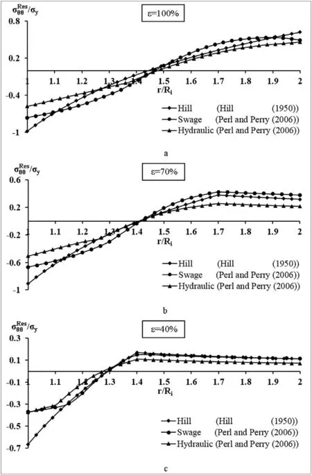
Fig.1.The distribution of the residual hoop stress component for Hydraulic,Swage and Hill's autofrettage in a partially or fully overstrained barrel of R o/R i=2(a)ε=100%,(b)ε=70%,and(c)ε=40%.
The hoop residual stress(Fig.1)is compressive at the inner portion of the barrel's w all and becomes tensile at its outer part.High internal pressure is applied to the barrel during the f i ring process creating a tensile hoop stressthrough the barrel's wall w ith a maximum at the bore and a minimum at the outer surface of the tube.When the residual stresses are superimposed on the stresses due to internal pressure,the compressive residual hoop stressσResθθ proves bene f i cial as it reduces the effective hoop stress at the inner portion of the barrel.The tensile part of the residual stress how ever,isdetrimental as it increasesthe hoop stressat the outer part of the tube.Tables 1 and 2 respectively represent the values of the residual hoop stressat the inner and the outer surfacesof the tube,for the three types of autofrettage.
The largest differences betw een the RSFs of the three types of autofrettage occur at the inner and the outer surfaces of the barrel's wall.When considering the bore of a fully autofrettaged barrel(Fig.1(a)),Hill's model predicts the highest negativeat the bore.The realisticat the bore due to Sw age and Hydraulic autofrettage is22%smaller in absolute value for the former,and 41%for the latter than Hill's.This discrepancy results from the decrease in yield stressin compression due to the Bauschinger effect w hich is accounted for by the new model[19,20],w hile ignored by Hill's.Furthermore,in both autofrettage processes,upon unloading the barrel,re-yielding may occur at its inner w all,resulting in a further decrease in the yield stress.The differences innear the bore betw een the three RSFs have a major impact on the fatigue life of the barrel.Higher negativeσreduces the susceptibility to crack initiation and slow s dow n crack grow th rate,yielding a longer fatigue life.Whereas realistic fatigue lives for the barrel are yielded by Sw age and Hydraulic autofrettage,Hill's“ideal”model highly overestimates its value.
When considering the outer surface of a fully autofrettaged barrel,Hill's model predicts the highest positive(Fig.1(a)).The realisticat the outer surface of the barrel due to Swage and Hydraulic autofrettage is 21%and 26%smaller in value than Hill's respectively.Low er positivedecreases the sensitivity to external cracking and slows dow n crack grow th rate.Hill's model considerably underestimates fatigue life in this case,w hile Sw age and Hydraulic autofrettage types yield realistic fatigue lives for the barrel.
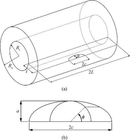
Fig.2.(a)The cylinder with one external crack.(b)The parametric angleφde f i ning the points on the crack front.

Table 1The relative residual hoop stressσRθθe s/σy at the inner surface of the barrel r=R i.

Table 2The relative residual hoop stressσRθθe s/σy at the outer surface of the barrel r=R o.
At the inner portion of a partially autofrettaged barrel(ε=60%-80%),the patterns of the three RSFs are similar to that of the fully autofrettaged tube,though getting lower in absolute magnitude as the level of autofrettage decreases(cf.Fig.1(b)and(c)to Fig.1(a)).At the outer portion of a partially autofrettaged barrel,the RSF is different in both pattern and magnitude than in the case of full autofrettage.The magnitude of all RSFs decreases as the level of autofrettage decreases as can be anticipated.Furthermore,in the case ofε=70%(Fig.1(b),and Table 2),Sw age autofrettage predicts the largest positiveσResθθ,w hile Hydraulic autofrettage predicts the smallest one,w ith an intermediate value for Hill's RSF.Hill's and Hydraulic autofrettage RSFs are 16%and 44%lower than Sw agerespectively.In the case ofε=40%(Fig.1(c),and Table 2),Sw age and Hill's autofrettage RSFare practically identical,w hile,due to Hydraulic autofrettage,is 38%low er.
The discrete values of RSFdistribution are incorporated in the FE analysis in each case,using an equivalent temperature f i eld w hich emulates them very accurately.The discrete values of the equivalent temperature f i eld are calculated using the general algorithm developed by Perl[21].A detailed description of obtaining the equivalent temperature f i eld and its embodiment in the FEanalysis is given in Perl[21].In all the cases herein treated,the RSFs resulting from the equivalent temperature f i eld are compared to the original RSFs and are all found to be practically identical.
3.Three dimensional analysis
The three dimensional analysis of the externally cracked barrel is based on Linear Elastic Fracture Mechanics(LEFM).The tube is modeled as an elastic cylinder of inner radius Ri,outer radius Ro,and w all thickness t(Ro/Ri=2,and t=Ri)and length,2L.The cylinder contains an external radial semi-elliptical crack of length 2c and depth a.The cylinder containing one crack is presented in Fig.2(a).In order to avoid end effects,the ratio of the cylinder's length to its inner radius,L/Ri,is taken to be at least as 4.The barrel is assumed to be made of a typical Cr-Ni-Mo-V barrel steel(a modi f i ed AISI 4340)w ith an initial yield stress ofσy=1050 MPa,Young modulus E=203 GPa and Poisson's ratioν=0.3.As a modern tank gun is considered,the internal pressure is set to be p=608 MPa.All the SIFs are calculated by tw o methods:the displacement extrapolation method(DEM)and the J-integral.In the case of very shallow cracks of a/t=0.005,SIFs are calculated along the crack front at intervals ofΔφ=3.6°for cracks of a/c≥0.4,and at intervals ofΔφ=2.25°for cracks of a/c=0.2.For deeper cracks,a/t≥0.01,SIFs are calculated along the crack front at intervals ofΔφ=1.8°for cracks of a/c≥0.4,and at intervals of Δφ=1.125°for cracks of a/c=0.2.
4.The f i nite elem ent m odel
Because of its many symmetries only a quarter of the cylinder is analyzed(see Fig.2(a)).The autofrettage RSF is induced in the FE model by an equivalent temperature f i eld as previously explained.The model is solved using the commercial ANSYS13.0 FEcode[22].To accommodate the singular stress f i eld in the vicinity of the crack front,this area is covered w ith a layer of 20-node isoparametric brick elements collapsed to w edges,forming singular elements at the crack front[23].On top of this layer,at least four additional layers,consisting of 20-node isoparametric brick elements,are meshed(see[2]).The rest of the model is divided into tw o zones.Zone I,the f i rst quarter of the cylinder's length near the crack,is meshed w ith tetrahedron elements,w hile Zone II,the rest of the cylinder is meshed w ith brick elements.Near the crack front,the elements are chosen to be small,and their size is gradually increased w hen moving aw ay from the crack.SIFs are extracted using tw o methods built into ANSYS:The J-integral[24],and the crack-face displacement extrapolation method.SIFs are calculated at equally spaced discrete points along the crack front.
4.1.Validation of the FEmodel
Since presently there are no values for KIAfor external cracks in autofrettaged cylinders,the FE model is f i rstly validated by calculating KIPdistribution along a semi-circular external crack of depth a/t=0.1,and comparing it w ith the results obtained in API 579-1[25]using the w eight function method.The results presented in Fig.3 show that the present and API 579-1 results are w ithin less than 1%except for the external surface point(φ=0°)w here they differ by about 4.5%.In order to further validate the model,KIAdistribution along the front of a semi-circular external crack of depth a/t=0.1 prevailing in a fully autofrettaged cylinder is evaluated by tw o independent methods:The J-integral method and the displacement extrapolation procedure,w hich then are compared to each other in Fig.4.The maximal difference of about 1.5%betw een the tw o methods occurs atφ=0°,at the intersection of the crack plane w ith the outer surface of the cylinder.As one moves aw ay from this point,the difference in KIA/K00drops to about 0.2%.
In order to maintain high accuracy of the evaluated SIFs,convergence tests w ere conducted for KIA.The value of KIA/K00at the deepest point(φ=90°)of a semi-circular crack of depth a/t=0.1 served as a convergence criterion.KIA/K00w as evaluated for a fully autofrettaged(Hill's model)barrel.Fig.5 represents the convergence of KIA/K00as a function of the number of DOF.The results indicate that above 1,200,000 DOF,the error is less than 0.02%.Thus,in order to ensure high accuracy,1,600,000 DOF are employed for all cases.
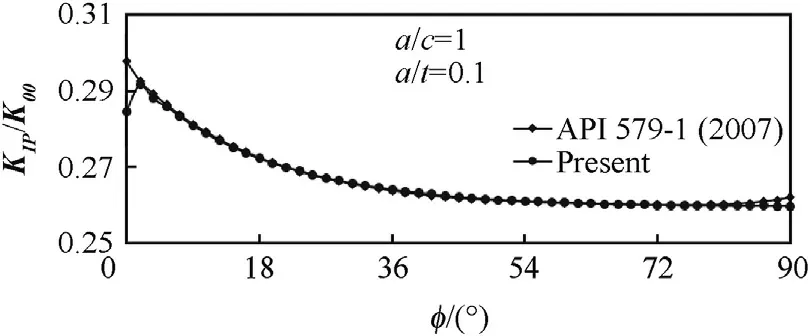
Fig.3.A comparison betw een the present distribution of KIP/K00 along the front of a semi-circular external crack of depth a/t=0.1,in a fully autofrettaged barrel of R o/R i=2 evaluated by the DEM method and those of API 579-1[25]evaluated by the w eight function method.
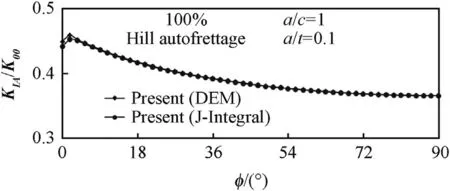
Fig.4.A comparison betw een the distribution of KIA/K00 along the front of a semicircular,external crack of depth a/t=0.1,in a barrel of R o/R i=2 evaluated by the displacement extrapolation method(DEM)and the one obtained by the J-integral.
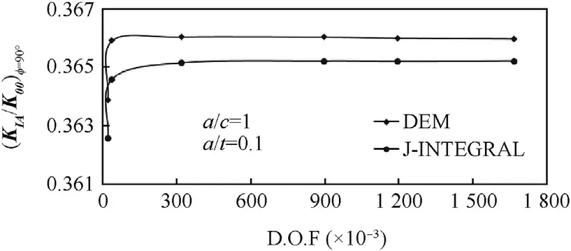
Fig.5.KIA/K00(φ=90°)as a function of the number of DOF for a semi-circular,a/c=1,external crack of depth a/t=0.1,in a fully autofrettaged barrel of R o/R i=2.
5.Num erical results and discussion
Unlike the case of an internal crack,w here KIAis usually negative reducing the effective SIF,in the case of external cracks,KIAvalues are usually positive,therefore,increasing the effective SIF w hich has a disadvantageous effect on the barrel's fatigue life.In the present analysis KIAvalues are calculated for external radial cracks prevailing in a typical barrel of radiiratio Ro/Ri=2 for a w ide range of relevant crack depth to w all-thickness ratios a/t=0.005,0.01,0.04,0.07,and 0.1,for various crack ellipticities a/c=0.2,0.4,0.6,0.8,and 1.0,and for f i ve levels of Sw age,Hydraulic and Hill's autofrettage ofε=40%,60%,70%,80%,and 100%.In total,375 different 3-D external crack cases are analyzed.In order to enable future comparison and superposition,the SIFs KIAand KIPare normalized further on,w ith respect to:

5.1.KIA distribution along an external-crack's front in a fully autofrettaged barrel
KIAvalues for all crack con f i gurations in a fully autofrettaged gun barrel are calculated for Hydraulic,Sw age and Hill's autofrettage RSFs and are normalized w ith respect to K00.In the analysis to follow,KIAdistributions along the crack front are separately presented for semi-circular cracks a/c=1.0 and for semi-elliptical ones a/c<1.0.
5.1.1.Semi-circular cracks a/c=1.0
Typical distributions of KIA/K00along the crack front of an external semi-circular crack of depth a/t=0.005 and 0.1,prevailing in a fully autofrettaged barrel are presented in Figs.6 and 7 respectively.Generally speaking,there are tw o patterns of KIA/K00distributions.The f i rst one has its maximum atφ=0°and its minimum atφ=90°.This type of distribution occurs in the cases of Hydraulic and Hill's autofrettage for cracks of depths a/t=0.005 and 0.1,and only for shallow cracks a/t=0.005 in the case of Sw age autofrettage(see Figs.6 and 7).The second distribution pattern is coined Iso-KIAas the distribution is almost even along the crack front.This distribution is characteristic only of deep cracks,e.g.,a/t=0.1,in the case of Sw age autofrettage(see Fig.7).
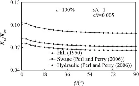
Fig.6.KIA/K00 vs.φalong the front of a semi-circular crack of depth a/t=0.005.in a fully autofrettaged cylinder.
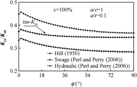
Fig.7.KIA/K00 vs.φalong the front of a semi-circular crack of depth a/t=0.1 in a fully autofrettaged cylinder.
From Figs.6 and 7 it is evident that the magnitude of KIAdiffers considerably betw een the three types of autofrettage:Hill's yielding the highest KIAvalue,Sw age autofrettage predicting an intermediate value,and Hydraulic autofrettage producing the low est KIA.These results have a direct impact on the effective SIF and thus on the fatigue life of the barrel.In this case Hill's“ideal”RSF excessively and non-realistically underestimate the total fatigue life of the barrel.
Table 3 summarizes the ratios betw een the maximum values of these distributions,w hich occur atφ=0°,for the f i ve crack depths herein evaluated.The ratios betw een the magnitudes of the maximum SIFdue to the three types of autofrettage are practically crack depth independent.On the average in this case,Sw age and Hydraulic autofrettage produce SIFs w hich are about-19%and 26%low er than Hill's respectively.
5.1.2.Semi elliptical cracks a/c<1.0
The distribution of KIA/K00along the crack front of an external radial crack of a/c<1.0 is ellipticity dependent:
5.1.2.1.Cracks of ellipticity 1.0>a/c>0.8.When crack ellipticity is larger than a/c=0.8,KIA/K00,distributions along the crack front have a similar pattern to that of semi-circular cracks(as in Figs.6 and 7),bearing their maximal values near the outer surface of the barrel.

Table 3KIA m ax for full Sw age and Hydraulic autofrettage relative to Hill's solution for semi-circular external cracks of various depths.
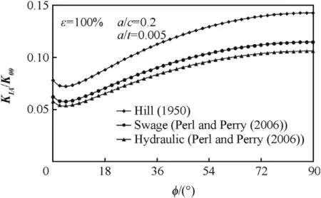
Fig.8.KIA/K00 vs.φalong the front of a slender semi-elliptical external crack.of a/c=0.2 and depth a/t=0.005 in a fully autofrettaged cylinder.
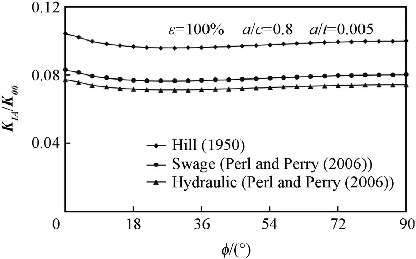
Fig.10.KIA/K00 vs.φalong the front of an iso-semi-elliptical crack of a/c=0.8 and depth a/t=0.005 in a fully autofrettaged cylinder.
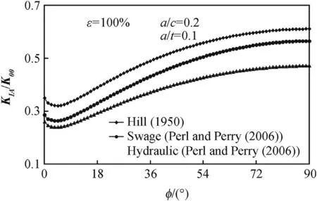
Fig.9.KIA/K00 vs.φalong the front of a slender semi-elliptical external crack.of a/c=0.2 and depth a/t=0.1 in a fully autofrettaged cylinder.
5.1.2.2.Cracks of ellipticity 0.6>a/c≥0.2.Typical distributions of KIA/K00for slender cracks are presented in Figs.8 and 9 for a crack of ellipticity a/c=0.2 and depths a/t=0.005 and 0.1 respectively.The maximum value for both cracks occurs atφ=90°,the deepest point of the crack.,and the relations betw een KIA/K00values for the three autofrettage types presented in Table 4,are practically crack depth independent and are almost identical to those presented in Table 3 i.e.,≈0.81 and≈0.74.
5.1.2.3.Cracks of ellipticity 1.0≥a/c≥0.6.In this range of ellipticities,as the one presented in Figs.10 and 11,cracks are iso-KIcracks,having an almost uniform distribution of KIA/K00around the entire crack front.The more crack ellipticity deviates from the iso-KIrange,the higher the non-uniformity of KIA/K00distribution along the crack front as can be seen,for example,in Fig.12 for the three types of autofrettage andε=100%.Based on the present results,cracks can be considered as“iso-cracks”for Hill's autofrettage in the range of ellipticities of 0.8≥a/c≥0.6,for Hydraulic autofrettage 0.8≥a/c≥0.7 and for Sw age autofrettage 1.0≥a/c≥0.8.
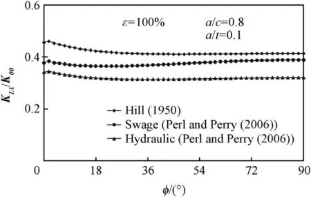
Fig.11.KIA/K00 vs.φalong the front of an iso-semi-elliptical crack of a/c=0.8 and depth a/t=0.1 in a fully autofrettaged cylinder.
5.2.KIA distribution along an external-crack's front in a partially autofrettaged barrel
Most gun barrels are commonly only partially autofrettaged to aboutε=70%,since the marginal bene f i t in increasing the level of autofrettage fromε=70%toε=100%is about 10-15%[2]in augmenting the allow able internal pressure.How ever,this increase in the level of autofrettage has a major disadvantage of enhancingexternal cracking of the barrel.A second reason for investigating the in f l uence of partial autofrettage is the fact that during the barrel'slife the residual stress f i eld due to autofrettage deteriorates,resulting in a lower overstrain level,w hich in turn affects its fatigue life.

Table 4KIA m ax for full Sw age and Hydraulic autofrettage relative to Hill's solution for semi-elliptical external cracks of a/c=0.2 for various crack depths.
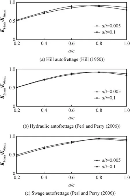
Fig.12.The non-uniformity of KIA distribution along the crack front vs.crack ellipticity for the three types of autofrettage andε=100%.
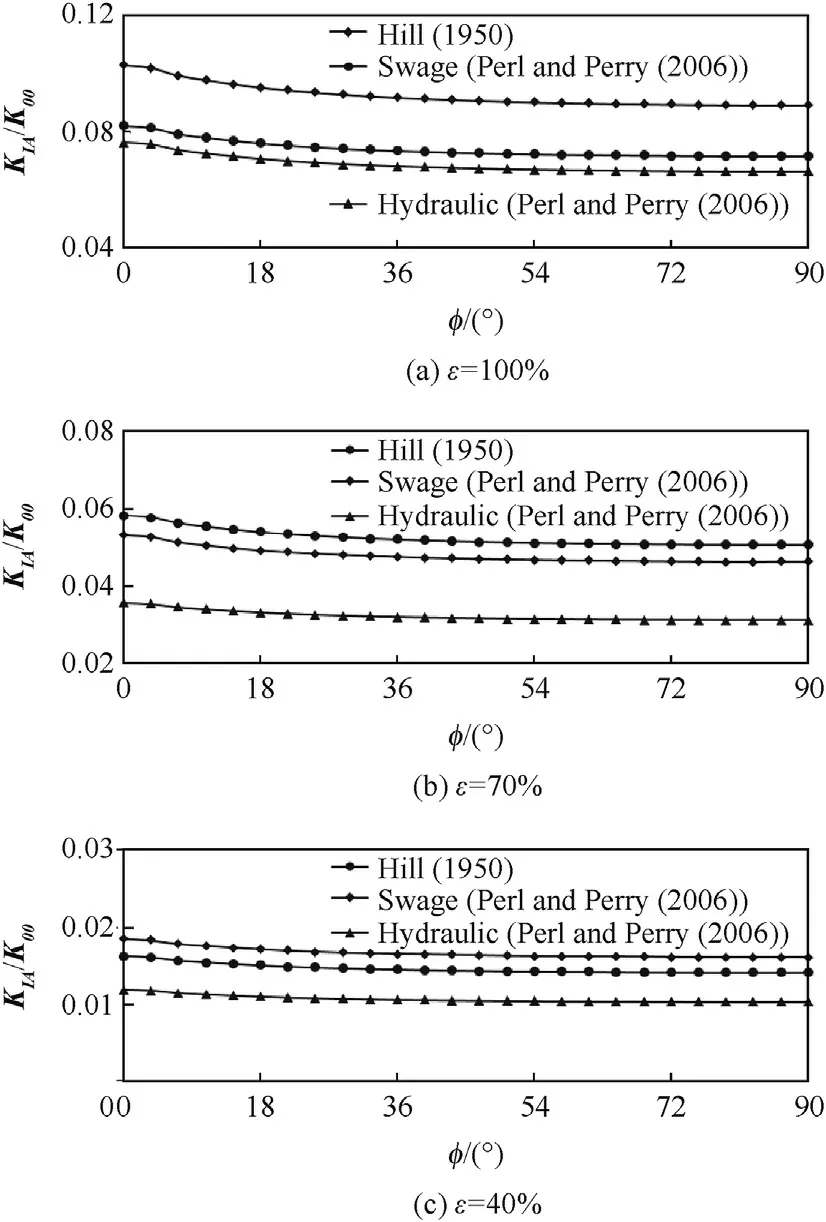
Fig.13.KIA/K00 vs.φfor an external radial semi-circular crack of depth a/t=0.005 prevailing in a barrel overstrained to three different levels of Hill's,Sw age and Hydraulic autofrettage:ε=100%,70%,and 40%.
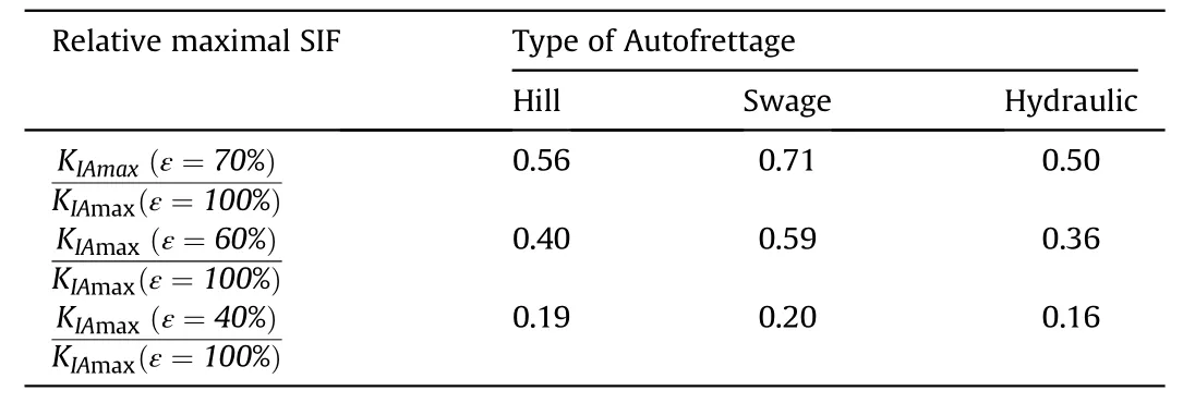
Table 5Values of KIA m ax for an external crack in a partially autofrettaged barrel(ε=70%,60%,40%)relative to a fully overstrained tube for the three types of autofrettage.
Fig.13(a-c)represents KIA/K00for an external radial semicircular crack of depth a/t=0.005 prevailing in a barrel overstrained to three different levels of Hill's,Sw age and Hydraulic autofrettage:ε=100%,70%,and 40%.As anticipated,the value of KIAdecreases as the level of autofrettage decreases.The relative values of KIAmaxforε=70%,60%,and 40%w ith respect toε=100%for the three types of autofrettage are given in Table 5.
From Table 5 it can be seen that lowering the level of autofrettage fromε=100%toε=70%reduces considerably the detrimental effect on an external crack by about 30%for Sw age autofrettage and 50%for hydraulic autofrettage.
6.Concluding rem arks
The distributions of KIAalong the front of a single external radial crack in an overstrained smooth gun barrel are evaluated for numerous crack con f i gurations evaluating the effects of the type and level of autofrettage and of the crack's geometry.KIAvalues are evaluated for three types of autofrettage:Swage,Hydraulic and Hill's,for f i ve levels of overstrainingε=40%,60%,70%,80%,and 100%,for crack depths of a/t=0.005,0.01,0.04,0.07,and 0.1,and for various crack ellipticities a/c=0.2,0.4,0.6,0.8,and 1.0.
In spite of the fact that all types of autofrettage herein discussed have an adverse effect on external cracks,they differ considerably in the magnitude of this negative effect.The detrimental effect of both Hydraulic and Sw age autofrettage on the external cracking of a fully autofrettaged gun barrel is found to be much smaller than that anticipated by Hill's“ideal”autofrettage.This results from the fact that Hill's RSFignoresthe Bauschinger effect.The incorporation of the Bauschinger effect in the cases of Swage and Hydraulic autofrettage resultsin a substantial reduction of the material'syield stress and thus,considerably reducing KIAvalues.
In the case of partial autofrettage,the detrimental effect of the three RSFs is somew hat different.All three RSFs become w eaker as the level of autofrettage decreases,having a less severe detrimental effect on the barrel's life.In the case of 70%overstraining,Sw age autofrettage has a 78%higher detrimental effect than Hydraulic autofrettage,w hile forε=40%,the adverse effect of Sw age overstraining is 61%higher than that of Hydraulic overstraining.
Reducing the level of Sw age and Hydraulic overstraining from ε=100%toε=70%has only a marginal effect on the barrel's pressure capacity and on the bene f i cial effect on internal cracking.How ever,it considerably reduces the unfavorable effect on external cracking.
The evaluation of the combined effect of overstraining and pressurization of the barrel on external cracking is presently underw ay.The combined SIFs KIN=KIP+KIAare to be determined as w ell as the maximum value KINmaxw hich controls fracture processes.The results of this study w ill be presented elsew here.
杂志排行
Defence Technology的其它文章
- Magnesium nanocomposites:An overview on time-dependent plastic(creep)deformation
- Ballistic performance of tungsten particle/metallic glass matrix composite long rod
- A density functional study on some cyclic N10 isomers Lemi Türker
- Information hiding w ith adaptive steganography based on novel fuzzy edge identi f i cation
- Optimization of gas tungsten arc w elding parameters for the dissimilar welding between AISI 304 and AISI 201 stainless steels
- Parametric study of single con f i ned fragment launch explosive device
