Residual stresses of polycrystalline CBN abrasive grits brazed with a high-frequency induction heating technique
2019-04-28WeiXUYejunZHUBicunDUWenfengDING
Wei XU , Yejun ZHU , Bicun DU , Wenfeng DING ,*
a College of Mechanical and Electrical Engineering, Nanjing University of Aeronautics and Astronautics, Nanjing 210016, PR China
b Department of Computer Engineering, Chongqing Aerospace Polytechnic, Chongqing 400021, PR China
KEYWORDS Brazing residual stress;Finite element analysis;High-frequency induction heating;Polycrystalline CBN grit
Abstract Residual stresses produced in polycrystalline CBN abrasive grits during a high-frequency induction brazing process are calculated by using finite element analysis,with a consideration of the nonuniform temperature distribution in the induction brazing model. The influences of induction brazing parameters on the residual stresses of polycrystalline CBN abrasive grits have been analyzed, including the embedding depth, grit side length, etc. Results obtained show that the tensile stress with a 40% embedding depth is 292 MPa, which is the minimum on the bonding interface compared with other embedding depths. Meanwhile, the maximum tensile stress is 575 MPa, with an increase of 59%compared with that of a grit side length of 50 mm.Finally,the simulation results of the brazing residual stress of polycrystalline CBN abrasive grits have been conf irmed valid based on the residual stress measurement of the brazed monocrystalline CBN grit.
1. Introduction
Owing to the strong grit-holding force and the suff icient chipstorage space of brazed abrasive wheels, single-layer brazed cubic boron nitride(CBN)abrasive wheels have broad application prospects in the machining process of difficult-to-cut metallic materials, such as nickel-based superalloy, titanium alloy, and bearing steel.1-5In a previous work, a highfrequency induction brazing technique, instead of the conventional vacuum-furnace brazing technique, has been utilized to manufacture single-layer CBN wheels, especially with a large dimension due to the induced small thermal deformation of the wheel substrate.6In addition, polycrystalline cubic boron nitride (PCBN) abrasive grains, which are synthesized by microcrystalline CBN particles and AlN ceramic binder under high temperature and high pressure, have an isotropic structure.7The unique structure overcomes the drawback of anisotropic monocrystalline CBN grits, which tend to a cleavage in grinding due to limited slipping planes.8
However,there are still challenges and difficulties in singlelayer brazed PCBN abrasive wheels manufacturing using a high-frequency induction brazing technique. Recent research has pointed out that the high tensile stress within a grit generated during the brazing process could result in grit fracture.9-12Nevertheless, the dimensions of PCBN grits in grinding are small (ranging from 50 μm to 400 μm), which makes stress measurement difficult.In comparison, the simulation and prediction of stresses distributions in some materials based on finite element analysis (FEA) have been widely utilized in recent years.13,14For example, Zohdi built a cooling-induced residual stresses model in heated particulate mixture depositions.15Wang et al. analyzed the residual stresses distribution in Si3N4/Invar joints through simulation,and results showed a good match with experimental ones.16In addition,Meng et al.analyzed the thermal effects on brazed diamond grains with FEA, and found brazing-induced compressive residual stress in diamond grits.17Chen et al.modeled the residual stress distribution in diamond grits during a brazing process, and showed that the maximum tensile stress occurred along the brazing bond.18Furthermore,Zhu et al.investigated the distribution of residual stress in brazed CBN abrasive grits during a vacuum-furnace brazing process with a uniform heating temperature distribution, and showed that the grit-brazing bound had the maximum tensile stress,and this was also independent of the bonding material and embedding depth.19However,Xu et al.pointed out that the temperature during a high-frequency brazing process changed more rapidly than that during a vacuum-furnace brazing process, which would affect the brazed PCBN grits stress distribution.20Hence, the residual stress distribution of PCBN abrasive grits are crucial during a high-frequency brazing process, and more in-depth research is needed.
The microstructure of a grit has been found to affect greatly the stress distribution in PCBN abrasive grits.21The Voronoi tessellation method has been widely utilized to build the microstructures of polycrystalline materials.22For example,Li et al.studied the mechanical property of tungsten-based bulk metallic glass matrix composites with the Voronoi tessellation technique.23Zhou and Huang used the Voronoi tessellation to represent microstructures of single-phase ceramic tool materials.24Meanwhile,Alveen et al.created a finite element model of PCBN materials with the Voronoi tessellation procedure,and analyzed the influence of microstructures on the fracture properties of PCBN materials for industrial applications.25
In this article, a microstructure model of a PCBN abrasive grit is firstly established using the Voronoi tessellation techniques. Then, the nonuniform temperature field of high-frequency induction brazing is applied to the model.The distribution of residual stress after induction brazing is studied,and the effects of different brazing process parameters on the residual stress are investigated.Finally,the accuracy of simulation results is compared with grinding experiments on PCBN abrasive grits.
2. FEA modeling of the brazing-induced residual stress of polycrystalline CBN grits
A two-dimensional (2D) high-frequency induction brazing FEA model of a polycrystalline CBN abrasive grit has been built to investigate the residual stress distribution, as shown in Fig. 1(a). The material model is composed of three parts,i.e., a steel wheel substrate, an Ag-Cu-Ti filler alloy, and an embedded polycrystalline CBN grit. The steel wheel substrate is truncated into a rectangular shape (5 mm×2 mm).The Ag-Cu-Ti filler alloy is 2 mm in length.The polycrystalline CBN grit is established based on the Voronoi partition method.As displayed in Fig.1(b),the polycrystalline CBN grit is a positive hexagon in a length of 100 μm with 146 microcrystalline CBN particles inside, which refers to a grit size of 80/100 and crystallites of 20 μm. The grit is embedded in the filler alloy with an average 40%embedding depth.In addition,a CPS8R type is used as the grid cell. It is observed that the steel substrate size is 2 orders larger than that of the polycrystalline CBN abrasive grit. Hence, the size effect of the steel substrate on the brazing stress distribution can be neglected.In order to calculate the distribution of residual stress, the boundary conditions are defined as follows: (i) the displacements of x direction and y direction at the bottom of the model are zero; (ii) the node displacements in the left and right x directions are zero.
Due to the shape randomness of microcrystalline CBN particles and alloy binders, the complicity of the residual stress distribution within the polycrystalline CBN abrasive grit are of interest. In this article, three main reference paths are selected to investigate the residual stress distribution of the polycrystalline CBN abrasive grit, as illustrated in Fig. 1(b).Paths I-III, represented by three oriented lines, are distributed on each side of the regular hexagonal abrasive grit respectively.Path I starts at the midpoint of the bottom edge, and terminates at the bottom vertex. Path II starts at the midpoint of the top edge, and terminates at the top vertex. Path III starts from the bottom vertex, and terminates at the top vertex.

Fig. 1 Simulation model of the brazing residual stress in a polycrystalline CBN grit.
Most of the material physical properties used in the simulation are temperature-dependent and with nonlinear characteristics.Their physical properties have been introduced by Klett et al. and Chen et al., as listed in Table 1, including elastic properties, yield strength, and thermal expansion coefficient.26,27The temperature unit in the table is Celsius, °C. In order to facilitate simulation modeling, some simplif ications of materials properties are taken necessarily: (i) constituent substances are assumed to be isotropic; (ii) the dissolution and diffusion characteristics of the brazing parts are not taken into account; (iii) the creep behavior of the material during brazing is neglected; (iv) the lattice defects and micro fracture in the initial polycrystalline CBN grit are ignored.
3. Nonuniform temperature fields loading
In a previous work,nonuniform temperature field characteristics have been investigated,and Fig.2 provides the simulation results.28During the simulation process, the inductor is fixed and the wheel substrate rotates around the core. v in Fig. 2 means the rotational speed of the wheel substrate, mm/min.In order to maintain the brazing quality, parameters are selected as a current magnitude of 20 A, a 1-MHz current frequency, a 2-mm heating distance, and a peripheral scanning speed of 0.5 mm/s.As displayed in Fig.2,the temperature field produced during the induction process is uniform, while the cooling rate is complex. Based on the research on the temperature field of the abrasive wheel in an induction brazing process by the previous work, the temperature distribution and the temperature variation of high-frequency induction heating curves of the effective brazing area can be obtained (Fig. 3).28
The initial nonuniform temperature distribution can be f itted as follows:
where X and Y are the horizontal and vertical coordinates of the points in the model, mm; t means the cooling time, s;T_Sub(X,Y) and T_Filler(X) are respectively the initialtemperature distributions of the abrasive wheel substrate and the filler alloy, °C; Temp(t) represents the cooling curve. The correlation between the simulated and actual temperature fields is 0.999.
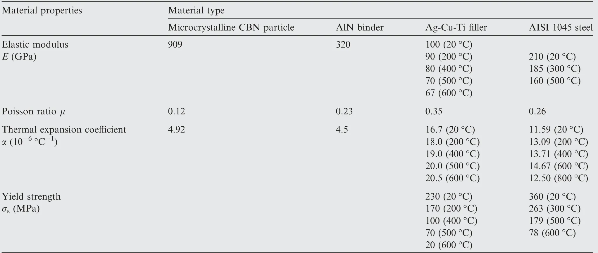
Table 1 Material properties used in FEA.
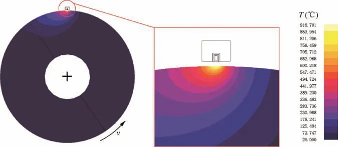
Fig. 2 Nonuniform temperature distribution in the induction heating zone.28

Fig. 3 Temperature variation curve of the core brazing zone.28
4. Results and discussion
4.1. Residual stress distribution characteristics of the brazed polycrystalline CBN grit
Fig. 4 Residual stress distributions of the whole grit and the stress concentration region during the cooling stage of a brazing process.
A polycrystalline CBN abrasive grit is a kind of typical brittle material, which can bear a high compressive stress but easily break under a high tensile stress.29Therefore, the maximum in-plane principal stress has been used to investigate the residual stress distribution. Other brazing parameters used in the simulation are as follows: the embedding depth is 40%, and the side length of the polycrystalline CBN grit is 200 μm.The residual stress distributions of the whole grit and the residual stress concentration region at different cooling temperatures of a typical core brazing zone are illustrated in Fig. 4,in which S means the stress of the grain, MPa. From the former three f igures,it is observed that the tensile stress is close to zero at the top of the polycrystalline CBN grit,increases gradually from top to bottom, and reaches the highest value (e.g.,430 MPa in Fig.4(d))until the grit bottom.With a decrease of the induction heating temperature,the residual stress distribution of the grit changes little,but the local stress concentration occurs more.The maximum compressive and tensile stresses of the whole grit at different temperatures are described in Fig.5.When the heating temperature of the filler alloy is below its melting point,residual stress will be produced in the polycrystalline CBN grit and the filler alloy. When the temperature reaches 600°C, the maximum tensile and compressive stresses are 241 and 50 MPa,respectively;as the temperature decreases to 400°C, the maximum tensile and compressive stresses increase to 355 and 73 MPa, with increases of 47.3% and 46.0%, respectively; when the temperature decreases to 200°C,the maximum tensile and compressive stresses increase to 414 and 90 MPa, with increases of 16.6% and 23.3% compared to those at 400°C, respectively.
In the polycrystalline CBN grit, the micro CBN particles are usually subjected to tensile stress, and the AlN binder is affected by compressive stress. Besides, because the thermal expansion coefficient of the filler alloy layer is larger than that of the polycrystalline CBN grit, the volume shrinkage of the filler alloy layer is obviously larger than that of the abrasive grit during the cooling process.Therefore, a high residual tensile stress has been produced among microcrystalline CBN particles as well as AlN binder and Ag-Cu-Ti alloy filler bonding interfaces. Moreover, concentrated tensile residual stresses are found in these interfaces.
4.2. Effect of the micro particle distribution on the induction brazing residual stress
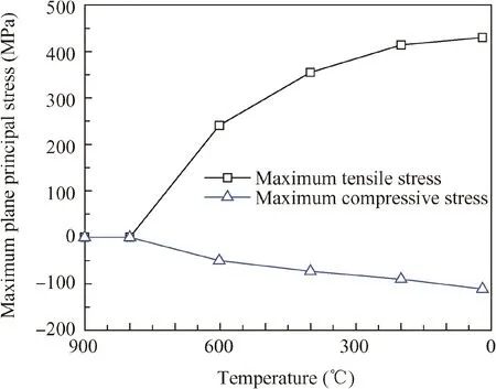
Fig. 5 Maximum residual stresses of the whole grit at different cooling temperatures.
The effect of particle non-uniformity on the residual stress distribution in induction brazing of the polycrystalline CBN grit has been investigated. Four different types of micro particle distributions are randomly generated using the Voronoi partition method. As illustrated in Fig. 6, the numbers of microcrystalline particles in these four polycrystalline CBN grits are 146,154,157,and 46,respectively.Among them,the numbers of microcrystalline particles in grits I, II, and III are approximately equal. The shapes, sizes, and distributions of the particles in the four grits are randomly generated,and each of them is different. The other parameters of the polycrystalline CBN grit models are as follows: the embedding depth is 40%and the grit side length is 100 μm.Thus,the simulation model of the particle distribution on the residual stress of a polycrystalline CBN grit is established.
Fig. 6 shows the residual stress contours of polycrystalline CBN grits after an induction brazing process. Obviously, the residual stress distributions of polycrystalline CBN grits are approximately the same under different crystallite particles distributions. The residual stresses on the top of polycrystalline CBN grits are relatively small, and some of them are close to zero. As the embedding depth becomes deeper, the residual tensile stress becomes higher.Meanwhile,a residual stress concentration appears on both sides and bottom of the grits. The maximum tensile stress of the four groups of polycrystalline CBN grits exists at the bottom, which is less than 500 MPa.The maximum compressive stress value is less than 114 MPa.Therefore, the shapes, sizes, and distributions of microcrystalline particles have less influence on the residual stress of a polycrystalline CBN grit, which can be therefore generally ignored in the simulation.
4.3.Inf luence of the grit side length on the brazing residual stress
The brazing residual stress distribution curves of polycrystalline CBN grits on Path I are demonstrated in Fig. 7. Geometric similarity is illustrated by the four curves in Fig. 7. It is obvious that the four curves show a similar tendency,which indicates that the grit side length does not affect the residual stress distribution on Path I. However, the grit side length has a great effect on the maximum tensile stress on Path I.As displayed in Fig. 7(b), when the grit side length is 100 μm, the maximum tensile stress on Path I is 347 MPa;when the grit side length is 200 μm,the maximum tensile stress on Path I reduces to 239 MPa, with a decrease of 31.1%.
The residual stress distribution curves on Path II with different grit sizes are shown in Fig.8.Maximum residual tensile stresses appear at both the bottom vertex and the bonding interface with the position of a 40% embedding depth. Maximum tensile residual stress curves with different grit sizes are illustrated in Fig. 8(b). When the grit size length is 50 μm,the maximum tensile stress is 361 MPa; as the grit side length increases to 100 μm, the maximum tensile stress increases to 430 MPa with an increase of 19%; when the grit side length increases to 150 and 200 μm, the maximum tensile stresses increase to 479 MPa and 575 MPa, with increases of 33%and 59% respectively compared with that of a grit side length of 50 μm. According to the reference, the tensile strength of polycrystalline CBN grits is 2.34 GPa, which is higher than 575 MPa.30Hence, a grain fracture will not occur under such a condition. Evidently, the maximum tensile stress increases with the value of the grit size. Based on the analysis above,it can be inferred that the larger the grit size is, the higher the maximum tensile stress is,which makes it easier to fracture during a grinding process.
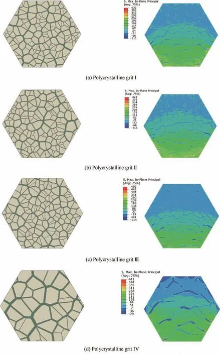
Fig. 6 Distributions of different crystallite particles and residual stress contours in high-frequency induction brazing.
4.4. Grain embedding depth effect on the residual stress
The residual stress distributions of polycrystalline CBN grits on Path I with different embedding depths are compared, as illustrated in Fig. 9. Among them, the grit side length in the simulation is 100 μm, and the embedding depth values are 20%,30%,40%,and 50%,respectively.It has been found that the embedding depth has signif icant effects on the residual stress distributions of polycrystalline CBN grits on Path I.On one hand,the residual stress of the grit with a 40%embedding depth is generally higher than those of the other three grits, and the residual stress curve of a 20% embedding depth is at the bottom. On the other hand, the residual stress curve with a 50% embedding depth is slightly higher than that with a 30%embedding depth,and both are very close.In addition,Mei et al. pointed out that brittle monocrystalline CBN grits could withstand a compressive stress up to 4.7 GPa and a tensile stress of 2.3 GPa without fracture.31Hence,a tensile stress usually plays a more signif icant role on particle damage than a compressive stress, which makes the brittle fracture of a grit happen easier under a tensile stress. Therefore, the maximum tensile stress in a polycrystalline CBN grit is discussed in simulation analysis.
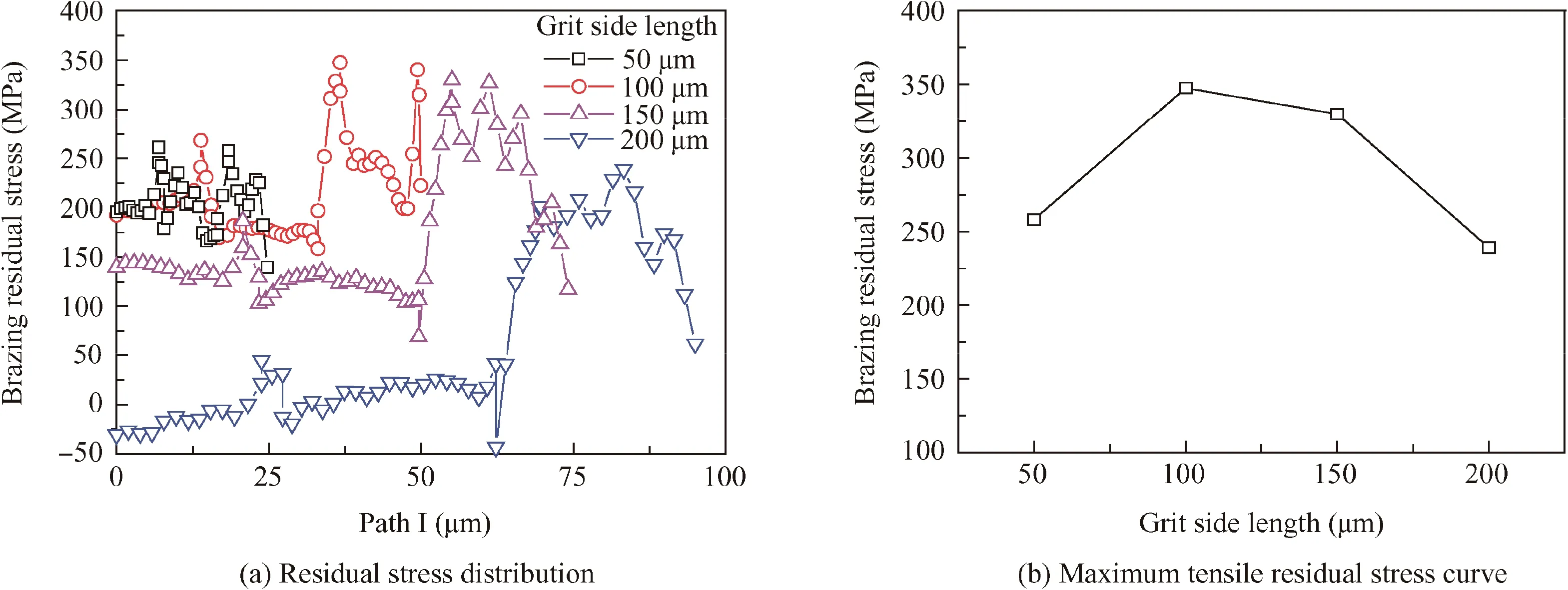
Fig. 7 Brazing residual stress distributions on Path I with different grit sizes.
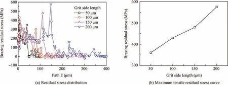
Fig. 8 Residual stress distributions on Path II with different grit sizes.
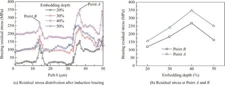
Fig. 9 Residual stress distributions on Path I with different embedding depths.
As displayed in Fig.9(a),a local stress concentration occurs at Point A and B(both on Path I).The residual stress curves of Points A and B under different embedding depths are shown in Fig. 9(b). Obviously, the peak values of the residual stresses always occur at Points A and B,and the values of tensile stresses increase when the embedding depth increases from 20%to 40%, and decrease when the embedding depth comes to 50%.At Point A, the tensile stress is 112 MPa when the embedding depth is 20%. With the embedding depth increasing by 40%,the tensile stress at Point A increases to 268 MPa, and the stress increases by 148 MPa with an increase of 123.7%. With the embedding depth increasing to 50%, the tensile stress is reduced to 163 MPa,with a decrease of 39.3%compared with that of a 40% embedding depth.
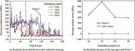
Fig. 10 Residual stress distributions on Path II at different embedding depths.
Fig. 10 shows the residual stress distributions of polycrystalline CBN grits on Path II at different embedding depths.The induced tensile stress on Path II is very signif icant, while the compressive stress is relatively small, and the maximum compressive stress is less than 15 MPa. Due to the large thermal expansion coefficient of the Ag-Cu-Ti filler alloy, in the cooling stage, the polycrystalline CBN grit is stretched by the filler layer,which results in a high tensile stress on the first half of Path II. However, the residual stress becomes much smaller on the latter half of Path II, and reaches to zero at the end of Path II.Moreover,the stress curves on Path II f luctuate frequently, and the tensile stress values vary greatly.Owing to the large number of microcrystalline particles located on the first half of Path II, the AlN binders extend to the periphery of the polycrystalline CBN abrasive grit.Meanwhile,the thermal expansion coefficient of microcrystalline particles is much smaller than those of both AlN binders and the Ag-Cu-Ti filler alloy, high tensile stresses are therefore formed in the microcrystalline particles. On the latter half of Path II,the microcrystalline particles are only affected by the binders.The tensile stresses become much lower without direct influences of the Ag-Cu-Ti filler alloy, and are even close to zero near the end of Path II.
Point C in Fig. 10(a) is on the highest position of the filler metal.It is noticed that the tensile stress increases signif icantly at Point C,where the maximum tensile stress occurs.As shown in Fig.10(b),the stress values at Point C and in the top region under different embedding depths are presented. When the embedding depth is 20%, the tensile stress at Point C is 347 MPa.When it increases to 30%,the tensile stress at Point C reaches the maximum,which is 584 MPa,with an increase of 68.1%.When the embedding depth increases to 40%and 50%,the tensile stresses are 292 MPa and 301 MPa, respectively,and both values are very close. Compared with the 30%embedding depth, the tensile stresses with 40% and 50%embedding depths decrease by 50% and 48.5%, respectively.Besides, residual stresses at the top vertex are not affected by the embedding depth, and are all close to zero.
According to the discussion above, it can be observed that there are a lot of stress concentrations on the three paths of polycrystalline CBN grits,and the stress distributions on Path II are most complex, which has an important impact on the micro fracture and wear of polycrystalline CBN grits.Furthermore, compared with other embedding depths, 40% and 50%embedding depths can make the maximum tensile stress of a grit on Path II be the lowest. On the other hand, the 40%embedding depth is conducive to the promotion of chip space without reducing the holding force for grits.32Therefore, the 40% embedding depth is chosen as the optimum.
5. Experimental verif ication of simulation results
For monocrystalline CBN grits, the ref lection peak of CBN can be measured by a Raman spectrometer Jobin Yvon HR800UV (Fig. 11). The stress values of specific points in the monocrystalline CBN particles can be calculated according to the offset of the peak value, and the calculation formula of the stress value and the peak shift is as follows26:
where p is the proportionality constant of CBN,whose value is 4.5 cm-1/GPa;wjis the actual spectrum peak of CBN;w0is the characteristic spectrum of CBN, whose value is 1055 cm-1.33
It is necessary to point out that a measurement of the internal stress in a polycrystalline CBN grit is still very difficult,and the accuracy cannot meet the test requirements.Therefore,the simulation results are verif ied indirectly in this work:the residual stress of monocrystalline CBN grit simulation and experiment is carried out, which determines the accuracy of induction brazing monocrystalline CBN grit simulation results. Then, the simulation results of both the monocrystalline CBN grit and the polycrystalline CBN grit are compared. Based on the stress distributions of the monocrystalline CBN grit and the polycrystalline CBN grit,the induced residual stress of the polycrystalline CBN abrasive grit is verif ied indirectly.

Fig. 11 Laser micro Raman spectrometer.
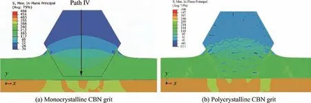
Fig. 12 Residual stress contours in simulations.
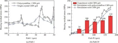
Fig.13 Comparison of the residual stress distribution between CBN and polycrystalline CBN grits as well as experimental verif ication of the residual stress of the monocrystalline CBN grit.
Fig.12 shows the residual stress contours of the monocrystalline CBN grit and the polycrystalline CBN grit after induction brazing. Among them, the sizes of monocrystalline and polycrystalline CBN grits are both 200 μm,and the embedding depths are 40%. On the whole, the residual stress distribution of the monocrystalline CBN grit is symmetrical. The tensile stress is close to zero at the top of the grit,and becomes higher when it is closer to the bottom. Moreover, a stress concentration in the bonding part between the abrasive grit and the filler alloy occurs at the embedded part of the grit. Compared with the stress contours of the polycrystalline CBN grit, the stress distributions of the two results are similar, and the values of the maximum tensile and compressive stresses are basically the same.
The stress distribution curves of monocrystalline and polycrystalline CBN grits on different paths are compared in Fig.13.Fig.13(a)shows the stress distribution on Path I,which is located at the bottom of the abrasive grits.The stress distributions of both monocrystalline and polycrystalline CBN grits are similar.Meanwhile,it is noticed that the stress curve of the monocrystalline CBN grit is relatively smooth,while that of the polycrystalline CBN grit has three sharp peaks. The reason is that these three peaks are located at the junction of the microcrystalline particles and the AlN binder of the polycrystalline CBN grit, where the residual stress is concentrated. Fig. 13(b)shows the stress distribution on Path IV. Path IV starts at the midpoint of the top edge, and terminates at the midpoint of the bottom edge(Fig.12(a)).It is observed that the stress values of both monocrystalline and polycrystalline CBN grits are nearly zero, and become higher when reaching the bottoms of the grits. Meanwhile, a verif ication of the residual stress of the monocrystalline CBN grit is carried out, and the stresses along Path IV are measured by a Raman spectrometer.Results of the experiment are shown in Fig.13(b).Based on the analysis, the induced residual stress distributions of the polycrystalline CBN grit are verif ied indirectly.
6. Conclusions
A stress simulation model of high-frequency induction brazing polycrystalline CBN abrasive grits is established,and the residual stress distributions of polycrystalline CBN grits are analyzed. Conclusions are summarized as follows:
(1) Compared with other embedding depths, the tensile stress with a 40% embedding depth is 292 MPa, which is the minimum on the bonding interface.
(2) When the grit side length changes, the maximum tensile stresses is 575 MPa, with an increase of 59% compared with that of a grit side length of 50 mm,which indicates that a longer grit side length makes fracture occur more easily.
(3) The simulation results of the brazing residual stress of polycrystalline CBN abrasive grits have been verif ied true through an experimental measurement of the residual stress distribution in the brazed monocrystalline CBN grits.
Acknowledgements
This work was f inancially supported by the National Natural Science Foundation of China (No. 51775275) and the Fundamental Research Funds for the Central Universities (No.NE2014103 and No. NZ2016107).
杂志排行

CHINESE JOURNAL OF AERONAUTICS的其它文章
- Guide for Authors
- CHINESE JOURNAL OF AERONAUTICS
- An automated approach to calculating the maximum diameters of multiple cutters and their paths for sectional milling of centrifugal impellers on a 4½-axis CNC machine
- Online scheduling of image satellites based on neural networks and deep reinforcement learning
- An evolutionary computational framework for capacity-safety trade-oあin an air transportation network
- Satellite group autonomous operation mechanism and planning algorithm for marine target surveillance