Performance Optimization of Microstrip Antenna with Different Slot Configurations and Various Dielectric Materials
2018-12-26SoumenduGhoshAbhijitGhoshlndranathSarkar
Soumendu Ghosh* | Abhijit Ghosh | lndranath Sarkar
Abstract—The probe-fed patch antennas were proposed by changing the parameters such as dielectric materials and dimensions of patch for detail investigation of changes in output characteristics.Four rectangular slots were introduced separately for optimizing the antenna design and characteristics.This study illustrated the changes of output characteristics of an antenna with respect to the number of introduced slots on the radiating patch in addition to the effect of various dielectric materials on antenna performances.The antenna performances were analyzed by plotting the observation of various dielectric materials.The changes of antenna characteristics were also observed by introducing four numbers of slots on each edge of the patch to improve radiation characteristics with a wider impedance bandwidth.
1. lntroduction
Wireless communications[1]are the most emerging and attractive technology in the present generation.This wireless communications depend upon the radiation.The high-performance miniature antenna is required to provide a good radiation[2]performance for various communications systems like wireless local area network(WLAN)[3], worldwide interoperability for microwave access (WiMAX)[3], wireless fidelity (Wi-Fi)[4], satellite communications[5], and global positioning system (GPS)[6].The research and development on compact[7]highperformance antenna are increasing day by day.The conventional metallic antennas have some major problems,such as low gain, high power requirement, narrow bandwidth, big in size, poor radiation characteristics, lack of design flexibility, and fabrication problems.These problems can be eliminated by using the compact microstrip antennas.
The rectangular microstrip patch antenna[8],[9]has been tested with two degrees of freedom, the slot configuration on the patch and the dielectric constant.These two additional degrees of freedom give more flexibility to the experiment of patch antenna in the field of the resonant frequency of the excited modes.Taking these results a step further, the antennas with following specifications are numerically tested.
2. Antenna Structure
In this paper, we have simulated and analyzed the output characteristics of five different rectangular antenna structures with the variations of dielectric materials.The length, width, and feed position of all radiating patches are identical for all microstrip antennas.The five single layer microstrip patch antennas are shown in Fig.1 with length A=40 mm, width B=30 mm, and substrate thickness h=3.2 mm.A coaxial probe-feed[10],[11]is used to excite the patch of microstrip antenna.Fig.2 shows the thickness and feed position.

Fig.1.Diagrams of single layer microstrip patch antennas: (a) simple radiating patch antenna, (b) simple radiating patch with L1 slot, (c) simple radiating patch with L1 & L2 slots, (d) simple radiating patch with L1, L2, & L3 slots, and (e) simple radiating patch with L1, L2, L3, & L4 slots.

Fig.2.Thickness and feed position of antennas.
The geometric dimensions of different parameters for the proposed antennas are shown in Table 1.These antennas are optimized after the continuous simulation work.The most important parameters are the numbers of etched slots[12],[13]on the edges of the radiating patch.
3. Results and Discussion
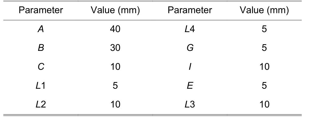
Table 1: Specification of simulated antennas
All the antenna structures are simulated by using ANSYS HFSS[14].Five antenna structures have been simulated and compared by varying the dielectric material.Four dielectric materials were used in all the simulations, including FR4_Epoxy, Mica, Rogers RT/Duroid 5880, and Teflon.
1) Simple radiating patch antenna
The S11 parameters of simple patch antennas (without slot) for four different dielectric materials are shown in Fig.3 .The results illustrated that the –10 dB impedance bandwidths for the antennas with FR4_Epoxy, Mica,Rogers RT/Duroid 5880, and Teflon dielectric are 950 MHz (9.74 GHz to 10.69 GHz), 1710 MHz(4.80 GHz to 6.51 GHz), 380 MHz (7.84 GHz to 8.22 GHz), and 285 MHz (7.080 GHz to 7.365 GHz),respectively.It also has been observed that the FR4_Epoxy and Rogers RT/Duroid 5880 antennas show two resonant frequencies while Mica and Teflon antennas provide three different resonant frequencies.
2) Antennas with single slotted rectangular radiating patch
Fig.4 shows the S11 parameters of the single slotted patch antennas for four different dielectric materials.The –10 dB impedance bandwidths for the antennas with FR4_Epoxy, Mica, Rogers RT/Duroid 5880, and Teflon dielectric are 1045 MHz (4.230 GHz to 5.275 GHz), 1710 MHz (5.085 GHz to 6.795 GHz),475 MHz (6.605 GHz to 7.080 GHz), and 475 MHz(6.795 GHz to 7.270 GHz), respectively.The antennas with FR4_Epoxy, Mica, and Teflon provide 3 different resonant frequencies.But that of Rogers RT/Duroid 5880 only shows one single resonant frequency.
3) Antennas with dual slotted rectangular radiating patch
The S11 parameters of the dual slotted patch antennas for 4 different dielectric materials are also simulated, respectively, as shown in Fig.5.The –10 dB impedance bandwidths of 1140 MHz (4.04 GHz to 5.18 GHz), 2090 MHz (5.37 GHz to 6.46 GHz), 380 MHz(6.70 GHz to 7.08 GHz), and 380 MHz (6.89 GHz to 7.27 GHz) for the antennas with FR4_Epoxy, Mica,Rogers RT/Duroid 5880, and Teflon dielectric are obtained, respectively.The FR4_Epoxy one provides three different resonant frequencies.It has been depicted that the resonant frequency changes with the variations of the dielectric materials at the same antenna geometry.
4) Antennas with triple slotted rectangular radiating patch
Fig.6 depicts the S11 parameters of the triple slotted patch antenna for 4 different dielectric materials.The–10 dB impedance bandwidth is 1330 MHz (9.455 GHz to 10.785 GHz) for the antenna with FR4_Epoxy,1615 MHz (4.990 GHz to 6.605 GHz) for that of Mica, 380 MHz (6.70 GHz to 7.08 GHz) for Rogers RT/Duroid 5880, and 380 MHz (6.89 GHz to 7.27 GHz) for Teflon.It also shows that the Rogers RT/Duroid 5880 dielectric antenna resonates at the frequency of 1 GHz and all the 4 dielectric antennas provide more than one resonant frequency.
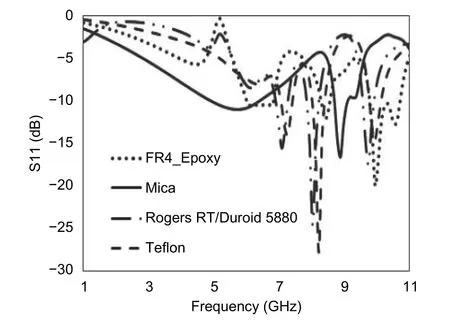
Fig.3.Simulated results for simple patch antenna (without slot).
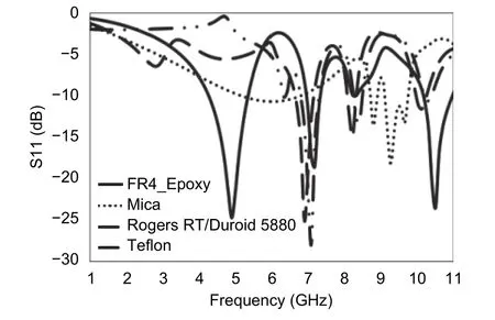
Fig.4.Simulated results for single slotted patch antennas.
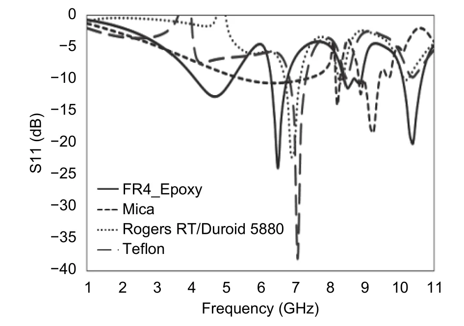
Fig.5.Simulated results for dual slotted patch antennas.
5) Antennas with quad slotted rectangular radiating patch
The S11 parameters of quad slotted patch antennas for 4 different dielectric materials are shown in Fig.7.The–10 dB impedance bandwidths for the antennas with FR4_Epoxy, Mica, Rogers RT/Duroid 5880, and Teflon dielectric are 1045 MHz (4.040 GHz to 5.085 GHz), 1140 MHz (6.605 GHz to 7.745 GHz), 285 MHz (6.795 GHz to 7.080 GHz), and 380 MHz (6.89 GHz to 7.27 GHz), respectively.Multiple resonant frequencies have been observed for all the 4 dielectric antennas with the same antenna dimension.It has also been studied that both Teflon and Rogers RT/Duroid 5880 antennas resonate at 1 GHz.
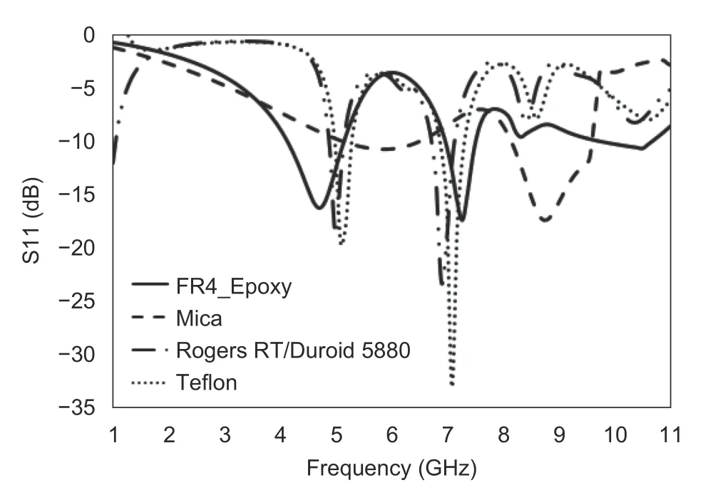
Fig.6.Simulated results for triple slotted patch antennas.
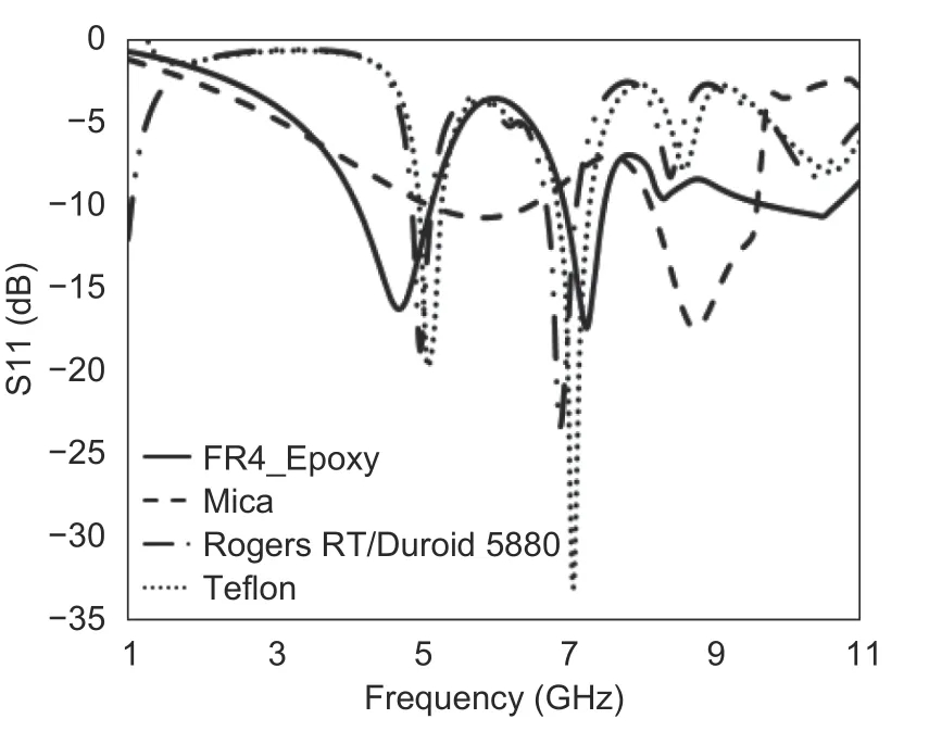
Fig.7.Simulated results for quad slotted patch antennas.
Obviously, the above observation shows that the slot and the dielectric material between the ground plane and patch do have an effect on the impedance bandwidth and resonant frequency.All of the proposed dielectric material antennas with different slot configurations can provide an excellent performance.Table 2 provides the gain performances of all simulated antennas.

Table 2: Simulated gain of antennas
It has been observed that the gain and bandwidth change significantly with respect to the slot and dielectric material.The path of the excited current of the patch changes the gain and bandwidth of these antennas with the increase of the number of the slots.Various slot configurations have been used in the antenna simulation for observing the results of antenna characteristics with the changed slot configurations.The analysis of all 5 antennas have been also observed with the variations of dielectric constant (relative permittivity) from 2.1 to 5.7.The antenna performance changes significantly with the antenna dielectric.
It also has been observed that all antennas provide an excellent gain performance.The triple slotted Fr4_epoxy antenna provides the highest gain among all FR4_Eproxy antennas.The quad slotted Mica antenna provides the highest gain among all Mica antennas.The single slotted Rogers RT/Duroid 5880 antenna shows a higher gain compared with other Rogers RT/Duroid 5880 antennas.The Teflon antenna also can provide a high gain.It has been analyzed that the gain of antenna changes with the slot configuration and the dielectric material.
4. Future Scope
This research work has analyzed various compact microstrip antennas.Future work can be carried out for the development of various microstrip antennas on the various dielectric materials to obtain a wider bandwidth[9]and a higher gain for high-quality wireless communications link.Moreover, non-conventional dielectric material antenna will be useful for future wireless communications devices[15],[16].
5. Conclusion
It is a truth universally acknowledged that microstrip patch antenna is mainly useful for wireless communications devices.But its application is limited owing to the microstrip antenna's disadvantages like low gain, small bandwidth,etc.In this paper, we found that the gain and bandwidth are highly related with the dielectric material and the slot configuration of the antenna.It also has been observed that some of the low-cost non-conventional dielectric materials,like Mica dielectric antenna, Teflon dielectric antenna, can achieve a high gain with a wider bandwidth.
杂志排行
Journal of Electronic Science and Technology的其它文章
- Guest Editorial____________________________Special lssue on Energy-Efficient Technologies—Crowd Energy Applications
- lntegrating Smart Building Energy Data into Smart Grid Applications in the lntelligent Secondary Substations
- Energy-Efficient Operation of Water Systems through Optimization of Load Power Reduction in Electricity Markets
- Options and Opportunities for Energy Management in Malaysian Grid Systems—Putrajaya as a Case Study
- lmplementation of Efficient B2G and V2G in Practical Cases
- lnvestigating Energy Prosumer Behaviour in Crowd Energy Using an lnteractive Model/Diorama
