lntegrating Smart Building Energy Data into Smart Grid Applications in the lntelligent Secondary Substations
2018-12-26StephanCejkaKonradDiwoldAlbinFrischenschlagerPhilippLehninger
Stephan Cejka* | Konrad Diwold | Albin Frischenschlager | Philipp Lehninger
Abstract—Automation has arrived in the low voltage grid domain.In the next few years, the secondary substation—at the barriers of medium and low voltage grids—will thus be upgraded to enable novel functions.In this paper, we present various smart grid applications running on such intelligent secondary substations (iSSN) including their interaction with each other.We integrate energy consumption and production data, as well as forecasts, sensed from the smart buildings’ energy management systems (BEMSs) into the operation of the low voltage grid.A suitable framework for those modular applications includes features to initiate their installation, update, removal, the remote operator site, and not requiring staff on-site for such typical reappearing maintenance tasks.
1. lntroduction
The ongoing automation progress in various domains can also be observed in low voltage (LV) grids.Power grid devices such as smart meters, smart breakers, or smart storage systems show an Internet of Things (IoT)transition in the grid itself as they evolve into communicating and interacting elements[1],[2].Furthermore, the number of active components, such as photovoltaic, battery, or home automation systems, has steadily been increased over the last years.Industrial research in automating low voltage grids is ongoing, products are in active development[3],[4], and smart buildings are increasingly integrated into the LV grid operation[5].
This transition in the power grid includes the domain of secondary substations located on the barriers between the medium and low voltage grids.They are isolated devices concerning communications; thus any interaction requires staff on-site[6].By utilizing modern information and communications technology (ICT), they can evolve into intelligent secondary substations (iSSN) by having newly attained communications abilities and improved communications power.This evolution allows for a wide range of novel applications for an increase of efficiency and better use of the grid infrastructure, to save on investments and increase the grid’s reliability.
In previous work, we have presented a flexible and modular software ecosystem for iSSN that allows for the operation of distributed smart grid applications[6],[7].Novel functions can be realized by distributed modular software components—so-called smart grid applications—of which many have already been developed using this framework[7]-[9].As only the distribution system operator (DSO) for Vienna and surrounding areas operated 10.718 secondary substations in 2014[10], it is evident that each operator may be responsible for vast amounts of such substations.Thus, a primary requirement for the upgrade to iSSN is cost efficiency.
DSOs can benefit from integrating sensed energy consumption from smart buildings’ energy management systems (BEMSs)[5].Equipped with a photovoltaic site can produce own energy—such an entity that both consumes and produces energy can thus be termed as a “prosumer”.The grid operation can be even more improved when using forecasts of the buildings, for example by predicting the near future energy consumption using weather forecasts.
The remainder of this paper is structured as follows: Section 2 describes the iSSN application framework consisting of the middleware gridlink, on which all applications are built and by which the applications communicate.It further shows the integrated provisioning features to allow typical maintenance tasks to be issued by the remote operator.Various smart grid applications running on this framework are described in Section 3,including their interaction with each other.Section 4 concludes the paper with a summary and outlook on possible future work.
2. iSSN Application Frame
In previous work[6],[7],[9],[11], we have introduced a software ecosystem for the iSSN allowing the concurrent execution of modular software applications communicating over a proprietary middleware.This middleware needs to fulfill modularity, resilience, scalability requirements to ensure a smooth integration of applications and the functional extendability while keeping influences of one application on others on a minimum level (plug and automate paradigm)[11].Furthermore, it provides a mechanism for the automatic deployment of applications from the remote operator site without any on-site engineering.Fig. 1 shows this software ecosystem, including a data storage and an App manager module for provisioning features[7].Sophisticated functions and services can be developed that make use of the ICT-connected power grid components and external services (e.g., forecasting and weather information).This section is concluded with node management to allow executing modular applications in a memory efficient way and raised security threats.
2.1. Gridlink
The Gridlink[6],[7]is a Java-based middleware allowing distributed communications in smart grid use cases using an asynchronous communications model.Its primary requirement is to provide a resilient and scalable middleware to connect several autonomous modular smart grid applications—called module.Gridlink unlike many typical IoT middleware solutions[12]is a distributed middleware with the benefit of not creating a singlepoint-failure within the system.Modules run within a Java virtual machine (JVM), termed the nodes dynamically form a cluster of known instances during execution.They can join or leave at any time without influencing other modules’ execution or communications.Communications with the components outside of a Gridlink system are achieved by using gateway modules, for example, to receive measurements using IEC 60870-5-104 protocol transmission.
2.1.1. Message Exchange
Gridlink modules communicate with each other by exchanging messages.They first register themselves for roles or topics, in which they are interested in receiving messages.Such a role provides handlers for serving one or more services and can thus be seen as a container grouping related services.Fig.2 shows the relationship between those three terms[6].A storage module is registered for the roles storage and shutdown.The role storage provides several services (e.g., create data point).
Messages are identified by a type (e.g., create data point), contain a destination role address (e.g., storage),and may optionally include a payload (e.g., the data point to be created).They are either sent to a designated module role address or published to a topic address reaching all registered modules.Before a message is transmitted, it can be modified using configured proxies (see Fig.3[7]) to do additional message processing steps, including the modification of a message (e.g., for encryption).Respective proxies are executed at the message’s recipient.Afterward, the registered service handler for the received message type is called to process the message, which optionally includes issuing a reply message.
The operator configures the proxies in use; thus they stay entirely transparent for the sender and receiver modules.Multiple proxies can be executed in sequence(cf.Fig.3), as defined in the module’s configuration, and proxies can even be plugged in and out during the runtime of the affected module.
2.1.2. Registry
The Gridlink registry is a distributed list of all currently attached and active modules, as well as the roles/topics they are registered to.It furthermore contains the list of messages (i.e., service handlers) that the according role/topic can handle.All modules have access to the registry, such that each module has knowledge that which modules are present at any time.
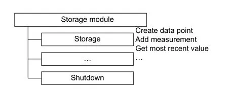
Fig.2.Modules, roles, and services.
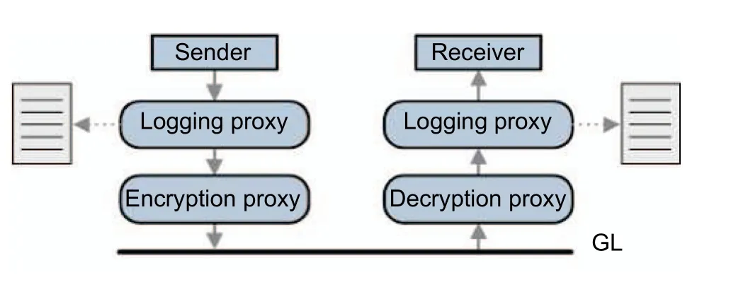
Fig.3.Example utilizing the Gridlink proxy concept for logging and encryption of message payloads.
2.2. Remote Provisioning
When operating thousands of iSSN, a significant requirement is to roll out software applications without requiring staff on-site.The installation of new features, update, and reconfiguration, as well as their removal,are typical software maintenance tasks grouped under the term “provisioning tasks”.In the introduced iSSN application frame, a designated Gridlink core module, the App manager[6],[7], is responsible for handling and executing those tasks on the iSSN.It receives commands and downloads software artifacts via its extensible messaging and presence protocol(XMPP) connection to the operator (see Fig.4[11]); and installs, updates, configures, and stops the managed Gridlink module operator’s dashboard,communicated to and executed by the local App manager module.Status information is communicated back to the operator.
In an early demonstration use case[6], the detection and handling of voltage band violations have been shown.This demonstration consists of seven modules running on one host machine in the iSSN (see Fig.5)[6].
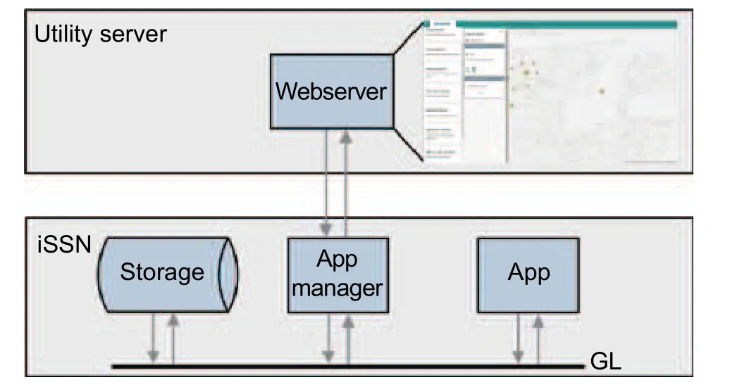
Fig.4.Provisioning tasks are initiated from the remote site.

Fig.5.iSSN use case scenario.
Initially, all depicted modules except the voltage guard are installed and running.The simple data generator module simulates the consumption of four apartment houses—some of them require additional loads at a certain time of the day and some of them are also equipped with attached photovoltaic production.The resulting voltage values (shown in Fig.6)[6]are transmitted to and stored in a storage module, such that other(i.e., analysis) modules can use historical and current values.

Fig.6.Voltage curves before installation of voltage guard.
The demonstration furthermore shows the provisioning of modules where the installation is initiated by the remote operator and executed on the device.During the day, a voltage level violation (cf.Fig.6) is detected by the voltage problem handler module and communicated to the operator by the use of a web dashboard.As a countermeasure to the voltage band violations, the operator decides to install the voltage guard module during the runtime of the other modules.This module analyzes the voltage measurement values in the grid and reacts when approaching the voltage band limits.Active voltage regulation measures are achieved by utilizing an on-load-tapchanger (OLTC) transformer[13].On detecting violations of the defined voltage band, it issues messages to the OLTC controller to change the tap position of the transformer, resulting in an increase of the voltage level by 2.5 V on tap up and a decrease on tap down, respectively.Thus, due to the voltage guard’s installation, the values all remain within the allowed voltage band (see Fig.7)[6].
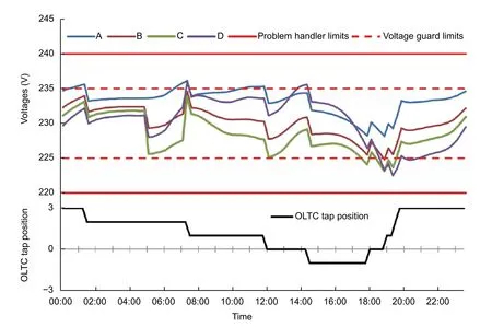
Fig.7.Voltage curves and OLTC tap position with the voltage guard installed.
2.3. Node Management
The need for modular applications requires running a high number of various modules for small independent tasks simultaneously.In the use case, all interlinked Java applications run on one automation component, an industry grade for specific amounts of computation and memory resources.Previously, one Gridlink node (i.e., one JVM) executed precisely one module started either manually by the user itself or by the App manager module.This approach, however, introduces high overhead regarding the main memory consumption as most of the memory consumption of a module originates from JVM caused overhead and loaded libraries (shown as the blue part of the module’s memory consumption in Fig.8)[11].In consequence,the number of required modules for a typical smart grid use case is typically higher than the random access memory (RAM)-constrained devices which can host simultaneously.Thus, the desired modularity of iSSN applications’ modules clashes with limited computation resources available.
Due to the high memory usage of multiple modules running each on its own JVM instance, we introduced a new entity—the node manager module[11], which can dynamically load smart grid applications within one JVM.It manages multiple other Gridlink modules within its JVM even though these modules may be installed, updated,and uninstalled during the runtime of the node and other modules.As the solution requires JVM libraries and Gridlink dependencies to be loaded only once, it reduces the memory usage by a massive extent.
To show the impact of the new solution, we conducted experiments using the introduced demonstration use case, resulting in a significant reduction for the seven modules from 800 MB to 200 MB in Fig.5[11].The memory consumption for n modules with their memory consumption for additional required libraries, their logic,and their data structures miand (for simplification assumed) a constant amount of Gridlink dependencies’memory consumption c was thus reduced from
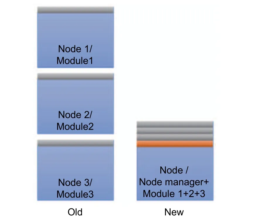
Fig.8.Compared memory consumption of the old solution (one module per node/JVM) and the new solution(a node manager on one node/JVM with multiple managed modules).The memory consumption of the JVM is shown in blue.

to

2.4. Security Threats
Potential attack patterns can be distinguished in the ones mainly originating from the communications aspects and the ones mainly originating from the framework itself.
2.4.1. Gridlink Communications Security Threats
Threats related to communications partly originate from the fact that vert.x as the Gridlink’s underlying communications framework does not differ between roles and topics, and thus every role can be claimed by more than one module.Messages published to a topic are delivered to all of the registered modules, while the behavior of vert.x in case of sending messages to a role is to deliver it to the respective modules in a round-robin fashion.
· A malicious module could thus register to a role address and deny the correct execution of message exchange as the intended module would now receive only a part of the messages (role claim attack).
· If the malicious module registers itself to a topic address, all messages would still be received at the intended module.However, the malicious module receives the same messages and is thus able to observe the communications (topic claim attack).
· A malicious module, located on the sender side, could issue messages appearing to originate from a permitted module, such that the receiver would not be able to tell right and evil messages apart (spoofing attack).
2.4.2. Gridlink Framework Security Threats
· vert.x uses a shared event bus thread for all modules on one node.When using node management, one malicious module could affect or even block all others on that node (event bus blocking attack).
· The Gridlink registry is a central extension to vert.x; all Gridlink modules are listed there.While vert.x“verticles” would be able to communicate with the Gridlink modules they will not appear there (invisible module attack).
2.4.3. Gridlink Security Layer
The Gridlink security layer utilizes the Gridlink proxy concept (cf.Fig.3) and thus does not introduce new components.Using Gridlink proxies at the sender and recipient sides for encryption/decryption of messages denies that malicious modules can read the communications.For the role claim attack, it needs to be noted that this procedure cannot ensure that all messages are received at the correct module due to the mentioned round-robin delivery.
As third-party modules are already in development, it needs to be ensured to deny malicious communications.Further proxies filter prohibited messages to and from such modules based on their message type & sender and message type & receiver, respectively.As all proxies are defined by the module’s user (i.e., the operator) and not by its developer, the mechanism allows specifying the allowed communications of a module without requiring in-depth inspection of the third-party module.As a countermeasure to the invisible module attack, a proxy could be used to let pass messages issued by a module listed in the registry only.
Proxies can, however, not help with the event bus blocking attack.We have introduced the concept of the trusted Gridlink Apps[14]allowing the certification of modules.Thus, execution of uncertified/untrusted modules beside trusted ones on the same physical node can be prohibited.For improved availability, modules with higher processor consumption, modules expected to reply fast, as well as “fundamental” modules should be moved to their own node; thus, not requiring sharing the event bus with other modules.
3. Applications in the iSSN
With remote provisioning features and the node manager extension, the Gridlink system is suitable for modular applications plugged in (installed/started) and out (stopped/uninstalled) during the runtime (plug and automate paradigm) and the concurrent execution of a high number of modules on one node.For presenting provisioning and node management, it was reasonable to utilize the simple use case in Fig.5.In publications that focus more on module functions rather than on the framework itself, we have introduced more sophisticated modules to enable novel functions on the power distribution grid level, e.g., for data processing, analysis, and grid operation[7]-[9].Those modules can be grouped into data acquisition modules (subsection 3.2), modules for data preprocessing,representation, and retrieval (subsection 3.3), and data analysis and actor modules (subsection 3.4).All modules involved in the use cases are shown in Fig.9.Data in the use case originates from smart meters or sensors in the field or stems from the BEMS.The data approaching the Gridlink system via one of the gateway modules is subsequently persisted in the storage module and may then be accessed by all other modules in the system.Fig.10 shows a simplified data flow between modules discussed in the following subsections.

Fig.9.Involved Gridlink modules.For this figure it is assumed that all modules are running within one node.
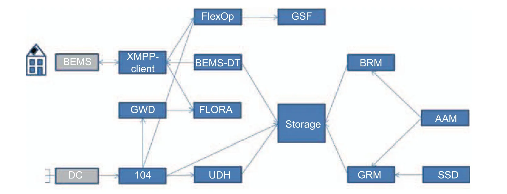
Fig.10.Simplified data flow of the involved Gridlink modules.
3.1. Core Modules
Two of the modules, namely the App manager and the node manager, have already been described when presenting the framework, thus they are termed as core modules.
3.1.1. App ManagerThe App manager module[6],[7]is responsible for executing provisioning tasks on the iSSN received from the operator on the remote uplink (cf.subsection 2.2).
3.1.2. Node Manager
The node manager module[11]is responsible for managing various modules in execution on one node and thus in one JVM for achieving memory efficiency (cf.subsection 2.3).
3.2. Data Acquisition Modules
The modules that are listed in this section are responsible for acquiring data from smart buildings and the power grid.Some of them are connected to the components outside of the Gridlink system (e.g., the BEMS), which makes them so-called gateway modules.
3.2.1. XMPP-Client
The generic XMPP-client module is the gateway to the smart building used to gain energy data and forecasts to be used within the use case.It is thus connected via an XMPP connection (over an XMPP server) to the BEMS.Modules need to specify which data they require from the BEMS for the use of the generic XMPP-client.The use of XMPP for connections between the grid and buildings has been previously tested[15].
3.2.2. BEMS-Data Translator (BEMS-DT)
Within a smart building, the BEMS optimizes the power consumption aiming at cost minimization taking the forecasted generation, available storage capacities, flexible pricing, and the user behavior into consideration.This data translator module requests and translates measurements and other data required to be persisted in the iSSN(using the storage module) from the XMPP message format to Gridlink message types.
3.2.3. 104-Stack
Comparable to the XMPP connection to smart buildings, this module provides the connection to the LV grid’s data concentrator for grid measurement values.It thus translates incoming measurements from IEC 60870-5-104 protocol format[16]to the proper Gridlink message types.
3.2.4. Unavailable Data Handler (UDH)
To enhance data quality, unavailable data of temporarily unavailable sensors in the grid needs to be substituted[8].Suitable topology-based and history-based algorithms for substituting voltage measurements have been analyzed[17](e.g., Kriging, k-nearest neighbor regression).
3.3. Data Storage and Representation Modules
After the acquisition of data, it necessarily needs to be persisted for further use.While for some usages, current data might be sufficient, some analysis modules will also require access to historical data.More complex data representations (e.g., topologies) cannot easily be provided by the storage module and thus require proper representation modules; the representation itself, however, gets updated by the storage.
3.3.1. Storage
For most modules, it is vital to have access to historical and current measurement data.The storage module[7]is used for the permanent storage of the accumulated data and makes these data available to other modules.Data in our use cases is usually time-series of sensor data (e.g., voltage values) and metadata of the attached data point(e.g., sensor type and location).Therefore, the storage module utilizes a proprietary Java-based embedded data store, shown to be superior to state-of-the-art off-the-shelf structured query language (SQL) and not only structured query language (NoSQL) solutions concerning the data retrieval time and the required storage size[18].Characteristic data requirements in smart grid applications such as large volumes of data, small immutable data records, and frequent readouts as well as the generation of statistical indicators are optimally supported.
3.3.2. Building Representation Module
The building representation module (BRM)[7],[9]represents smart buildings connected to the distribution grid.It collects and preprocesses data and provides it to other modules.During preprocessing, data gaps are identified and seamless time-series are created.
3.3.3. Grid Representation Module
The grid representation module (GRM)[7],[9]represents the distribution grid with its topology and components(e.g., lines and switches) utilizing an adjacency matrix.Similar to the BRM, it collects and preprocesses data and provides it to other modules.
3.4. Data Analysis and Actor Modules
To gain knowledge of the current grid, to make predictions of near future grid states, and to act accordingly,data analysis and actor modules have been developed.
3.4.1. Grid Watch Dog
The grid watch dog (GWD)[8]is used to monitor the grid (e.g., voltage, current, and voltage asymmetry) and is thus an extension to the simple voltage problem handler module of the introductory example.The GWD’s core is a data stream reasoner that allows to reason on instantaneous as well as on integrated and averaged grid measurements.It consists of rules in declarative logic, which can be combined with logical operators to allow even more complicated rules.Data streams of current grid measurements (active power, reactive power, and voltages) are received via the 104-Stack module.Composite measurements data streams (e.g.,cos ϕ) are generated within the GWD module.A REST interface allows to dispatch new rules and to manage them.Besides issuing events on the Gridlink bus, once a rule fires, the reasoner can dispatch a REST call for external notifications.Thus, both internal and external components can react on those events.
3.4.2. Flexibility Operator
The flexibility operator (FlexOp)[8],[19]-[21]is used to mitigate grid problems by using available local flexibility of smart buildings.It allows the local trading of intraday flexibility to avoid violations of limits and thus integrates buildings to the local energy market.Flexibility is reserved at the BEMS to solve the estimated problems.
3.4.3. FlexOp Red Application (FLORA)
Sometimes, flexibility trading is insufficient to avoid grid problems.The FlexOp thus enters a critical state(red state) in which future grid problems can only be solved by influencing the building’s supply from the grid side.In that case, this iSSN module stipulates the behavior of the buildings, while during normal operation the building is free what energy it can offer.
3.4.4. Grid State Forecast
The grid state forecast (GSF)[8]estimates the expected grid utilization to obtain accurate information for the next 6 hours.Additionally, the GSF performs an estimation of the needed flexibility for this period.It thus tries to solve an optimization problem regarding the minimum energy to be purchased from prosumers to solve grid quality problems.If violations of system boundaries are found, the GSF calculates solutions using the predicted building and grid data.Suggestions are generated to avoid the estimated grid problems.
3.4.5. Adaptive Assignment Module
The adaptive assignment module (AAM)[7],[8]uses correlation to identify the positions of buildings within the grid,i.e., it assigns measured power profiles of buildings to profiles from the distribution grid.Data is thus received from both the grid (via the GRM) and the building (via the BRM); the representation of the building in the grid is evaluated by using Pearson correlation.
3.4.6. Switch State Detection
Various applications require knowledge about the current topology of the distribution grid.Such topologies are usually available in the common information model (CIM)[22],[23]containing information about nodes, lines,transformers, etc.However, they are subject to later changes due to switch-overs—changes that are quite often not represented in the CIM.
The switch state detection (SSD) module[8]checks the correctness of current switch state information based on power profiles and is thus responsible for keeping the digital representation up to date with the current grid topology.For the validation of a CIM based topology, the module evaluates the accumulated power of child nodes with the power of their parent node in a recursive way.By traversing through the whole topology tree, the confidence value based on Pearson correlation is calculated and compared with a threshold value to determine whether the given CIM reflects the correct current grid topology.For identifying the current topology, the module holds a set of potential topologies and evaluates them with the measurements to calculate the confidence.The topology representation that exceeds a defined threshold value and most likely fits the current grid situation is taken.
3.5. Data Flow
Fig.11 shows a sequence diagram involving some of the described modules.It contains logical data flows for the AAM and SSD modules that request data from BRM and GRM modules and persist data in the storage.
· During the AAM’s initialization, it requests data from both GRM (1.a) and BRM (1.b).
· The GRM receives the data request and in requests data from the storage module (2.a)—the persisted power profiles from the distribution grid.
· The BRM receives the data request and in requests data from the storage module (2.b)—the persisted power profiles of the buildings.
· The storage module receives the requests from GRM and BRM and replies with the grid (3.a) and building profiles (3.b).
· The GRM receives the grid profiles from the storage module, preprocesses the data (e.g., identification of gaps and synchronization), and forwards them to the SSD for grid topology verification (4.a).
· The BRM, likewise, receives the building profiles from the storage module, preprocesses the data (e.g.,identification of gaps and synchronization), and forwards them to the AAM (4.b).
· The SSD receives grid data from GRM and verifies the topology by using the profiles.The result is appended to the grid data and sent back to GRM (5.).
· The GRM receives the grid measurement data including the results from SSD.If the grid topology is valid, then the power profiles are forwarded to the AAM (6.).
· The AAM receives profiles from BRM and GRM.If the grid data is valid, the assignment algorithm is executed.
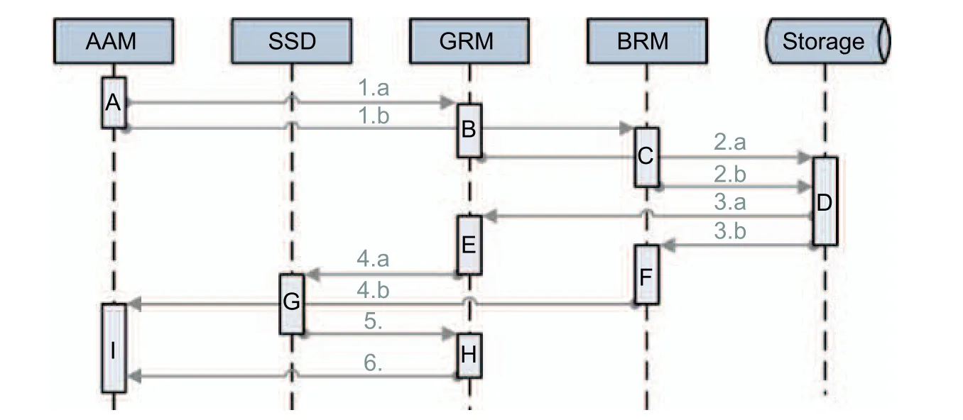
Fig.11.Sequence diagram showing the logical data flow of some involved Gridlink modules.
4. Conclusion and Outlook
We introduced a software ecosystem that allows modular applications to be plugged in (installed/started) and out (stopped/uninstalled) during the runtime of the node (plug and automate paradigm) and the concurrent execution of a high number of modules in an iSSN.Remote provisioning features allow issuing software maintenance commands from the remote operator side without requiring staff on-site.This is an essential aspect for cost efficiency, as grid operators are usually responsible for thousands of such stations.We furthermore raised potential security problems that may influence other modules.Thus, we introduced some security measures(trusted Gridlink Apps, Gridlink security layer) to limit allowed modules on one node and their communications.
The software ecosystem is in use in research projects in Seestadt Aspern, one of the currently largest smart city projects in Europe.Described applications have been developed during those projects and are in operation.The active integration of the smart building in the low voltage grid operation is ongoing; modules integrating energy data and forecasts of the smart BEMSs have been shown.We are investigating the mass-rollout of those applications to hundreds of stations.Once using the ecosystem in productive use cases, security issues need to be re-evaluated and improved countermeasures, especially for attacks that are not yet handled, and need to be introduced.
杂志排行
Journal of Electronic Science and Technology的其它文章
- Guest Editorial____________________________Special lssue on Energy-Efficient Technologies—Crowd Energy Applications
- Energy-Efficient Operation of Water Systems through Optimization of Load Power Reduction in Electricity Markets
- Options and Opportunities for Energy Management in Malaysian Grid Systems—Putrajaya as a Case Study
- lmplementation of Efficient B2G and V2G in Practical Cases
- lnvestigating Energy Prosumer Behaviour in Crowd Energy Using an lnteractive Model/Diorama
- Profitability of RE-Technology Regarding the Economic Environment: A Case Study of Swiss SMEs
