Improved lever arm compensation algorithm for initial alignment of SINS/odometer
2018-12-20GAOKangRENShunqingCHENXijunWANGZhenhuan
GAO Kang, REN Shunqing, CHEN Xijun, WANG Zhenhuan
(Space Control and Inertial Technology Research Center, Harbin Institute of Technology, Harbin 150080, China)
Abstract: Aiming at the initial alignment problem of vehicle based strapdown inertial navigation system(SINS), an odometer aided SINS initial alignment in-motion algorithm is proposed, and an improved lever arm model according to the characteristics of odometer output is put forward.Based on the observability analysis, a two-step on-line initial alignment method is proposed at first, in which the odometer scale factor error and the SINS installation error are calibrated in step 1, and then the attitude, inertial sensor biases and odometer’s lever arm are estimated in step 2.Then, the error equation of SINS/ odometer algorithm is derived and Kalman filter is designed to achieve initial alignment.Finally, the computer simulation and vehicle test are carried out.The simulation results show that the estimate error of the lever arm is reduced by 10% or more,which improves the estimation precision of attitude, and the vehicle test verify the efficiency of the algorithm.
Key words: SINS; odometer; lever arm effect; initial alignment; moving base
The inertial navigation system (INS) is an autonomous navigation system that uses the inertial measurement unit (IMU) and the initial position information to determine the attitude, position and velocity of the carrier[1-2].INS is widely used in aviation, marine, land vehicle navigation and positioning because of the advantage of complete autonomy[3].
The initial alignment is used to provide the initial states for INS and is one of the core technologies of INS[4].For SINS in weapon system, it is important to be able to achieve high precision alignment on moving base[5-6].Unlike the alignment on the static base, the alignment on moving base usually requires the carrier motion information provided by external device, for example,global positioning system (GPS), camera, odometer and Doppler laser radar.
Odometer is a kind of cost-effective and conveniently-deployed sensor for land vehicles.In literature[7], MEMS-IMU/Odometer/GPS integrated navigation is adopted, and the odometer output is used to assist the SINS navigation when the GPS signal being limited.Xu[8]proposes a dual-model initial alignment (DMIA)method to solve the problems of odometer aided SINS initial alignment and improve the alignment performance.Wu[9]systematically proposes a versatile strategy for self-contained land vehicle navigation using the IMU and an odometer.In literature [10], a novel backtracking alignment scheme is employed for DVL-aided SINS.
The compensation of lever arm effect error is one of the main research contents of initial alignment.The lever arm effect compensation for missile inertial measurement unit is studied in literature [11].In literature [12], an algorithm is proposed to estimate the length of the lever arm firstly by unscented Kalman filter (UKF), and then to compensate the speed caused by lever arm effect.Literature [13]adopts FIR and IIR low-pass filtering methods to deal with the lever arm effect in the frequency domain and filter out the interference acceleration information of the lever arm effect.
Lever arm uncertainty acts as a major error source of SINS/Odometer in accurate applications.However, in most existing literatures about SINS/Odometer integrated navigation system, the lever arm effect caused by installation position’s coincidence is ignored, or the traditional SINS/GPS lever arm model is used directly[14].In literature [15], the output of the odometer is taken as distance increments including the speed in three directions.Unfortunately, the decomposition model given is too complicated and has not been well applied in the subsequent study.In this paper, a kind of improved lever arm model is designed for odometer, and a novel SINS/Odometer in-moving initial alignment method based on this model is proposed.
The contents are organized as follows.Section 1 presents the error model of the odometer scale factor and the SINS misalignment angle, and proposes a novel lever arm model.Section 2 conducts the observability analysis of the SINS/Odometer integrated navigation system, and proposes an SINS/Odometer online calibration method including two steps based on the observability analysis results.Section 3 reports simulation results of the algorithm.Conclusions are finally drawn in Section 4.
1 System description and model
1.1 Coordinate frames
In order to better understand the initial alignment, it is necessary to explain the navigation coordinate system,that is, the earth frame (e-frame), the navigation frame(n-frame), the vehicle frame (a-frame), the SINS frame(b-frame), and the odometer frame (m-frame).The relationship among a-frame, b-frame and m-frame is shown in Figure 1.And the position installation error between the IMU and odometer isbl as shown in Fig.1.These frames are defined in detail as follows.
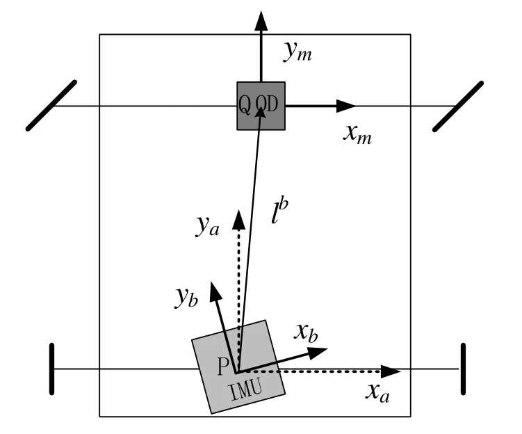
Fig.1 Relationship among a-frame, b-frame and m-frame
e-frame: The earth’s core is the origin, and xeaxis points to the intersection of the prime meridian and the equator.zeaxis goes upward along earth polar axis.xe,ye, and zeform a right-hand coordinate frame.e-frame rotates in inertial frame with angular rate ωie.
n-frame: Its origin is the centroid of the vehicle.znaxis goes upward along the local geodetic vertical , ynaxis and xnaxis point the horizontal north and east respectively.
a-frame: Its origin is the center of the back axle, the point P.xbaxis shifts rightward along the vehicle’s transverse axis, ybforward along the longitudinal axis,and zbupward along the vertical axis.
b-frame: Its origin coincides with the origin of the vehicle frame, and the axes are implicitly defined by configuration of the three gyroscopes/accelerometers,which misalign the a-frame axes in attitude.
m-frame: Its origin is the center of the front axle, the point Q, and the m-frame coordinate axes are parallel to the three coordinate axes of the vehicle frame respectively.
1.2 The odometer scale factor error model
Assume that the vehicle is in motion, the wheels do not slip and taxi, keeping on the road, and odometer is installed in the front of the vehicle.The odometer outputs the speed in the forward direction of the body.The odometer speed output in m-frame is expressed as

where, vDis the output of the odometer.
In practice, the scale factor error is the main error of the velocity vector error.The scale factor of the odometer was calibrated before application.However, during the course of vehicle travel, the change of the odometer scale factor resulting in measurement error is often caused by the change of the road conditions, the ambient temperature, the tire wear, and the vehicle load.Taking the scale factor error δDK into account, the odometer speed output in m-frame is expressed as

Where, δDK is assumed as constant, i.e.
1.3 The SINS misalignment angle model
Denote the misalignment angle between b-frame and m-frame asthen the installation error matrixcan be expressed as

Where, ‘c’ is short for ‘cos’, and ‘s’ is for ‘sin’.
The speed of the odometer output expressed in the b-frame is

Obviously, the rollyαhas no effect on
If the misalignment angle is small angle, the equation (4) can be simplified as

The misalignment angle is considered as constant,i.e.
1.4 The traditional lever arm effect model
Denote the displacement between odometer and IMU as.The speed at the odometer measurement point can be expressed as

The component form of equation (6) can be expressed as

In the traditional lever arm model, the output of the odometeris the forward speed componentof the vehicle.In this case, the speed information of SINS is expressed as

It can be seen from the above equation, when the vehicle has an attitude maneuvering,will have the velocity components in the sideway and the vertical direction, which is clearly contradictory with the assumption that the SINS coordinate frame coincides with the vehicle coordinate frame and the vehicle speed only contains forward component.Yan[15]considers the odometer’s output contains the components of the leftright and the vertical direction, unfortunately, the decomposition model is too complicated and has not been well applied in the subsequent study.
1.5 The improved odometer lever arm effect model
Assuming the vehicle is running, the wheels do not slip and bounce, closing to the road, with only heading and pitch turn, thereforethen equation (7) can be reduced to

The odometer measures the increment of the distance traveled by the front wheels of the vehicle, so the output of the odometeris the resultant of velocity components in three directions.According to equation (8), the velocity measurement of odometer can be expressed as

Obviously, this model only needs the value of forward lever arm.
2 The novel initial alignment method
2.1 The global observability analysis
The navigation (attitude, velocity and position) rate equations in the reference n-frame are well known as

Rewrite equation (12) as

Take the derivative of both sides of

Take it into equation (13)

If the carrier has no attitude maneuver, thenandare small amount.Equation (15) can be simplified as

Substituting equation (4) into equation (16), we have

Make derivatives with respect to time on both sides:

Take the mode of both sides:

In general, the odometer scale factor is positive,

Rewrite equation (18) into the following form:

It is obviously that the SINS misalignment angle xandcan be calculated from equation (21).That is, if the vehicle has no attitude maneuver, the odometer scale factor and the SINS misalignment angle require only the vehicle acceleration to be estimated.So, we can calibrate the odometer scale factor and the SINS misalignment angle firstly without knowing the other error parameters.
Based on the above results, a novel initial alignment method including two steps is designed as follows.
Step 1: We ignore the lever arm at first, and the initial attitude, the inertial sensors’ bias, odometer scale factor, and SINS misalignment angle are taken as the system errors.The main issue in step 1 is to estimate the odometer scale factor and the SINS misalignment angle through accelerating.
Step 2: Compensate the odometer scale factor and the SINS misalignment angle that estimated in step 1 for the system.Then, the initial attitude, the inertial sensors’bias and lever arm are estimated from UKF in step 2.
Above is the fundamental principle of this paper as shown in Fig.2.

Fig.2 Flow char of the initial alignment method
2.2 The system error equations
2.2.1 DR position error equations in step 1
The dead reckoning (DR) is a commonly used carrier independent positioning technique that uses posture, heading, and mileage information to calculate the vehicle’s position relative to the starting point.In this paper, the angular increment from gyroscope output in SINS and the position increment from odometer output are used to realize the dead reckoning.The dead reckoning algorithm includes the position updating algorithm and the attitude updating algorithm.
Define the body attitude matrix with respect to the n-frame as, which is calculated by the gyro combination in SINS, and the subscript D means the variable output by the dead reckoning algorithm.
The velocity output of the odometer is expressed in the navigation coordinate system as

The position differential equations are similar to the SINS position update equations and can be expressed as
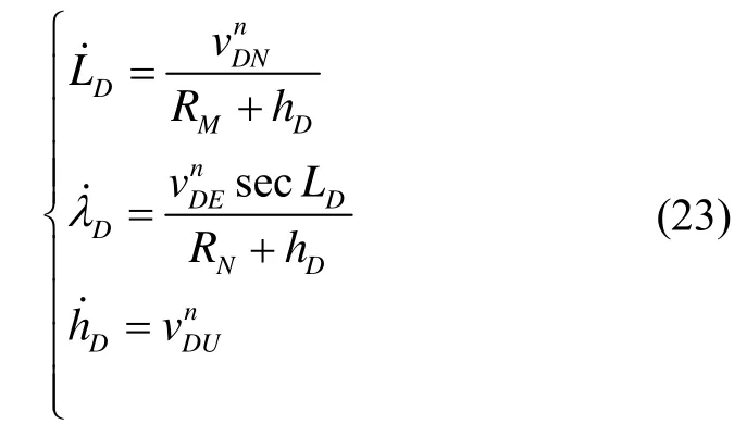
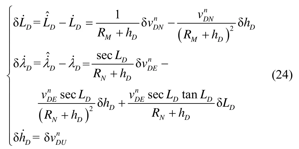
Then, considering velocity error, the position error of dead reckoning can be expressed as
In n-frame, considering attitude error, odometer scale and SINS misalignment angle, the speed output from odometer can be expressed as

The velocity error is defined as the calculated value minus the true value.Ignoring the second order small quantity, the speed error expression is

Substituting equation (26) into equation (24), then

where,
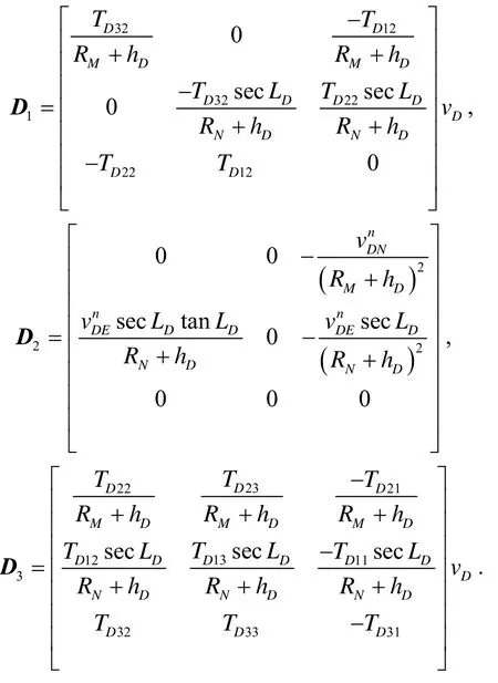
2.2.2 DR position error equation in step 2
Assume that the scale factor error of the odometer and the SINS misalignment angle have been accurately compensated, then the odometer velocity considering the lever arm effect is

Then, the velocity error is

Substituting equation (29) into equation (24), we will get the position error equation of dead reckoning.It is obvious that the equation is non-linear.Therefore, the nonlinear filter UKF is adopted to estimate the error state of the system.
2.2.3 SINS error equations
The attitude, velocity and position error equations of strapdown inertial navigation system are given directly as follows:
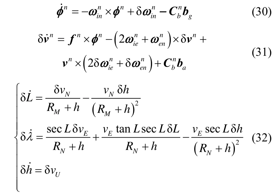
Where the symbols without the subscript D mean the corresponding variables of SINS.
2.3 The initial alignment based on Kalman filter
2.3.1 The KF equations in step 1
The SINS attitude error, velocity error, position error, gyro drift, accelerometer bias, DR position error,odometer scale factor error, and SINS misalignment angle are taken as system states.According to equations(27), (30)-(32), the system state equation is Where,is the system noise.

The differences between the positions output by SINS and DR are chosen respectively as observation parameters.

The system measurement equation can be expressed as where,is the measurement noise.

2.3.2 The KF equations in step 2
The SINS attitude error, velocity error, position error, gyro drift, accelerometer bias, DR position error,and lever arm are taken as system states.According to equation (29), (30)-(32), the system state equation is

The differences between positions output by SINS and DR are chosen respectively as observation parameters:

The system measurement equation can be expressed as where,is the measurement noise.

3 Simulations and experiments
To verify the performance of the proposed lever arm model for initial alignment algorithm, simulations and experiments are performed in this section.
3.1 Simulation and analysis
The INS is assumed to be located at medium latitude 45° and equipped with a triad of gyroscopes(drift 0.02 (°)/h, noise 0.2 (°)/h) and accelerometers (bias 100 μg, noise) at a sampling rate of 100 Hz.The SINS misalignment angle is [20′ 10′ -30′]T.The odometer is displaced from the INS by the lever armand the odometer scale factor error is 0.002.White velocity noise (standard variance 0.02 m/s) is simulated in odometer measurements.The initial attitude error is [1° 1° 10°]T, and the initial position error is 10 m for each direction in latitude,longitude and height.
The vehicle trajectory is designed as follows.The total simulation time is 1000 s.The maneuver mode includes accelerating, turning, pitching and slowing down.The vehicle’s running trajectory is shown in Fig.3, and the IMU outputs are shown in Fig.4.
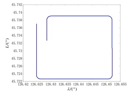
Fig.3 The vehicle’s trajectory
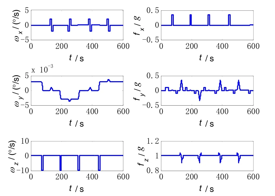
Fig.4 IMU outputs
As shown in Fig.5, the odometer scale factor is effectively estimated after the vehicle accelerating, with an estimated error of 0.01%, and the SINS misalignment angle is also effectively estimated after the vehicle accelerating.The estimated values before 60s will be taken into the system as accurate known value.

Fig.5 The estimate error of odometer scale factor and SINS misalignment angle
Figure 6 is the estimation result of lever arm.The top two figures (blue line) are the estimation result of the traditional lever arm model, and the estimation error of the traditional model in the x direction and z direction is close to 0.1m at the end of the simulation.The third figure (red line) shows the estimation results of the improved lever arm model, the estimation error is about 0.07 m.It is obvious that the improved lever arm model has advantages not only in estimated accuracy, but also in convergence speed.
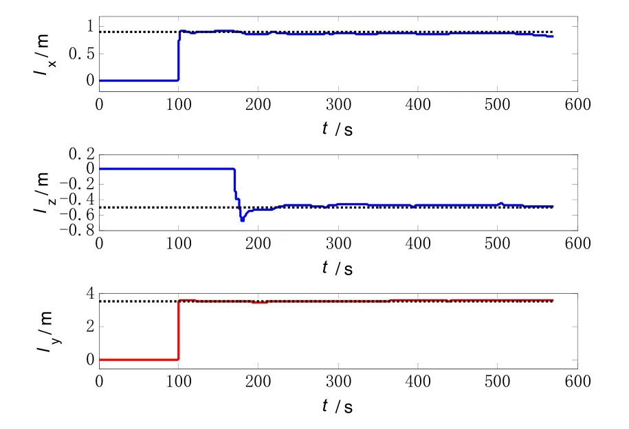
Fig.6 The estimate results of lever arm
The estimate results of attitude error is shown in Fig.7, the blue dashed line denotes the estimated results of traditional model with the estimate error of [-1.6441′1.5309′ 1.5147′]T, while the red solid line is the estimated results of the improved model with the estimate error of [-1.6445′ 1.4680′ 0.5148′]T.
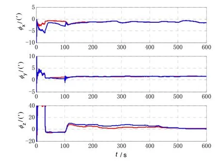
Fig.7 The estimate results of attitude error
3.2 Vehicle test
The vehicle test was conducted to validate the actual performance of the proposed algorithm.The system parameters are the same with those of the simulation.A high-precision GPS equipment was chosen as position reference, and the attitude reference was given by SINS/GPS integrated navigation system.The vehicle test trajectory is shown in Fig.8, and the velocity measured by odometer is shown in Fig.9.The estimate results of attitude error is shown in Fig.10, the blue dashed line denotes the estimated results of traditional model with the estimate error of [1.4144′ -0.1653′ 6.4074′]T, and the red solid line is the estimated results of the improved model with the estimate error of [1.5430′ 0.8277′-1.0034′]T.It is clear that the estimated result with the improved method is still relatively better as expected.

Fig.8 The vehicle test trajectory

Fig.9 The output of the odometer
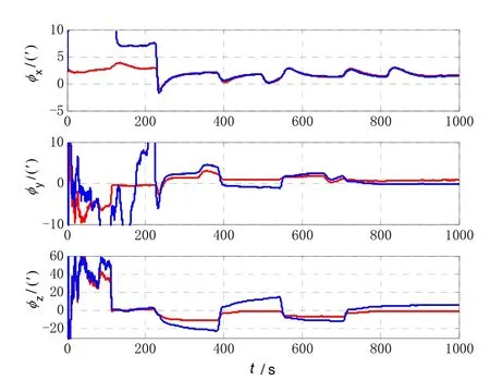
Fig.10 The vehicle test results of attitude error
4 Conclusions
In order to solve the SINS initial alignment problem of land vehicle in-motion, and a novel initial alignment method of the SINS/Odometer integrated navigation system was proposed in this paper.The main focus of this manuscript was establishing an improved lever arm model aiming at SINS/Odometer.On the basis of the global observability analysis, a novel initial alignment method including two steps is presented.By calibrating the odometer scale factor and SINS misalignment angle at step 1, the system error equations are simplified, and the initial alignment efficiency is improved.To verify the effectiveness of the lever arm model and the initial alignment algorithm, the simulations were carried out,and the results show that the improved lever arm model is more accurately than the traditional one, and the novel initial alignment method is more effective when the road curves more.And the vehicle tests verify the effectiveness of the method in practical application.The method does not impose a harsh limit on the maneuver of the vehicle, and has a good engineering application prospect.
