基于多孔基片聚合物注入方法的薄膜固体氧化物燃料电池无支撑薄膜制备研究
2018-11-29苏芝玄金有圣郑春花张翼滉车硕源
苏芝玄 金有圣 郑春花 张翼滉 车硕源
1(首尔大学 首尔 151742)
2(中国科学院深圳先进技术研究院 深圳 518055)
3(圆光大学 益山 54538)
1 Introduction
Recently, side effects of the non-renewable energy abuse on the nature have been revealed to the public.Along with the severe environmental problems, the solid oxide fuel cell (SOFC) seems to be a good replacement resource satisfying current demands on the energy. The SOFC is categorized as the third generation fuel cell which presents high efficiency,low catalyst cost, and the ability to internal reforming. However, the operating temperature of SOFC is relatively high (700-1 000℃), which limits the commercialization due to thermal stability, long start-up time, and sealing problems[1-4].
Many researches have been conducted to reduce the operating temperature of SOFC. One of the most actively studied areas is the fabrication of electrolytes as thin films. By fabricating the electrolyte as a thin film which ranges from tens of nanometers to several micrometers, the ion conductivity of the electrolyte can be improved so that lowering the operating temperature of SOFC is possible[5-10].However, one important required precondition when fabricating a thin film electrolyte on a porous support is to make the electrolyte without pinholes. These pinholes cause problems such as gas crossover and electrical shortage, which lead to an increase in the leakage current and furthermore the degradation in cell performance. In order to make an electrolyte thin film without pinholes, when applying the thin film on a porous substrate with microscale pores,the pore size should be adjusted from several tens of nanometers to several hundreds of nanometers.The thickness of electrolyte is determined by the modified pore sizes[11]. One approach of modifying the pore size is the graded anode, which reduces the particle size by the anode functional layer(AFL)[12-15]. Recently, AFL method stacking different pore size layers in order has been commonly applied to the thin film SOFC. However, additional sintering process for each layer requires a lot of processing time in this method. Also, the high sintering temperature (above 1 000℃) limits the material selection and manufacturing method of the fuel cell components. In addition, the particle size and the thickness change inevitably depend on the pore size of substrate.
Opposite to current AFL method, a new method is proposed in this research, in which polymers are filled into the empty spaces inside the substrate until it appears to have the desired pore size. Out of engineering plastics, the melting point and pyrolysis temperature of the polystyrene are relatively low.Moreover, it is easy to process and inexpensive.In this research, the polystyrene is injected into a porous nickel oxide yttria-stabilized zirconia (NiOYSZ) substrate making it as an AFL, and the freestanding thin film on the porous substrate by the new method is finally fabricated. The surface morphology and cross-sectional structure of the free-standing thin film on the porous substrate are analyzed by field emission scanning electron microscope (FE-SEM)and focused ion beam scanning electron microscopy(FIB-SEM).
2 Experiment
For NiO-YSZ cermet, the commercial NiO (Wako,USA) and YSZ (8 mol%, Kceracell, Korea)powders, the starch, and the butvar (Sigma Aldrich,USA) were ball milled with zirconia ball for 24 hours. The weight ratio of the starting materials was 60∶40∶10∶0.5. The milling was carried out in the isopropyl alcohol, and the mixture was dried at 80℃to remove the isopropyl alcohol. For the preparation of green body, the mixed NiO-YSZ powder was first pressed under 50 MPa into a substrate in a steel die with 15 mm diameter. After that, the body was sintered at 1 250℃ for 10 hours in the air, and a porous NiO-YSZ pellet was obtained. 10 mm diameter disk chips of polystyrene (Wako, USA)placed on the top of NiO-YSZ substrate were melted at 260℃ till the liquid phase, and maintaining the temperature at 260℃ for 30 minutes for a complete phase change. Then, the polystyrene was injected into the porous NiO-YSZ substrate with a 40 MPa force for 20 minutes. After the solidification of the polystyrene, the composite substrate was mechanically grinded by a horizontal grinding machine (HRG-150, AM Technology, Korea) using 320 mesh resin diamond wheel with 2 500 RPM(revolutions per minute) to obtain a smooth substrate surface with the polymer porefillings. The NiO-YSZ nano-composite thin film electrode was deposited onto the polystyrene-NiO-YSZ composite substrate using a direct-current and radio frequency magnetron co-sputtering system. The NiO-YSZ nano-composite thin porous film was prepared with Ni and Y/Zr alloy targets (Y0.16Zr0.84, RnD Korea, 99.9%) and cosputtered for 0.5 hour. An radio frequency power of 200 W was maintained for the YSZ target and a power of 100 W was applied to the Ni target. The pressure of the sputter chamber was maintained at Ar/O2(8∶2) 5 mTorr. The Ni was deposited as NiO and the Y/Zr as YSZ through a reactive sputtering.Using the sputter, NiO-YSZ thin film was deposited under 300 nm on the composite substrate as anode buffer layer. Thereafter, the polystyrene in NiOYSZ pores was removed by keeping it under 460℃for 4 hours. The experiment steps are shown in Fig. 1.
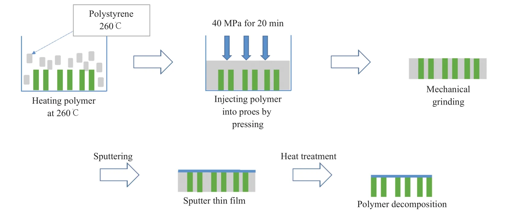
Fig. 1 Schematic of polymer injection method
For comparison, another sample was also prepared by directly depositing the NiO-YSZ thin film without the pore blocking process through polystyrene. The surfaces of samples obtained from the pore-blocking and the pore-blocking-free methods were observed through FE-SEM. The cross sections of two samples were also observed through FIB-SEM.
3 Results
The pore size and porosity of the anode electrode are the main macroscopic parameters to influence its performance. FE-SEM images of two samples are shown in Fig. 2, which are obtained through depositing the NiO-YSZ thin film by sputtering under the same condition. Fig. 2(a) shows the thin film deposited on non-treated NiO-YSZ cermet surface, while Fig. 2(b) shows that deposited on the top of NiO-YSZ cermet surface with the post pyrolysis of polystyrene. Fig. 2(c) is the enlarged image of the certain part of Fig. 2 (b). It is observed from Fig. 2(a) that the diameter of the circular pores is 8 µm or more. Thus, it is difficult to prevent pores to have a diameter of 8 µm or more by a general thin film deposition method. It has been found that the thickness of the thin film should be at least the diameter size of the minimum pore in order to prevent pores. In conventional AFL method, the electrode with AFL consists of gradient layers, so that the pore size becomes gradually smaller from the bottom to the top layers. Even though the pore size and its structure are controlled in AFL method,lots of complicated processes in terms of controlling microstructure layers are required per each layer.
Despite the conventional complicated method and regular thin film deposition, in case of Fig. 2(b)shows obvious differences compared to Fig. 2(a),in which less number of pores are observed because of the polymer injection method. Furthermore,the surface has light bumps in Fig. 2(b) due to the polymer injection and its heat treatment. During the procedure, the amount of polystyrene used is way enough than the right amount to inject into the pores neatly. Less pores are captured and the shape is not circular but slender. Most pores are long and bending in random or seem like loops. The loop-type pores are presumably generated by the fact that the liquidto-solid phase change of polystyrene shrinks occurs,and therefore there is a portion of pores that cannot be filled with the polymer. Even though the surface looks rough and bumpy, the mechanical grinding used before the thin film deposition helps to obtain a fine thin film.
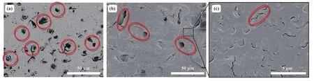
Fig. 2 Field emission scanning electron microscope (FE-SEM) images of (a) without the pore blocking process, (b) post pyrolysis NiO-YSZ cermet support surfaces and (c) enlarged image of Fig. 2(b)
In Fig. 2(c), pores under 500-nm-thick size located in a look-alike smooth surface are enlarged.Besides the well-marked pores, slight slender shape pores are occurred less than a micro-size scale. Also,these pores do not seem to have a depth but little tears or half round boundary lines. Compare to pores from previous images, the size of these tears or hook shapes is very small to cause pinholes within an electrolyte. Even though the pore size is degraded through the proposed method, the cermet anode should also be capable for the triple phase boundary with small pores maintaining high level activation and gas permeability. We believe the optimization of certain amount of the porosity with small size of pores shown in Fig. 2(c) is needed to hold right amount of gas permeability. Along with the pore size, it is also believed the porosity is also affecting the anode performance relating to the triple phase boundary.
Using the software Image J, the porosity and pore size of the equal area are examined. Since the pore shape of Fig. 2(b) is particularly hard to examine,a black and white color comparison method from image J is used. Overall, the pore size decreases from 8 µm in Fig. 2(a) to 2.3 µm in Fig. 2(b). The porosity in Fig. 2(a) is 7% and 1.5% in Fig. 2(b).Fig. 2(c) is not measured separately because the area is already covered in Fig. 2(b).
4 Discussion
With FE-SEM images, the polymer injection method is proved to degrade the pore size and even the porosity similar to the conventional AFL method resulted. The extended aim of this method is to apply it to the free standing thin film SOFC field such as tape-casting AFL, screen printing AFL and others.Free-standing thin films are fabricated mainly by the physical/chemical etching. In this study, the freestanding thin film is successfully fabricated by filling pores with the polymer and removing it through pyrolysis. In Fig. 3(a), the thin film is located on the top of porous substrate. The cross-section image of the polymer-injected sample is observed through FIB-SEM as shown in Fig. 3(b) and Fig. 3(c). In Fig. 3(b), on the porous substrate from polymer injection method, there are NiO-YSZ anode layers.Underneath the free standing structure, pores are once cleared after pyrolysis. With the enlarged cross-sectional view in Fig. 3(c), it is confirmed that the thin film is separated from the support and in the free-standing state. With the fabrication of free standing film, the injection method approaches its ultimate goal of applications as the conventional AFL method. Through degrading the pore size and porosity within a layer, unlike the AFL method which requires several layers stack for smaller pore size, polymer injection method is effectively able to fabricate free standing thin film.
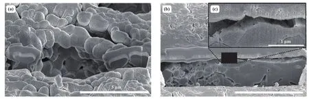
Fig. 3 Focused ion beam (FIB) images of (a) free standing structure on post pyrolysis NiO-YSZ cermet, (b) cross-sectional free standing structure on post pyrolysis NiO-YSZ cermet and (c) enlarged free standing structure of Fig. 3(b)
5 Comparison and Analysis
The existing AFL is made through various complicated processes, and there are many conditions under preparation for making a functional layer[12-15]. It requires multiple sintering steps under more than 1 000℃ and even requires the grinding for a smooth surface. One functional layer is completed by annealing after depositing nano-particles by pulsed laser deposition. It is very time consuming and sensitive to create AFL by combining multiple layers including buffer layers and reduce the nanoparticle size. The tape-casting is the most commonly used and proven method to make the AFL layer by layer with controlled- fine pore size[6]. However, due to high sintering temperature, the nanostructures are clustered together and even destroyed. Unlike the tape-casting method, the polymer injection method proposed in this research, operating at the melting point of the polymer of 260℃, has an advantage in maintaining nanostructure. In addition, fabricating the free standing thin film is usually using physical/chemical etching and complicated with limited conditions. In this study, the free standing thin film is relatively easy to fabricate by filling pores with polymer and removing it through pyrolysis.
6 Conclusion
To overcome the weakness of the AFL method such as delicate procedures, high sintering temperature,and long time, the polymer injection method to control the pore size of the cermet surface is proposed and validated in this research. The polystyrene is selected as the injecting polymer due to the excellent heat processability and low cost.Through the proposed method, the diameter of the pore on the cermet support surface decreases from 8 µm to 2.3 µm for comparing maximum pore sizes.The polymer injection is effective and direct method to fabricate the nano-sized pore cermet. The freestanding thin film is also successfully fabricated by thermal decomposition without any masking and chemical or physical etching system and any restricted conditions.
7 Future Work
Furthermore, this research will continue to fabricate the full-structured stacking anode, the electrolyte,and the cathode layers by sputter. The method proposed in this research proves that the pore size and porosity can be controlled with the advantages against the conventional AFL methods, such as tape-casting. Single cells fabricated by several conventional AFL methods and the polymer injection method will be compared in terms of the electrochemical performance. The present work will also continue to gain a deeper and systematical understanding of the relationship between pore size and porosity with the electrochemical performance via X-ray diffraction, electrochemical impedance spectra and scanning electron microscopy (SEM)images.
