Service Function Chain Orchestration across Multiple Clouds
2018-10-13XuxiaZhongYingWangXuesongQiu
Xuxia Zhong*, Ying Wang, Xuesong Qiu
State Key Laboratory of Networking and Switching Technology, Beijing University of Posts and Telecommunications, Beijing 100876, China
Abstract: Network function virtualization is a new network concept that moves network functions from dedicated hardware to software-defined applications running on standard high volume severs. In order to accomplish network services, traffic flows are usually processed by a list of network functions in sequence which is defined by service function chain. By incorporating network function virtualization in inter-data center (DC) network,we can use the network resources intelligently and deploy network services faster. However,orchestrating service function chains across multiple data centers will incur high deployment cost, including the inter-data center bandwidth cost, virtual network function cost and the intra-data center bandwidth cost. In this paper, we orchestrate SFCs across multiple data centers, with a goal to minimize the overall cost. An integer linear programming(ILP) model is formulated and we provide a meta-heuristic algorithm named GBAO which contains three modules to solve it. We implemented our algorithm in Python and performed side-by-side comparison with prior algorithms. Simulation results show that our proposed algorithm reduces the overall cost by at least 21.4% over the existing algorithms for accommodating the same service function chain requests.
Keywords: network function virtualization;service function chain orchestration; inter-DC network
I. INTRODUCTION
In order to accomplish network services,traffic flows are usually processed by a list of network functions (NFs) according to a particular order. The sequence of network functions is known as service function chain (SFC) [1].Network operators implement SFCs by steering flows to the hardware middleboxes located in local networks. Traditional hardware-based network functions exhibit significant limitations in terms of network flexibility, scalability, manageability and operational efficiency[2]. Therefore, SFC orchestration will incur high deployment and maintenance cost [3].
Fortunately, network function virtualization(NFV) emerges as a new network architecture which decouples the middleboxes from the dedicated hardware appliances and implements them as virtualized network functions running on commercial off-the-shelf equipment [4]. With NFV, traditional middleboxes can get implemented as software building blocks in the form of virtual machines (VMs)running on industry standard high volume servers, switches and storage [5]. The flexibil-ity, agility, capital and operational cost savings and scalability of NFV breaks the limitation of traditional middleboxes. Such an approach realizes to reduce capital expenditure (CAPEX)and operational expenditure (OPEX) for service deployment [6].
Recently, with the rise of cloud computing and big data, inter-data center (inter-DC) networks that connect geographically distributed data centers have been deployed rapidly [7].As public clouds in inter-DC networks usually offer a pay-as-you-go charging system and support elastic service scaling, the operational cost and complexity of maintenance can be significantly reduced [6]. By implementing virtual network functions (VNFs) in inter-DC networks, network operators can use the network resources more flexibly and deploy services cheaper and faster. Furthermore,there are already several architectures (e.g.,APLOMB [8] and Jingling [9]) proposed to migrate the virtual network functions from local networks to inter-DC network. These architectures can provide technical approaches for network operators to orchestrate their service function chains to inter-DC network.
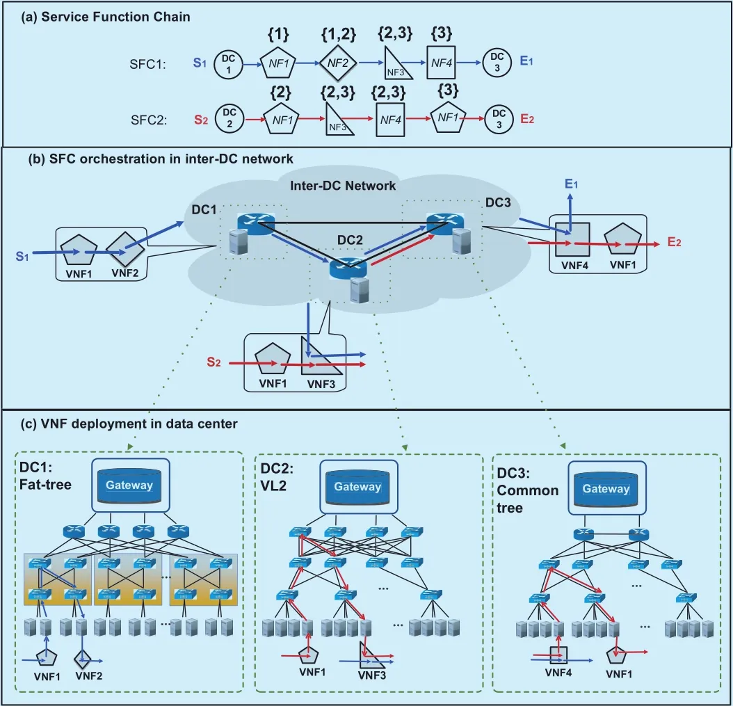
Fig. 1. (a) Service function chains (b) SFC orchestration in inter-DC network (c)VNF deployment in data center.
We investigate to orchestrate SFCs in an inter-DC network, with a goal to minimize the overall cost.
Figure 1 shows an example of the SFC orchestration in an inter-DC network. There are two SFCs to be orchestrated in Figure 1(a), SFC1 originates from S1, and its data needs to be processed by NF1→2→3→4 in sequence and sent to E1; SFC2 originates from S2, and its data needs to be processed by NF1→3→4→1 and sent to E2. Moreover,each NF has a preferred data center location.For example, {1,2} above NF2 of SFC1 means it can be deployed in DC1 or DC2.Other SFCs are demonstrated in the same way.Figure 1(b) shows the orchestration results.We can see SFC1 passes through the VNF1,2 in DC1, traverses the VNF3 in DC2, finally reaches to VNF4 in DC3; SFC2 passes through the VNF1, 3 in DC2 and traverses the VNF4, 1 in DC3. There are three types of costs generated during the orchestration:
1) Inter-DC bandwidth cost:it is common to orchestrate SFCs across geographically distributed data centers to meet the location constraints or performance requirements [6].For example, proxies and caches should be deployed near to the enterprise network, packet filters should be placed close to traffic sources for increased bandwidth conservation at the event of DoS attacks [10]. In Figure 1(b),SFC1 traverses through three data centers(DC1, DC2 and DC3), SFC2 only passes two data centers (DC2 and DC3) producing less inter-DC bandwidth cost. However the unit price of the inter-DC bandwidth is very expensive, cross-DC orchestration will generate high bandwidth cost [6].
2) VNF cost:although VNFs can be shared by multiple SFCs to improve the resource utilization, the VNF cost occupies an important part as hundreds or thousands of NFs need to be deployed on demand [11]. Besides, data centers offer various types of VNFs with different unit prices and processing capacities,therefore it is difficult to deal with the incoming VNFs cost-efficiently. In Figure 1(b), the VNF3 in DC2 and VNF4 in DC3 are shared by SFC1 and SFC2, there are a total of 6 VNFs in use to orchestrate SFC1 and SFC2.
3) Intra-DC bandwidth cost: the data-in-tensive NFV-enabled applications require high network bandwidth to deliver maximum packet throughput, therefore they consume high intra-DC bandwidth when VNFs deployed in the same data center communicate with each other [12]. Moreover, current data centers in inter-DC network are commonly designed as a three-tier architecture such as common tree,VL2 and fat-tree [13]. Figure 1(c) depicts the communication of VNFs in DC1(fat-tree),DC2(VL2) and DC3(common tree). The deployment location of the VNFs will influence the bandwidth cost of the intra-DC communication.
Taking into account the three types of costs mentioned above, there exists two major challenges when orchestrating SFCs in an inter-DC network:
Challenge 1: How to orchestrate SFCs in inter-DC network with less overall cost?Most of the current works only consider the inter-DC bandwidth cost, and ignore the VNF cost and intra-DC bandwidth cost [6][14][10].However, in an off-line SFC orchestration environment where hundreds or thousands of NFs need to be deployed on demand, the VNF cost occupies an important part. Besides, the data-intensive communication within a DC will create high intra-DC bandwidth cost.
Challenge 2: How to deploy VNFs within a three-tier architecture data center? Different architectures have been designed with different packet forwarding strategies. For example,VL2 randomly selects an aggregation and a core switch to forward traffic in order to balance the load across all available links; fattree is built around the concept of pods, where the communication between the VNFs in the same pod do not need to traverse a core switch[13]. The deployment location of the VNFs will influence the intra-DC bandwidth cost.Therefore, the data center architecture should considered to decrease the intra-DC bandwidth cost.
In this paper, we investigate to orchestrate SFCs in an inter-DC network, with a goal to minimize the overall cost. The contributions of this work are concluded as follow:
1) Firstly, a comprehensive cost model is generated and it contains the inter-DC bandwidth cost, VNF cost and the intra-DC bandwidth cost. We formulate the problem as an integer linear programming problem and prove the NP hardness of this problem.
2) Secondly, the orchestration procedure is divided into three phases: service function chain partition (SFCP), virtual network function consolidation(VNFC) and service function graph deployment (SFGD).
3) Thirdly, when deploying VNFs within a data center, we design algorithms tailored for different architectures (common tree, fat-tree and VL2).
4) Lastly, we design an meta-heuristic algorithm GBAO which contains three modules to deal with the three phases (SFCP, VNFC and SFGD) respectively.
The rest of the paper is organized as follows. Some related works are presented in section 2. Section 3 explains the mathematical model and problem formulation in detail. Section 4 illustrates the orchestration procedure.Section 5 presents our proposed algorithm GBAO. Extensive simulations and experimental results are explained in section 6. Lastly,we give a brief conclusion in section 7.
II. RELATED WORK
Some papers investigated the off-line SFC orchestration in single domain. M. C. Luizelli in [3] studied the NFV chaining problem in single domain. In their orchestration scheme,the VNF instances could be shared by multiple SFCs. However, they only considered the usage of VNF instances when orchestrating SFCs, therefore this cannot be applied into the situation of multiple domains. A. Tosti et al. in [15] proposed an off-line algorithms for SFC routing. Their orchestration objective was to maximize the number of accepted SFC requests while considering the server capacity and link bandwidth. Q. Sun et al. in [16]placed service function chain considering the affiliation character between the VNFs. SFCs with the same source-destination pairs were merged into a graph before orchestration.However, as the cost of cross-DC bandwidth was more expensive than VNF instances, SFC merging would result in higher bandwidth request leading to more bandwidth cost, it cannot be applied to the inter-DC network. J.Zhu et al. in [17] proposed a preplanned VNF placement and scaling scheme for resource saving and overhead reduction. However, they did not consider the sharing of VNF instances in [17] so that the orchestration complexity is reduced. X. He et al. in [18] presented two placement strategies (tenant-centric and service-centric) for deploying virtualized network services. Then they quantified the benefits and overheads of the two placement strategies using an experimental evaluation. All the aforementioned investigations were conducted under a single domain and cannot be directly applied to multi-domain network.
There are a lot of papers introducing diverse topologies of a data center, such as common tree, fat-tree and VL2 [19]. The three-tier common tree follows a multi-rooted tree based network topology composed of three layers of network switches, namely access, aggregate,and core layers [13]. The three-tier architecture uses enterprise-level network devices at the higher layers of topology that are very expensive and power hungry. However, it is one of the most common topologies in today’s data center net- work. Fat tree architecture employs commodity network switches based architecture using Clos topology and it is built around the concept of pods. Compared with com- mon tree, an advantage of the fattree topology is that all switching elements are identical, enabling us to leverage cheap commodity parts for all of the switches in the communication architecture [20]. VL2 is a data center network architecture that aims at achieving flexibility in resource allocation[13]. In VL2, all servers belonging to a tenant share a single addressing space regardless of their physical location meaning that any server can be assigned to any tenant. The separation between the addressing spaces of switches and servers improves the scalability of VL2 [21].
Some researchers have investigated the cross-domain SFC orchestration problem. J.Soares et al. in [14] tackle the service function embedding problem in multiple data center locations inter-connected through an operator network. However, they only selected the DC to place VNF requests from a multi-domain perspective and did not consider the placement inside each DC domain. D. Dietrich et al. in[10] presented a holistic approach to embed SFCs in multiple infrastructure provider’s scenario. They decomposed the embedding procedure into graph rendering, request partitioning and NF-subgraph mapping. Q. Zhang et al.in [22] presented a vertex-centric distributed orchestration framework for multi-domain networks. The physical infrastructure information was maintained locally within each domain,hence there was an orchestrator associated within each domain to manage all the resources and communicate with other domains. [10]and [22] were interested in multi-domain area,but they were not fully compliant with the scenario envisioned in this work, where there is one network domain and multiple DC domains. H. Chen [6] tackled the cost-efficient SFC orchestration prob- lem across multiple clouds. They formulated the problem into an ILP. However, there were mainly two differences between [6] and our work. Firstly, they only considered the VNF and inter-clouds bandwidth cost and ignored the intra-DC bandwidth cost. Secondly, they didn’t consider the sharing of VNFs.
A few papers have studied the impacts of the data center architecture on NFV type applications. P. Chi et al. in [23] designed a heuristic NFV deployment algorithm for VNF allocation, VNF placement and traffic dispatching according to user’s requirements and traffic flows. However, they only built their algorithm on a simple 3-tier tree topology. S.Herker et al. in [24] evaluated the data center architectures for virtualized network functions.They investigated the suitability of current data center architectures for NFV applications.S. Herker et al. also investigated the data center architectures impacts on the embedding of VNF service chain with high availability requirements in [12]. However, both of [24] and[12] did not provide orchestration strategy in topology-aware data centers.
III. PROBLEM FORMULATION
3.1 Network modeling
Service Function Chain. The service function chains to be deployed are represented byGV. One SFC in Gvis denoted by graph Gv=(Nv,Ev)∈GV, where Nvpresents the NF nodes and Evnotes the links between them. We use∈Nvto denote the ithNF node in Gv. As every NF has a type attribute(i.e., firewall, IDS, IPS, proxy, etc.), we useto describe the type of. Every NF must be deployed in its candidate data center set denoted by. In addition, letanddenote the requested resource and processing capacity of. We useto represent the link betweenand, andis its requested bandwidth.
Inter-DC network. The inter-DC network is denoted by graph GI=(DI,EI), where DIand EIdenote the data centers and the links in GI.is the link between data center dmand dn(dm,dn∈DI).andrespectively represent the bandwidth capacity and peering link cost for.
Data Center. dm∈DIrepresents a data center belonging to DI, and it can be modelled as a weighted undirected graph dm=(Hm∪Sm,Pm). There are two types of nodes in dm: hosts Hmand switches Sm. Pmnotes the links in dm. In this paper, we assume the routing path between hosts is determined in advance and we do not consider the routing within a data center. The routing paths between the uthhostand the vthhostare represented by. The hop number betweenandis represented bywhich is related to its architecture[25]. In this paper, we consider three types of architecture: common tree, VL2 and fat-tree.The architecture of dmis represented by ζm.The unit bandwidth price of dmis ηm. The type of VNFs is represented by setP. The VNF of type p(p∈P) in dmhas a specific cost, resource capacityand processing capacity. Furthermore, we assume each host can sustain a maximum of γ VNFs.
Service Function Graph. As the VNFspartitioned in each DC can be consolidated into service function graph (SFG). The SFG belonging tois denoted by Rm=(Vm,Lm),where Vmrepresents the VNF nodes and Lmrepresents the links between them.∈Vmrepresents the sthVNF in Rm, the type ofis denoted by. We useto indicate the link betweenand. The requested bandwidth ofis denoted by.All the notations are in Table 1.

Table I. Notations of orchestration problem.
3.2 Problem statement
As is demonstrated in Figure 1, there are three types of costs produced during the SFC chaining. With a goal to minimize the overall orchestration cost, we formulate the problem as an integer linear programming (ILP).
Objective:

Equation (1) is our objective function. The overall cost is denoted by C which is the sum of the inter-DC bandwidth cost, the VNF instance costand the intra-DC bandwidth cost. We will introduce them one by one in detail.
3.2.1 Inter-DC bandwidth cost
Variable:

Capacity constraint:
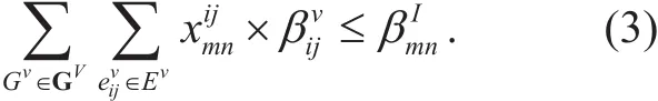
Equation (3) expresses the constraint of bandwidth capacity. The summation of all the requested bandwidth of flows passing through substrate linkmust be less than its available bandwidth capacity
Connectivity constraint:

Equation (4) refers to the flow conservation conditions. The net flow entering a node is zero, except for the source nodeand the sink node.
Inter-DC bandwidth cost:

The inter-DC bandwidth cost can be calculated based on the binary variable mentioned above. Equation (5) calculates the inter-DC bandwidth cost of.
3.2.2 VNF cost
Variable:

Capacity constraint:
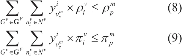
Equation (8-9) denote the capacity constraints. Equation (8) enforces the resource capacity bounds of VNF instance. It means that the summation of all the requested resource of NFs deployed inmust be less than or equal to its available resource.Equation (9) expresses the constraint of processing capacity. It denotes thatmust have enough processing capacity to manage all the NFs deployed in it.
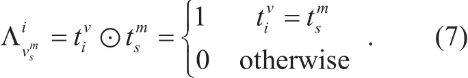
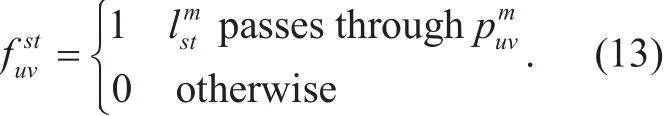
Location constraint:

Equation (10) makes sure that only one VNF instance is selected for every network function node, and the deployment location ofmust be within its candidate data center set.
VNF cost:
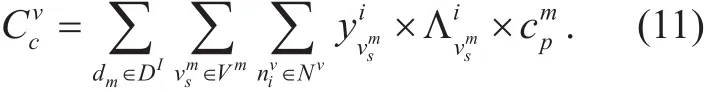
The VNF cost can be calculated based on the variable and constraints mentioned above.Equation (11) calculates the VNF cost of.
3.2.3 Intra-DC bandwidht cost
Variable:

Capacity Constraint:

Equation (14) represents no more than ϒ instances can be deployed in a host.
Location Constraint:
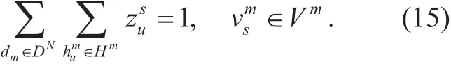
Equation (15) makes sure that only one host is selected for every VNF instance.
Intra-DC bandwidth cost:

Equation (16) denotes the intra-DC bandwidth cost ofdenotes the routing cost betweenand.is related to the architecture of dm. Different architectures provide different routing strategies.X. Meng et al. in [25] summarize the hop matrices of different architectures.
3.3 Complexity analysis
The problem of cost-aware SFC orchestration in inter-DC network is NP-hard.
Proof: We can prove the NP-hardness of the problem by restricting certain aspects of the original problems. We first apply the restriction that, which means that the unit price of intra-DC bandwidth is zero for all the data centers. Then the objective is to minimize the inter-DC bandwidth and NFV cost. Our problem is reduced to NFV location problem which is proved to be NP-hard in [26]. If we apply the restrictions that=0 and=0, thus the intra-DC bandwidth cost is the only factor to be considered. According to [25], deploying the SFC-graph in a three-tier data center can be transformed in to a Traffic-aware VM Placement Problem (TVMPP) which is a NP-hard Quadratic Assignment Problem (QAP).
IV. ORCHESTRATION OVERVIEW
As the problem of cost-aware SFC orchestration in inter-DC network is NP-hard, we divide the problem into three steps to reduce the complexity. Figure 2 shows an example of SFC orchestration procedure. An user requests for three SFCs (SFC1, SFC2 and SFC3). SFC1 needs to be processed by NF3→NF5→NF 2 in sequence. The set above each NF node denotes its location constraint. For example, set {1, 2, 3} above NF3 of SFC1 means it can be deployed in DC1,DC2 or DC3. Other SFCs are demonstrated in the same way. The three steps are as follow:
Step 1: Service Function Chain Partition (SFCP). SFCP determines the location of every requested NF node. It divides SFCs into multiple segments while satisfying the location requirement of every NF. The SFC requests are partitioned into sub-SFCs after SFCP. For example, SFC1 is partitioned into two parts: NF3→NF5 in DC2, NF2 in DC3. Other SFCs are partitioned in the same way. When traffic communicates between the NFs deployed in different data centers, there will produce inter-DC bandwidth cost. Therefore, SFCP influences the inter-DC bandwidth cost.

Fig. 2. SFC orchestration overview.
Step 2: Virtual Network Function Consolidation (VNFC). VFNC decides the usage of the VNFs. Sub-SFCs divided in the same DC are consolidated into service function graph (SFG) after sharing the VNFs. The vertices of the SFG are generated by packing the requested NFs into the VNFs with the same type. The links of the SFG are generated by adding the links between the NFs to the edges between the corresponding VNFs. In Figure 2, the sub-SFCs partitioned into DC1, DC2 and DC3 are consolidated into graph R1, R2and R3respectively. VNFC decides how to pack the requested NFs into VNFs. Therefore,VNFC will influence the VNF cost.
Step 3: Service Function Graph Deployment (SFGD). SFGD determines the VNF deployment within a data center. SFGD puts the VNFs generated after Step 2 into the hosts of the data centers. The high volume of traffic within a SFG will lead to intra-DC bandwidth cost.Moreover, different data center architectures provide different routing strategies based on their topology characteristics. Authors in conclude the routing hops of different architectures. In order to decrease the intra-DC bandwidth cost, SFGD will consider the architectures when placing the VNFs. In Figure 2, SFGD deploys the VNFs of R1, R2and R3into the hosts of DC1(common tree), DC2(VL2) and DC3(fat-tree) respectively. Therefore, SFGD influences the intra-DC bandwidth cost.
V. ALGORITHM DESIGN
5.1 GBAO overview
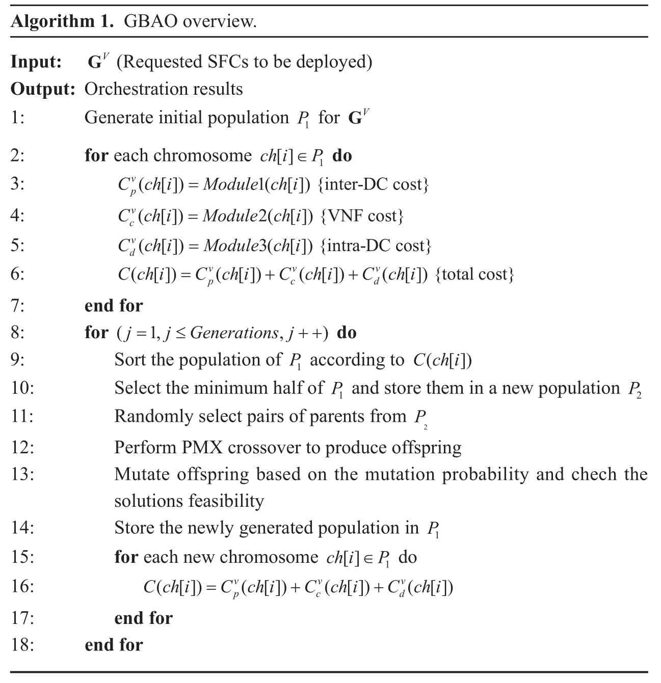
Based on the orchestration procedure proposed in section 4, we design a meta-heuristic algorithm namedGBAOto solve the cost-efficient SFC orchestration problem. It contains three modules. The first module is based onGenetic algorithm to solve the SFCP phase.The second module is based onBest-fit decreasing to solve the VNFC phase. The last module is anArchitecture-aware deployment module to solve the SFGD phase. The fitness value of GBAO is the overallOrchestration cost demonstrated in Equation (1). Algorithm 1 is an overview of GBAO.
Step 1: Population Initialization (line 1).We firstly initialize the population P1based onModule 1: Chromosome Generationin section 5.2, satisfying the location constraint of every NF node.
Step 2: Calculate fitness value (line 2-7).The ithchromosome represented by ch[i]partitions the selected SFC, leading to an inter-DC bandwidth cost represented by(ch[i ]).Module 2: Best-Fit Consolidationin section 5.3 is launched to consolidate the NFs and merge the NFs into SFG. The VNF cost(ch[i]) can be calculated out.Module 3: Architecture-aware Deploymentin section 5.4 is used to deploy the SFG into the hosts of the data centers. Then intra-DC bandwidth cost(ch[i]) can be calculated. The fitness value for every chromosome is the sum of,and.
Step 3: Selection (line 9-11). After we get the fitness value, selection is carried out to select the parent chromosomes for the reproduction of the offspring. We select out the best half chromosomes with respect to the minimum fitness score as the parent chromosomes.
Step 4: Crossover (line 12). Crossover is performed on the parent chromosomes. We use the partial-mapped crossover (PMX) to select crossover points at random. In this method parents are mapped to each other generating new offspring.
Step 5: Mutation (line 13). The newly generated offspring undergoes mutation. Check the feasibility of the newly generated solutions.
Step 6: Iteration (line 14-18). The population in P1is updated. Calculate the fitness values of the newly generated individuals and get the optimal solution through iteration.
5.2 Module 1: chromosome generation
?
We design a chromosome structure to partition the SFCs while satisfying the location constraints of every NF node. Chromosome,in a genetic algorithm based approach, is the potential solution that is scored for its fitness towards a given object. A chromosome contains multiple alleles. In our approach, a chromosome represents a feasible solution of the SFC partition. The number of alleles in each chromosome is equal to the number of NFs requested in the SFC. The chromosome is described through an example.
The chromosome is described through an example. In Figure 2, ch[1] contains three alleles, allele(1), allele(2) and allele(3). The three alleles represent the partition of SFC1,SFC2 and SFC3 respectively. The partition of SFC1 is denoted by allele(1):223, which means that the first two nodes of SFC1 are divided in DC2 and the last one is divided in DC3. Other SFCs are partitioned in the same way. Traffic routes between data centers using the shortest path algorithm. The partition costof ch[1] can be calculated based on Equation (5).
5.3 Module 2: best-fit consolidation
As is mentioned above, after module 1, the SFCs are partitioned into multiple sub-SFCs to be deployed in different data centers. The VNF instances can be shared by multiple NFs with the same type to increase the resource utilization. VNFP tries to pack all NFs partitioned in a DC with less VNF instances. We treat the NF nodes as items, consider the VNF instances as bins with fixed capacity, then the VNFP problem is transformed into a bin packing problem. In this paper, we employ the best-fit decreasing (BFD) algorithm to pack the same type of NFs. After all the NFs are packed in VNF instances, the links between the NFs are added to the links between the corresponding VNFs. Then the sub-SFCs are consolidated into SFC-graph(s).
In Figure 2, there are two sub-SFCs(NF1→NF3,NF1→NF2→NF 3) partitioned into DC1. The NFs with the same type can be packed into the same VNF instance.Thus R1is generated after packing all the NF nodes. R2and R3in DC2 and DC3 are consolidated in the same way. The VNF instance costcan be calculated according to Equation (11).
5.4 Module 3: architecture-aware deployment
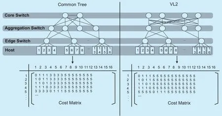
Fig. 3. Cost matrix for common tree and VL2 [25].
After VNFP, the sub-SFCs partitioned in the same data center are consolidated into a SFG.SFGD needs to deploy the service function graph into the data center with less intra-DC bandwidth. The design principle to deploy SFG is divide and conquer. The SFG is cut into pieces after deploying it into an upper tier. One piece is deployed into a lower tier by solving another SFGD problem, yet with a smaller problem size. As the intra-DC bandwidth cost is highly related to the architecture of the data center, we design deployment algorithms for different architectures.
5.4.1 Common tree and VL2
Figure 3 depicts the cost matrice of common tree and VL2, it can be seen:
➢ VNFs deployed in the same server use virtual switch to communicate with each other,therefore the hop is 0.
➢ VNFs deployed in different hosts however connected to the same edge switch communicate with each other with 1 hop.
➢ For common tree, VNFs connected to adjacent edge switches communicate with each other with 3 hops.
➢ VNFs connected to different edge switches communicate with each other using 5 hops.We try to deploy the VNF pairs in SFG with high requested bandwidth in servers with low cost. Therefore, firstly we find all the min-cut for all VNF pairs and compute the Gomory-Hu tree for the SFG [27]. The problem of deploying the SFG is transformed into deploying the Gomory-Hu tree. Secondly, we deploy the Gomory-Hu tree into the data center from the top tier to the bottom. We first select the edge switches for the Gomory-Hu tree. The edge switches are selected following two principles:employing the minimum number of switches and generate the minimum resource fragments.If more than one edge switch are chosen, we cut the tree into sub-trees satisfying the resource capacity of the selected edge-switches.The cut method used here is adapted from the minimum k-cut algorithm in [28]. Then we select the servers for the corresponding sub-tree in the same way. When more than one server are selected, we cut the sub-tree and deploy the VNFs into the corresponding server. Be-sides, since the communication cost between consecutive edge-switches is less for common tree, we choose the consecutive edge-switches in the “edge-switch tier” for “common tree”.Algorithm 2 is the pseudocode for deploying SFG in common tree and VL2. The intra-DC bandwidth cost can be calculated according to Equation (16).
Figure 4(a-b) shows an example of SFG deployment in a common tree. The SFG in Figure 4(a) is firstly constructed into a Gomory-Hu tree. Figure 4(b) deploys the Gomory-Hu tree into a common tree. Firstly, we select continuous edge switches. EdgeSwitch1,EdgeSwitch2 and EdgeSwitch3 who have 2, 1 and 3 empty VNF instances are selected out. The Gormory-Hu tree is cut into three sub-trees satisfying the resource capacity of the selected edge switches. Then we select the hosts of each corresponding edge switch. For EdgeSwitch1, Host1 and Host4 who have 1 and 1 empty VNF instance are selected out.Cut the sub-tree and deploy the VNF instances into the selected hosts.
5.4.2 Fat-tree
Figure 5 depicts the cost matrice of fat-tree, it can be seen:
➢ VNFs deployed in the same server communicate with each other using 0 hop.
➢ VNFs deployed in different servers however connected to the same edge switch communicate with each other with 1 hop.
➢ VNFs connected to different edge switches however deployed in the same pod communicate with each other using 3 hops.
➢ VNFs deployed in different pods communicate with each other using 5 hops.
For fat-tree, there are three tiers to be selected: pod tier, edge switch tier and server tier.We select thethree tiers from top to bottom. We first select the pods and cut the Gomory-Hu tree to satisfy the resource capacity of the corresponding pod. Then we select the edge switches and cut the sub-tree to satisfy the resource capacity of the corresponding edge switch. Finally we select the servers, cut the sub-tree and deploy the requested VNF instances into the selected servers. Algorithm 3 is the pseudocode for deploying SFG in fat-tree.
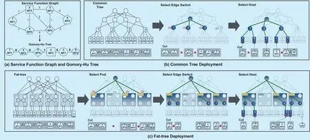
Fig. 4. SFG deployment in data center.
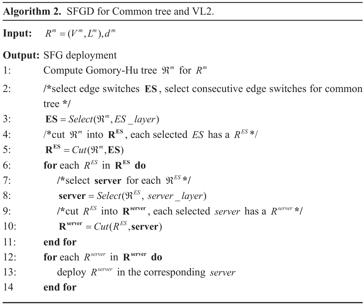
Algorithm 2. SFGD for Common tree and VL2.Input: RVLd=(,),Output: SFG deployment 1: Compute Gomory-Hu tree ℜm for Rm 2: /*select edge switches ES, select consecutive edge switches for common tree */3: ES=SelectℜESlayer(,_)mmmm m m 6: for each RES in RES do 7: /*select server for each ℜES*/8: server=Selectℜserverlayer 4: /*cut ℜm into RES, each selected ES has a RES*/5: RES ES=Cut(ℜ,)(, _)ES 9: /*cut RES into Rserver, each selected server has a Rserver*/10: Rserver server=Cut(R,)ES 11: end for 12: for each Rserver in Rserver do 13: deploy Rserver in the corresponding server 14 end for
In Figure 4(c), the Gomory-Hu tree is deployed into a fat-tree. Firstly Pod1, Pod3 and Pod4, who have 2, 3 and 2 empty instances respectively, are selected for the Gomory-Hu tree. The tree is cut into three parts to satisfy the resource capacity of the selected pods. Secondly, for Pod1, EdgeSwitch1,EdgeSwitch2, who have 1 and 1 empty instance respectively, are selected for the first sub-tree; for Pod3, EdgeSwitch6 who has 2 empty instances is selected for the second sub-tree; for Pod4, EdgeSwitch7 and EdgeSwitch8, who have 1 and 1 empty instance respectively, are selected for the third sub-tree. Then the corresponding sub-tree is cut to satisfy the resource capacity of the selected edge switch. Finally, we select the hosts for each requested VNFs. The intra-DC bandwidth cost(ch[1]) for chromosome ch[1] is calculated according to Equation (8).
VI. SIMULATION RESULTS
6.1 Experimental setup
6.1.1 Parameters setting
Substrate Network. The substrate network is selected from the public topology-zoo which is the most accurate large-scale collection of network topologies available [29]. The bandwidth capacity between data centers is set between [200,300] Gbps which is used in Juniper packet optical DCI solution [30].
Data Center. For all-to-all traffic, it takes unaffordable long time to calculate the network throughput if we use a large network size, thus we set 100 servers in the network.In particular, the fat-tree network under consideration comprises 75 10-port switches and 125 servers [31]. In order to make a fair comparison, we assume that each data center has 125 servers in our simulation. The three architectures (common tree, VL2 and fat-tree)are selected with the same probability. The unit bandwidth cost within DC is randomly selected between [0.002,0.006]$/Mbps. The peering link cost between DCs is randomly selected between [0.006,0.018]$/Mbps. The rationale for the inter-DC and intra-DC cost setting refers to [32]. The price for each type of VNF offered by the DCs is within [0.5, 2]$.VNF instance offered by each DC has [20, 50]units of resources.
Service Function Chain. We set the length of a SFC uniformly distributed between [2,30].The bandwidth within a SFC is uniformly distributed between [10, 100] Mbps [33].
6.1.2 comparison algorithms
We implement our algorithm in Python. We compare our proposed algorithm with GFAO,ABAO and SFC-Greedy.
GFAO. The SFCP is solved by genetic algorithm [34]. The VNFC is solved by first-fit decreasing algorithm. The SFGD is solved by our proposed architecture-aware deployment algorithm.
ABAO. The SFCP is solved by ant colony(AC) algorithm [35]. VNFC is solved by bestfit packing. SFGD is solved by our proposed architecture-aware deployment.
SFC-Greedy. The SFCP is solved by the greedy algorithm. VNFC is solved by best-fit packing. For SFGD phase, it selects the feasible racks and servers and does not consider the data center architectures. To perform side-byside comparison, we modified their algorithm slightly to support the inter-DC orchestration[10].
GBnAO. Compared with GBAO, GBnAO uses the same way to realize SFCP and VNFC,however it directly deploys the VNF one by one into the servers without considering the architecture of the data center.
To perform side-by-side comparison, we modified their algorithm slightly to support the inter-DC orchestration.
6.2 Simulation results and analysis
6.2.1 GBAO observations
In this evaluation, we fix the number of SFC requests and evaluate the relationship between the SFC scale and the iteration number.
Short SFCs. Short SFCs comprise NFs varying from 2 to 10. Figure 6(a) shows the convergence situation for short SFCs containing 3, 6 and 9 NFs. It can be concluded that for SFCs with 3 NFs, GBAO gets convergence when the iteration number approaches to 20 and the total cost is close to 53.3. For SFCs containing 6 NFs, the iteration number is about 32 and the total cost is about 84.2. For the SFCs containing 9 VNFs, GBAO converges after 35 iterations and generates less than 143.9 total cost.

Algorithm 3. SFGD for Fat-tree.Input: RVLd=(,),Output: SFG deployment 1: Compute Gomory-Hu tree ℜm for Rm 2: /*select pod for dm */3: pod=Selectℜpodlayer(,_)mmmm m 4: /*cut ℜm into Rpod, each selected pod has a Rpod*/5: Rpod pod=Cut(ℜ,)m 6: for each Rpod in Rpod do 7: /*select edge switchtes ES for pod*/8: ES=SelectRESlayer(, _)pod 9: /*cut Rpod into RES, each selected ES has a RES*/10: RES ES=Cut(R,)pod 11: for each RES in RES do 12: /*select server for ES*/13: server=SelectRserverlayer(,_)ES 14: /*cut RES into Rserver, each selected server has a Rserver*/15: Rserver server=Cut(R,)ES 16: end for 17: end for 18: for each Rserver in Rserver do 19: deploy Rserver in the corresponding server 20: end for
Medium SFCs. Medium SFCs contain NFs varying from 11 to 20. Figure 6(b) shows the convergence situation for medium SFCs containing 13,16 and 19 NFs. Compared with Figure 6(a), it is obvious that medium SFCs need more times to get convergence. For SFCs with 13 NFs, GBAO converges after 44 iterations and the total cost finally approaches to 174.9.For SFCs with 16 and 19 NFs, the number of iterations is about 38 and 53 respectively, and the total cost reaches to 298.6 and 412.4.
Long SFCs. Long SFCs contain NFs varying from 21 to 30. Figure 6(c) shows the convergence situation for long SFCs with 23, 26 and 29 NFs. Long SFCs need more iteration times to get convergence compared with short and medium SFCs. For SFCs containing 23 NFs, GBAO needs more than 60 iterations to converge to a cost of 982.3. For SFCs with 26 and 29 NFs, it needs 73 and 82 iterations and the costs reach to 1249.3 and 1322.5, respectively.
6.2.2 Composition of the total cost

Fig. 6. GBAO convergence situation for SFCs.
As the total cost includes three parts: inter-DC bandwidth, VNF and intra-DC bandwidth cost,we study the composition of the total cost in this experiment. The number of SFCs ranges from 1000 to 10000, with short, medium and long SFCs each representing one third of the SFC requests.
Inter-DC Bandwidth Cost. Figure 7(a)illustrates the inter-DC bandwidth cost. GFAO and GBAO perform well and use comparable inter-DC bandwidth when the number of SFCs is less than 3500. GFAO increases significantly when the number of SFCs is more than 5500. The low VNF resource utilization makes GFAO suffer from an earlier maturation. SFC-Greedy surpasses the iterative algorithms (GBAO, GFAO and ABAO) when SFC number reaches to 7500. As SFC-Greedy ignores the utilization of the VNF instances,some DCs do not have enough resource to initialize VNFs when there are large amount of SFC requests. It has to partition SFCs with more breakpoints to cope with the incoming SFC requests, thus producing more inter-DC bandwidth cost. ABAO employs more inter-DC bandwidth compared with the GBAO and GFAO. The AC based SFC partition has two main shortcomings: lower convergence speed and earlier maturation. For AC based SFC partition, after each iteration, the pheromone values in ABAO are updated by all the ants that have built solutions, which is less efficient [36]. Secondly, as the pheromone accumulates, AC stops searching early and thus leads to more orchestration cost.
VNF Cost. Figure 7(b) demonstrates the VNF cost. It is conspicuous that GFAO and SFC-Greedy employ more VNF instances.GFAO consolidates the NFs by first fit decreasing (FFD) algorithm. FFD deploys the NF to the first instance which satisfies the resource requirement. Therefore, GFAO uses more VNF instances leading to higher VNF cost. SFC-Greedy employs an arbitrary way to cut the SFCs without considering the utilization of the VNF instances leading to more VNF cost. GBAO and ABAO employ less instances to accomplish the SFC chaining. This is because GBAO and ABAO try to maximize the utilization ratio of each VNF instance in each iteration. ABAO employs more VNF instances when there are more than 6000 requests. The premature convergence of ant colony makes ABAO generates more VNFs to orchestrate SFCs especially when the number of SFCs is bigger.
Intra-DC Bandwidth Cost. Figure 7(c)depicts the intra-DC bandwidth cost. GBAO,ABAO and GFAO employ the architecture-aware deployment strategies, GBnAO and SFC-Greedy directly deploy the VNFs in the SFG one by one, without considering the topologies of the data centers. GBAO,GFAO and ABAO, which employ the architecture-aware deployment strategy, use less intra-DC bandwidth. However, GBnAO and SFC-Greedy use about 35.6% and 41.2%more intra-DC bandwidth compared with other algorithms. GBnAO deploys the same SFG of GBAO, however it does not consider the architecture. We can see GBnAO uses at least 28.6% more intra-DC bandwidth compared with GBAO. The high intra-DC bandwidth cost of GBnAO and SFC-Greedy can be attributed to their the arbitrary deployment strategy. As the data-intensive NFV-enabled applications request for large amount of bandwidth within the service function chain, the strategy to deploy the virtual network function is a main factor influencing the intra-DC bandwidth cost. Moreover, the utilization ratio of VNFs also has an impact on intra-DC bandwidth cost. GFAO uses more intra-DC bandwidth compared with ABAO and GBAO.This is because GFAO employs more VNF instances to deploy the SFCs as is shown in Figure 7(b). Large amount of VNF instances will produce more communication cost within a data center.
Total Cost: Figure 7(d) shows the total cost which is the sum of the inter-DC bandwidth cost depicted in Figure 8(a), the intra-DC bandwidth cost shown in Figure 8(b) and the VNF cost illustrated Figure 8(c). GBAO accomplishes the SFC chaining with at least 21.4% less cost. When the number of SFCs is larger than 6000, the total cost of GBAO is about 37.5% lower cost than the other algorithms.

Fig. 7. Composition of the total cost.

Fig. 8. Compare with the optimal solution.
6.2.3 Optimality of GBAO
To quantify the optimality of GBAO, we solve the ILP problem by IBM CPLEX solver. Due to the inherent complexity of the optimal SFC orchestration problem, the time complexity of the ILP solver turns out to be exponential.Thus, for the comparison between GBAO and CPLEX, we especially carried out simulations on inputs of short SFCs. We try to map the short SFCs ranging from 200 to 1000. It only took about several seconds for GBAO to get a near-optimal solution, while CPLEX took even several hours to compute the optimal solution, which is not practical for large number of SFC requests. Figure 8 shows the total cost comparison. We can observe that GBAO performs well and obtains near optimal solution.For example, when the number of SFC is less than 600, the approximation ratio of GBAO is about 1.13. However, the approximation ratio for GFAO is more than 1.8. When the number of SFC is more than 600, the approximation ratio for GBAO is about 1.23.
VII. CONCLUSION
In this paper, we try to orchestrate SFCs in an inter-DC network with less cost, including the inter-DC bandwidth cost, VNF cost and the intra-DC bandwidth cost. We formulate the problem into a integer linear programming program and prove that it is NP-hard. In order to decrease the complexity, we divide the problem into three phases: service function chain partition, virtual network function consolidation and service function graph deployment. Then a meta-heuristic algorithm GBAO is proposed to solve it. Experimental results show that GBAO accomplishes the SFC chaining in a cost-efficient way compared with the existing algorithms for accommodating the same service function chain requests.
ACKNOWLEDGMENTS
This work was supported by the National Natural Science Foundation of China (61501044).
杂志排行
China Communications的其它文章
- A Precise Information Extraction Algorithm for Lane Lines
- Energy-Efficient Multi-UAV Coverage Deployment in UAV Networks: A Game-Theoretic Framework
- An Efficient Algorithm for Skyline Queries in Cloud Computing Environments
- Cryptanalysis of Key Exchange Protocol Based on Tensor Ergodic Problem
- Physical-Layer Encryption in Massive MIMO Systems with Spatial Modulation
- A Robust Energy Efficiency Power Allocation Algorithm in Cognitive Radio Networks