Parametric Modeling of Circuit Model for AC Glow Discharge in Air
2018-10-11an
,an , ,
Jiangsu Province Key Laboratory of Aerospace Power Systems, College of Energy and Power Engineering, Nanjing University of Aeronautics and Astronautics, Nanjing 210016, P.R. China
(Received 14 November 2016; revised 26 December 2016; accepted 5 January 2017)
Abstract:In the parametric modeling of the circuit model for glow discharge in air, a new method for the design of glow discharge circuit model is presented. The new circuit model is an important reference for the design of plasma power supply, the simulation of glow discharge plasma actuator and the simulation of glow discharge plasma anemometer. The modeling approach consists in developing an electrical model of the glow discharge in air based on circuit components. The structure of the circuit model is established according to the theoretical analysis and the experimental device. Then the parameters of the circuit model are obtained based on the circuit analysis. Finally, the circuit model is verified by comparing the simulation current with the experimental current. This model takes into account the whole framework of the air glow discharge including the sheath and the plasma area. The built circuit model is feasible and reliable, thus being instructive for the investigation of the glow discharge in air.
Key words:parametric modeling; glow discharge; circuit model; OrCAD
0 Introduction
The atmospheric pressure glow discharge has more stable discharge characteristics than the other discharge forms such as spark discharge, arc discharge and so on, which makes the plasma produced by the glow discharge in air be widely used in the field of aeronautics and astronautics. Typical applications include the plasma actuator, the aircraft plasma stealth technology, the plasma anemometer for hypersonic gas flow field measurement, and the plasma rocket[1]. Plasma actuators have made significant success in applications ranging from separation control, lift enhancement, drag reduction, and flight control without moving surfaces[2-3]. Moreover the simulation of the plasma actuator had been conducted by many researchers in this field[4-8]. For example, in 2005, Orlov et al. designed out the electric circuit model for a single-dielectric barrier discharge plasma actuator[9], and the obtained simulation results were in good agreement with the experimental results. In recent years, a new type of plasma actuator based on the standard atmospheric pressure uniform glow discharge has been favored by many designers, because it has better properties[10]. However, there is little research on the simulation of plasma actuators based on the uniform glow discharge in air. For the plasma anemometer, thanks to its wide range of airflow velocity measurement, high precision and high signal-to-noise ratio, it has a great application prospect in the hypersonic research field of aviation[11-13]. To design a high precision plasma anemometer, the changing mechanism of the discharge plasma under the gas flow field should be studied through simulations and experiments, and some researchers have already achieved good results in the experimental part, but there is almost no research on the simulation part[11-19]. Inspirations come from the circuit model simulation, so the simulation of a uniform glow discharge plasma actuator and the simulation of a plasma anemometer can also be considered from the perspective of electric circuit models. The modeling study on the AC glow discharge circuit model in air is the preliminary work of the circuit model simulation of plasma actuator and the plasma anemometer.
In addition, the atmospheric pressure glow discharge has also been widely used in material processing, meteorological detection, environmental protection and other fields[20]. These applications of glow discharge are basically achieved in the air environment, however, so far, the simulation of glow discharge in air is still difficult to realize. In 2011, Speranza et al. used the professional multi-physics field simulation software COMSOL to carry out the simulation of AC (alternating current) glow discharge[21]. The simulation conducted by COMSOL software belongs to the numerical simulation, which can help to establish a physical model of glow discharge and analyze the interaction of the various fields and the collision of the particles[22]. However, there are some disadvantages in the numerical simulation, for example, the simulation gas is only single, simulation results are difficult to converge, the calculation time is too long, and it cannot reflect the characteristics of the discharge circuit etc. The above problems can be solved by electrical modeling. Therefore, it is necessary to carry out the circuit model simulation of glow discharge to make up the defects of numerical simulation. Electrical model of the atmospheric pressure glow discharge (APGD) in helium was designed by Enache et al.[23], but helium is a rare gas, it does not have generality and its cost is very high. The air composition is more complex compared to the single gas, and it is difficult to achieve the stable glow discharge in air. Until now, the simulation research in air is still a problem to be solved. Actually, Stark et al. realized the atmospheric pressure glow discharge in air through experiments in 1999[24]. However, few people research the simulation of glow discharge in air.
In order to study the modeling of glow discharge in air, a new circuit model of glow discharge is presented. The built circuit model reflects the electrical characteristics of glow discharge in air, and it can lay a solid foundation for the circuit model simulation of plasma actuator or others.
1 Experimental Set-Up
The experimental arrangement used for this study is shown in Fig.1. The discharge circuit is composed of a power-supply module, two negative feedback coupling circuit modules, a plasma generator, and a data acquisition and processing module. The power-supply module adopts an AC high voltage source. The power supply equipment is CTP-2000K and can output continuously adjustable voltage, whose output voltage is in the range of 0—30 kV. And the power supply output frequency is also adjustable in the range of 5—20 kHz. The plasma generator adopts the structure of needle composed of two metal probes with good conductive performance, and the probe spacing is 3 mm. The negative feedback coupling circuit module is composed of the coupling resistance and the coupling capacitance in series, which can be used for suppressing the positive feedback process of the discharge and improving the stability of the system[25]. As shown in Fig.1,C1=C2,R1=R2, and the data acquisition and processing module contains four parts: The measuring resistanceR0, a high voltage probe, a numerical oscilloscope and the upper computer system[26]. The voltage output by the power-supply module is measured by means of a high voltage probe (Tektronix P6015, band-width: 75 MHz, ratio: 1 000). The discharge current is measured through the measuring resistance (R0) of 50 Ω. The measured current and the voltage waveforms are visualized on a numerical oscilloscope (UNI-T, UTD2102CEX, band-width: 110 MHz). These waveforms and data are transmitted to the upper computer system by an USB interface.
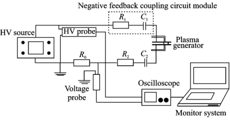
Fig.1 Experimental arrangement
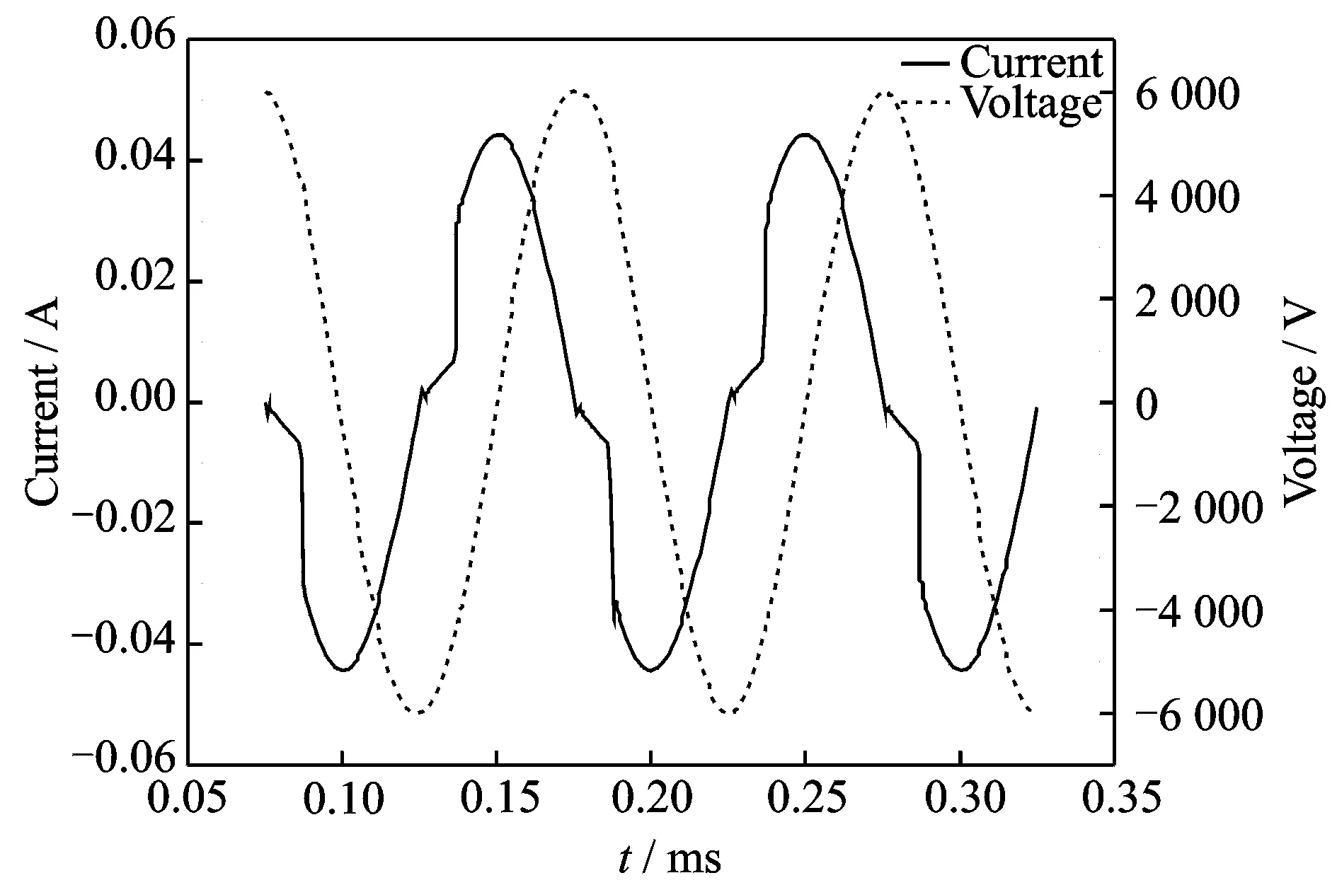
Fig.2 Experimental voltage and current waveforms of glow discharge in air under atmospheric pressure
Fig.2 shows the typical voltage and current waveforms of glow discharge in air under atmospheric pressure through the experiment.
2 Circuit Model of Glow Discharge in Air
The circuit model is built on the basis of the experimental device structure, the theoretical analysis and the experimental results of the glow discharge in air. First, according to the theoretical analysis of the glow discharge in the experiment, the equivalent circuit of each part of the discharge area is proposed, and the circuit principle diagram of the circuit model is constructed. Then the parameters of each component in the circuit model are matched according to the circuit analysis. As described above, it is one way to establish the discharge circuit model.
2.1 Theoretical analysis of glow discharge circuit model
To establish the plasma equivalent circuit model of the experimental equipment, we need to know the discharge characteristics of glow discharge in air under atmospheric pressure. Glow discharge is a phenomenon of gas self-sustaining discharge, and its discharge current is 10-4—10-2A[27]. Glow discharge includes five different regions[28]: Cathode zone (Aston dark space, cathode glow space, Crookes dark space), negative glow, Faraday dark space, positive column, and anode region. In addition to the positive column region, the other areas constitute the sheath[29]. The positive column region is a plasma area[30], in which the electron and ion densities are large and equal, so on the view of macroscopic, it is electrically neutral. In this case, the discharge characteristics and its equivalent circuit structure should be studied from two aspects: The positive column region and the sheath.

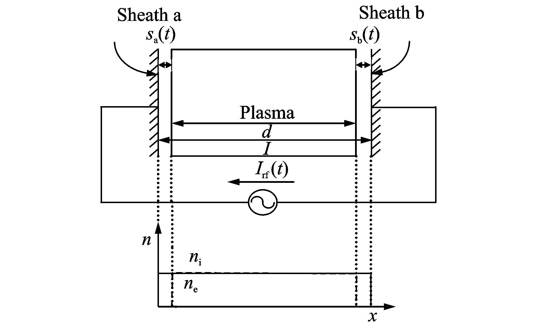
Fig.3 Glow discharge model
2.2 Equivalent circuit of positive column region


(1)

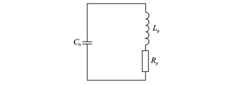
Fig.4 Equivalent circuit of the positive column region
2.3 Equivalent circuit of sheath
Different from the positive column region, the current in the sheath is basically only the displacement current generated by the varying electric field, and the conduction current which is formed by the ion flowing through the sheath to the electrode plate is much smaller than the displacement current[33].
(1) Displacement current
Displacement currentIap(t) that flows through the sheath into the plasma zone can be obtained by analyzing the sheath model.
(2)
whereeis the charge of electron,sais the thickness of the sheath a, and changes with the change of the currentIap(t), andnis the charged particle density.
Analyzing the sheath mode can obtain the voltage drop of sheath a, shown as
(3)
wheres0is the amplitude ofsa.
In the same way, displacement currentIap(t) is
(4)
The voltage drop of sheath b is
(5)
(6)
It is found thatVapandVbpare nonlinear, butVabis linear.
(2) Conduction current
The conduction current in the sheath is very small, that is
(7)
whereuBis the Bohm speed.
Due to symmetry, the time-averaged conduction current that flows to the electrode should be zero in a cycle. In order to satisfy this condition, it is necessary to make the electron in the plasma have the opportunity to reach the polar plate. That is to say, the thickness of the sheath must be zero at a certain time. When the electron is able to reach the electrode plate, the voltage drop of sheath should be reduced to zero. This property of the sheath is very much like an ideal diode, and its positive direction is from the polar plate to the plasma area. From Eq.(6) we can know that the voltage on the two sheaths is a sinusoidal signal, thus a linear sheath capacitanceCscan be defined as follows
(8)
(9)
This analysis shows that the sheath can be composed of a diode, a current source and a capacitor in parallel; electron current is characterized by a diode, constant ion current is characterized by a current source, and displacement current is characterized by a capacitance. The equivalent circuit of the sheath is shown in Fig.5.
2.4 Circuit model of glow discharge in air
The structure of the plasma generator in the experimental device is symmetrical. Therefore, the structure of the whole circuit model can be obtained by analyzing the equivalent circuit of the positive column region and the sheath in the glow discharge. The structure of the whole circuit model is shown in Fig.6.
This is a series circuit, that is, the coupling resistance, the coupling capacitance and the plasma generator are connected in series.
2.5 Matching circuit model parameters
Build the simulation circuit in the circuit simulation software OrCAD. According to the building rules of OrCAD simulation circuit, due to the existence of the sheath capacitance, the coupling capacitance cannot be directly connected in series with the simulation circuit, requiring a high value resistance in parallel with the coupling capacitance.
Simulation circuit is shown in Fig.7. When matching the parameters of the model, the experimental data of voltage and current are read by the oscilloscope. According to the data communication technology between OrCAD and MATALAB, the experimental data of voltage and current are respectively imported into two circuits which are shown in Fig.7. From Fig.7 we can see that experimental voltageVinis imported into the left circuit, and the experimental currentIinis imported into the right circuit. Adjusting the value of the circuit model components to make the simulation current of the left circuit be the same as the experimental current of the right circuit.
In order to match the circuit parameters quickly, we need to analyze the circuit characteristics. The impedance of the positive column region is
(10)
In the case of glow discharge, the impedance of the positive column region is small, and we can get the corresponding parameters according to the theoretical analysis of the positive column region, as described in Section 2.2. The capacitance is calculated by means of the equation, that is
C0=ε0A/d=10 (pF)
(11)
The value of the inductance is calculated according to Eq.(12).
(12)
The equation for the resistance is given as follow
Rp=vmLp=0.1 (Ω)
(13)
The sheath of the discharge area is symmetrical structure in this simulation. And we can get the corresponding parameters according to the theoretical analysis, as described in Section 2.3. The sheath capacitancesC3andC4follow the relation given by Eq.(14).
(14)
whereI1represents the current amplitude. The change ofI1is small, soI1has little effect ons0. In theory,s0≈100 μm.
The constant ion current is characterized by a current source, and it is calculated by Eq.(15).
(15)
The diode is close to an ideal diode as analyzed in Section 2.3, and D1N3940 is adopted in the simulation.
The coupling resistance is 800 Ω and the coupling capacitance is 235 pF in the experiment. The same values are used in this simulation, finally, the simulation circuit model is shown in Fig.7.
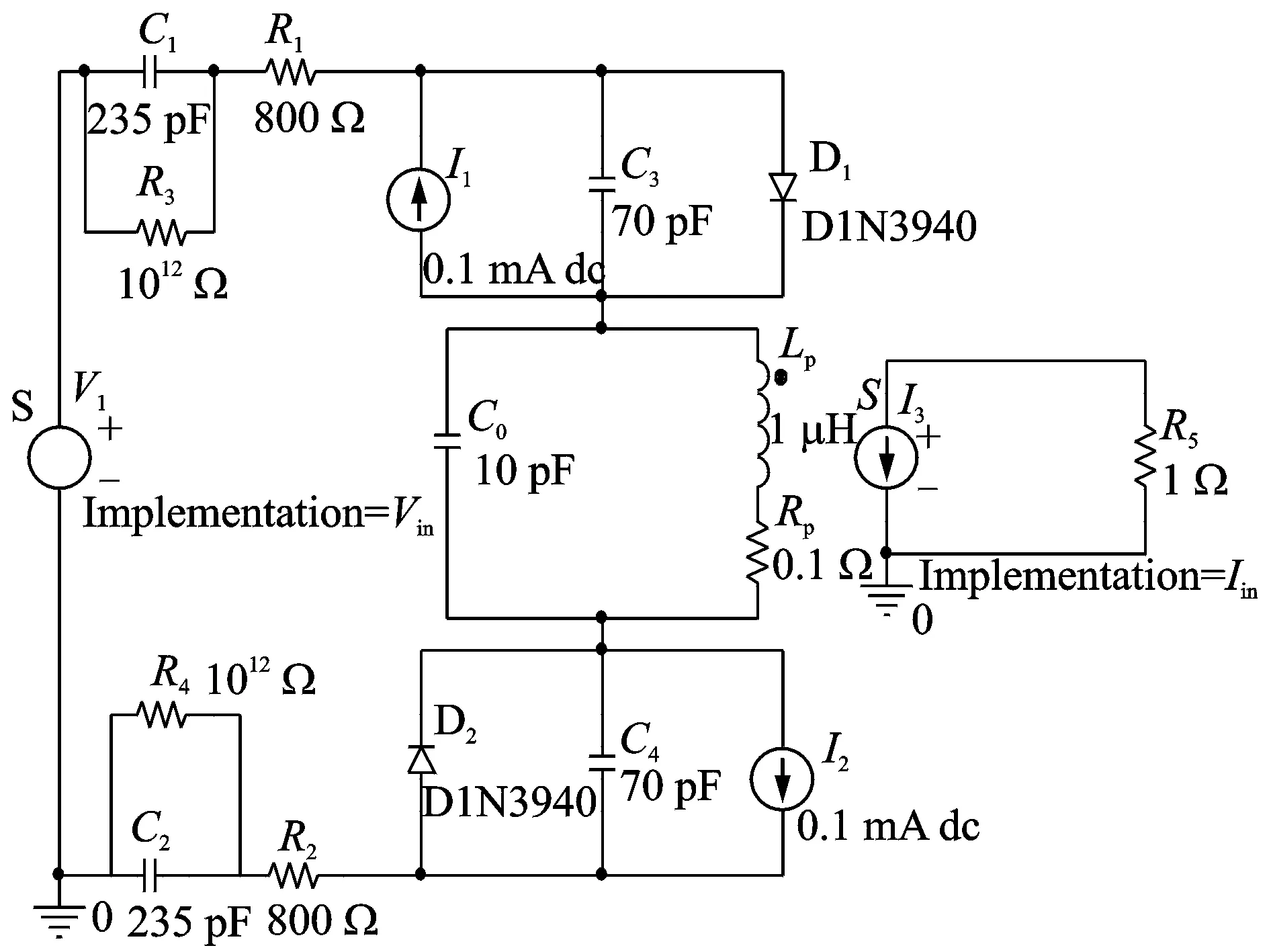
Fig.7 Circuit model simulation diagram
3 Validation of Equivalent Circuit Model
Both experiment and simulation have the negative feedback coupling circuit module, and the parameters are consistent, which ensure the consistency of the external parameters of the plasma generator.
In order to verify the circuit model, in the case of different power supply voltages and frequencies (Figs.8—10), the simulation voltage and current are compared with the experimental voltage and current. Both the simulation voltage and the experimental voltage are derived from the experimental voltage data, so the simulation voltage is the same as the experimental voltage. In the case of the same supply frequency and supply voltage, by comparing the simulation current and the experimental current, it can be seen that the obtained simulation results are in good agreement with the experimental results, the largest current relative error of the three groups is not more than 1.8%, and the correlation coefficients of the experimental currents and simulated currents are 0.998 6, 0.983 5 and 0.990 7,respectively, which are calculated by MATLAB. Therefore, the electrical model is feasible and reliable.
As can be seen from Figs.8—10, the same supply frequency has the same discharge cycle, and the larger supply frequency leads to the smaller discharge cycle. From Figs.8—10, we can also find out: In the case of the same supply frequency, the decrease of the power supply voltage leads to the decrease of the discharge circuit current. In the case of the same power supply voltage, the increase of the supply frequency leads to the increase of the discharge circuit current. These conclusions are consistent with previous research findings[34].
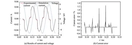
Fig.8 Experimental and simulation results and current error (Supply voltage is 6 kV and supply frequency is 10 kHz)
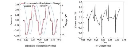
Fig.9 Experimental and simulation results and current error (Supply voltage is 4 kV and supply frequency is 10 kHz)
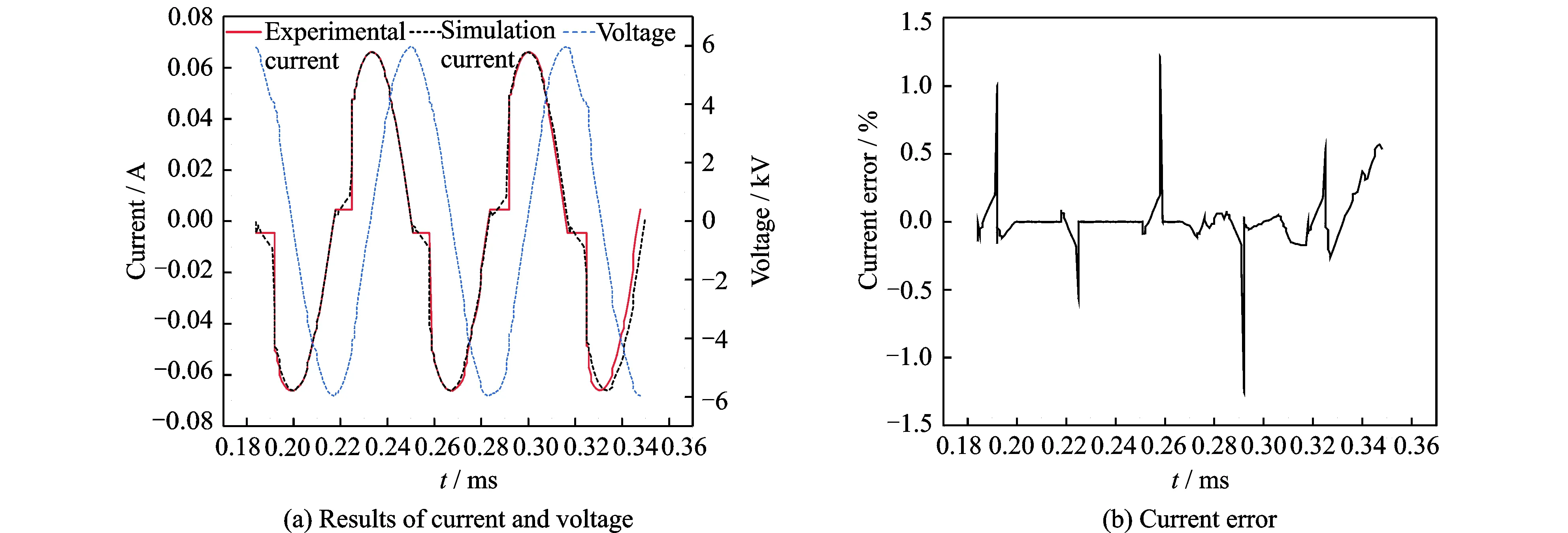
Fig.10 Experimental and simulation results and current error (Supply voltage is 6 kV and supply frequency is 15 kHz)
4 Conclusions
This work presents a circuit model of atmospheric pressure AC glow discharge in air. The circuit model is built on the basis of the experimental device structure and the theoretical analysis of the glow discharge in air, and its equivalent circuit structure is studied from two aspects: The positive column region and the sheath. The positive column region is equivalent to a parallel circuit, which includes a capacitor and a series circuit composed of a resistor and an inductor. The sheath is composed of a diode, a current source and a capacitor in parallel. Finally, the feasibility and reliability of the circuit model are verified by the OrCAD simulation. The circuit characteristics of glow discharge in air are considered by the established circuit model, so it can be used as a tool to study the glow discharge in air, and it can promote the application and development of plasma.In addition, the established circuit model and the existing numerical simulation can complement each other.
Acknowledgements
This work was supported by the Natural Science Foundation of Jiangsu Province (No.BK20140820), the Fundamental Research Funds for the Central Universities (No.NJ20160037), the Natural Science Foundation of China (No.51406083), the Funding of Jiangsu Innovation Program for Graduate Education (No.SJZZ16_0055) , and the Fundamental Research Funds for the Central Universities.
杂志排行
Transactions of Nanjing University of Aeronautics and Astronautics的其它文章
- Adaptive Energy Efficient Power Allocation Scheme for DAS with Multiple Receive Antennas
- Simulation and Analysis of Electromagnetic Force in Laser Melting Deposition by Electromagnetic Impact
- Solid-State Electrolytes for Lithium-Sulfur Batteries
- Facile Fabrication of Hierarchical Porous N/O Functionalized Carbon Derived from Blighted Grains Towards Electrochemical Capacitors
- Solar Cells Based on All-Inorganic Halide Perovskites: Progress and Prospects
- Modeling and Optimal Design of Planar Linkage Mechanism of Coupled Joint Clearances for Manufacturing
