Simulation and Analysis of Electromagnetic Force in Laser Melting Deposition by Electromagnetic Impact
2018-10-11,,,,,
, , , , ,
College of Mechanical and Electrical Engineering, Nanjing University of Aeronautics and Astronautics, Nanjing 210016, P. R. China.
(Received 14 December 2016; revised 13 March 2016; accepted 23 March 2017 )
Abstract:Magnetic field was introduced in laser melting deposition to reduce the pores in workpieces. Finite 3-D model of the coil-deposition layer-substrate was established. Simulation results show that the electromagnetic force in deposition layer mainly concentrates in the projection area of the coil. Axial electromagnetic force shows repulsion in one cycle. The experimental results indicate that the magnetic field is beneficial for grain refinement, microhardness increasement and decline of quantities and average sizes of pores.
Key words:laser melting deposition (LMD); finite element method; electromagnetic force; coil; microstructure
0 Introduction
Laser melting deposition (LMD) is a solid free forming technology which can achieve rapid near-net-shaping of high performance complicated metallic components with full dense and without using a mold[1-3]. However, due to its inherent characteristic—“transient melting process”, microdefects, such as cracks and pores can be found in deposition layers[4]. Thus, many methods, such as process conditions control[5], post processing[6]or the combination of both[7]have been adopted to solve this problem. And in some cases, the product requirements can be met, even exceed the corresponding standards made by homogeneous material[8-9].
Li et al.[10]found that compared with the conventional power laser beam, the inner stress and cracks in deposition layer will reduce a little when using pulsed laser beam to deposite Ni-base superalloy. Scanning parameters and scanning strategies also have significant influence on the microstructure or inner stress distribution in the workpiece[11]. Qi et al.[12]integrated shot peening into the forming process and found that the microstructure of deposition layer was refined to some extent. Xie et al.[13]applied the pulse current into the molten pool and pointed that the magnetic force generated by the current can squeeze the bubble in the molten pool, the experiment proved that number of pores and size of grain in workpiece were reduced.
Electromagnetic force, which has advantages of non-contact, no pollution, high loading speed and easy to automation control, is widely used in the material processing field, such as electromagnetic forming[14-15]and metal welding. Previous studies show that there are two main aspects for the electromagnetic technology to control the cracks: one is by refining the microstructure of the metal, reducing the sensitivity of cracks and pores[16-17]. The second is the transverse plastic elongation of the workpiece produced under the action of electromagnetic force, which can reduce the residual stress[18]. Huang et al.[19]found that the residual stress near the welded seam decreases significantly, when introducing magnetic field perpendicular to the direction of welded seam. Xu et al.[20]adopted pulse electromagnetic force during the process of welding aluminum sheet and the hot cracking tendency was controlled.
A new method that introduces the electromagnetic field into the laser melting deposition process is proposed in this paper, which is aimed at decreasing the porosity, and improving the quality and performance of forming parts.
1 Principle of LMD by Electromagnetic Impact
The excitation device structure is shown in Fig.1.
The device is composed of a flat spiral coil placed in the coaxial position with laser cladding head. A variable magnetic field around space can be created when injecting alternating current into excitation coil during the process of LMD. The changing magnetic field induces eddy currents in the metal workpiece substrate. Eddy current interacts with magnetic field to produce electromagnetic force inside the metal. The synchronous motion of the coil and cladding head can guarantee online continuous operation.
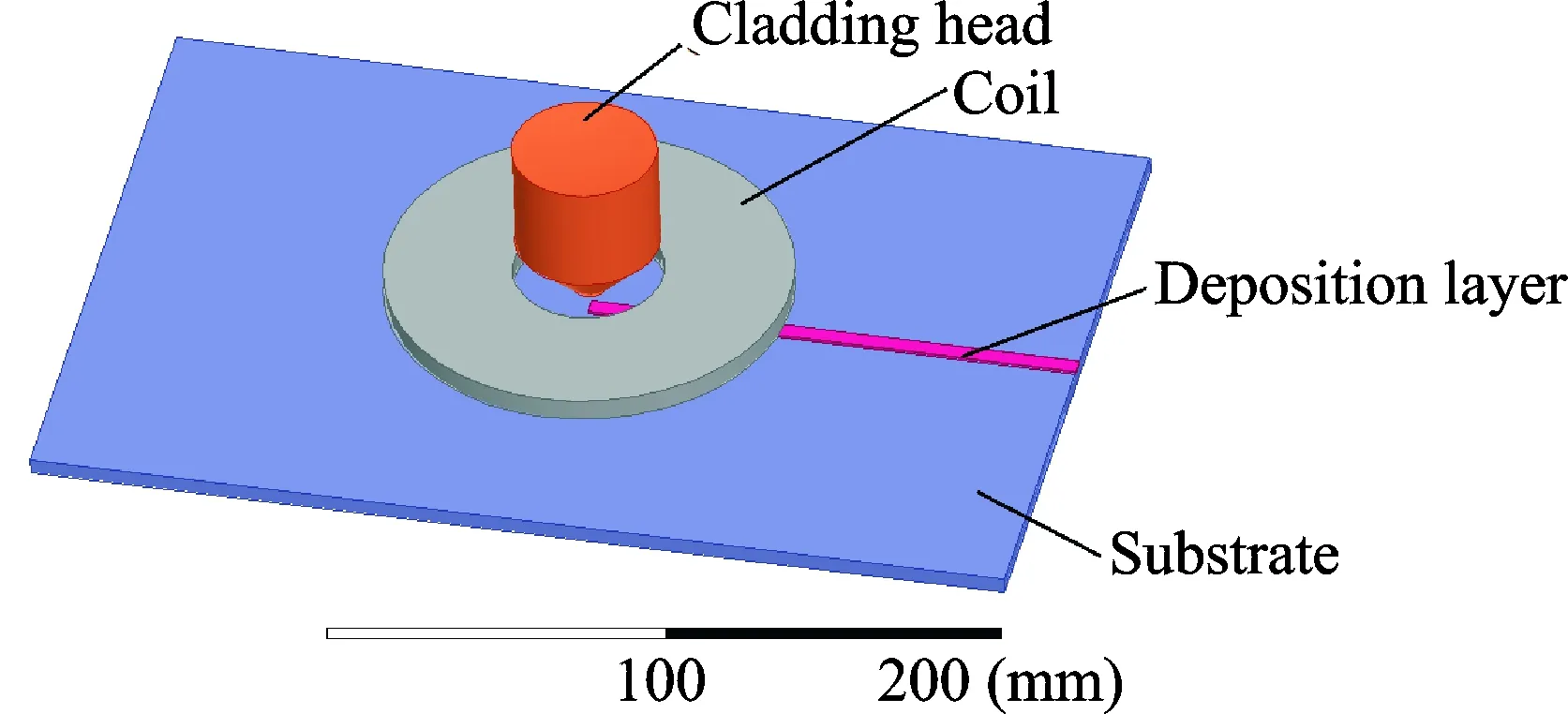
Fig.1 Schematic of LMD by electromagnetic impact
1.1 Derivation of induction current in deposition layer
Fig.2 shows the equivalent circuit diagram of LMD by electromagnetic impact. The equivalent resistance of coil is denoted asR0, while the deposition layer is written asR1. Besides,E11,E10represent self-induced electromotive force and mutual induced electromotive force of deposition layer, respectively. Alternating current passing the exciting coil is recorded as, the induced current in deposition layer represents current angular frequency.
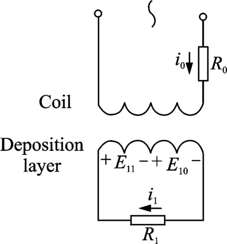
Fig.2 Equivalent circuit diagram of LMD by electromagnetic impact
The voltage equation of the deposition layer is
(1)
whereL1represents the equivalent inductance andMmutual inductance between the coil and deposition layer.
Bring the current into the formula
(2)
Solve Eq.(2) by phasor transformation
(3)
where

1.2 Derivation of magnetic induction intensity of magnetic field induced by coil
To facilitate analysis and calculation, each turn can be divided intoNcircular line currents and the magnitude in each isi'=i0/N. The whole coil is equivalent toN×nlinear currents.i0represents the alternating current in real coil andnthe number of coil. Magnetic field generated by one single circle coil is derived as follows (Fig.3).
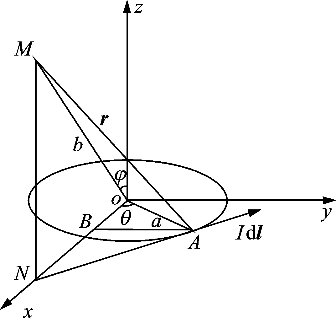
Fig.3 Schematic of circular line current
LetaandIbe the coil radius and the current in the coil. Take any current element in the coil asIdl. Obtained the magnetic induction onMpoint by biot-savart’s law
(4)
LetBx,By,Bz,Brbex-direction,y-direction,z-direction and radial component of magnetic induction intensity. The magnitude of the magnetic induction intensity at any point in space is independent to parameterφdue to the symmetry of circular current. Besides, the magnetic field iny-direction is offset. Therefore
By=0
(5)
Bx=Br
(6)
Magnetic induction intensity ofMpoint can be integrated to obtain
(7)
(8)
Eqs.(7) and (8) can express the magnetic induction intensity at any point in space generated by circular current.
Quasi stationary electromagnetic field is generated due to low frequency of alternating current in the coil. In other words, distribution of electromagnetic field changes synchronously with current distribution and biot-savart’s law is still applicable for this kind of magnetic field. So the magnetic induction intensity of theMpoint is as follows when line current isi'=i0/N
(9)
(10)
Radial and axial magnetic induction intensity of theMpoint generated by all line currents can be written asBTr(t) andBTz(t)
(11)
(12)
1.3 Electromagnetic force of deposited layer
The induced electric field is a kind of vortex field produced by the change of magnetic induction intensity and the power line is closed according to the hypothesis of Maxwell eddy electric field. Thickness of deposition layer could not be too large to avoid holes between the cladding layers when depositing 316L with the LMD[21]. Therefore, only the surface induced current needs to be considered to simplify the calculation model.
Radial magnetic field interacts with eddy current to generate axial electromagnetic force while axial magnetic field interacts with eddy current to generate radial electromagnetic force according to the basic theory of electromagnetic field. The axial electromagnetic force in any one current loop on deposition layer is as follows
dFz(t)=i1dl1×BTr(t)
(13)
Letl1be the current loop, the axial electromagnetic force acts on whole current loop is as follows
(14)
Puti1, andBTrinto Eq.(14)
(15)
Excitation current in the coil and the induced current in deposition layer are shown in Fig.4 according to the equations mentioned above. The induced current is in reverse direction to that of excitation current in the phase between (0,π/2+α) and (π,3π/2+α) while in the same direction between (π/2+α,π) and (3π/2+α,2π). When the current is in opposite direction, the coil and deposition layer’s are equivalent to two homopolar magnets for repulsion. When in the same direction, they are shown as the suction force.

Fig.4 Waveform of excitation current and induced current in deposition layer
From the analysis above, it can be concluded that the electromagnetic force is affected by relative permeability of deposition layer, the coil number, excitation current, inductance, resistance and shape of deposition layer, the mutual inductance between the coil and the deposition layer, etc.
2 Establishment of Finite Element
3-D solid modeling method is established in this paper. Using a stainless steel substrate, the deposition layer is located in the center of the substrate. Experimental data under the present condition of laboratory gives a reference to set the parameters of width and height of deposition layer. To simplify the analysis, the plane spiral coil is expressed by a hollow cylinder as the turn number can be set in Ansoft. There must be a certain height between the coil and the substrate when considering the deposition layer’s height and the spatter in the molten pool. The height is set to be 3 mm. Table 1 shows some important parameters of the system. To simplify the calculation, some assumptions are made: Uniform distribution of current density in the coil. Permeability and conductivity of materials are isotropic. Temperature effect is not taken into account in this analysis process.
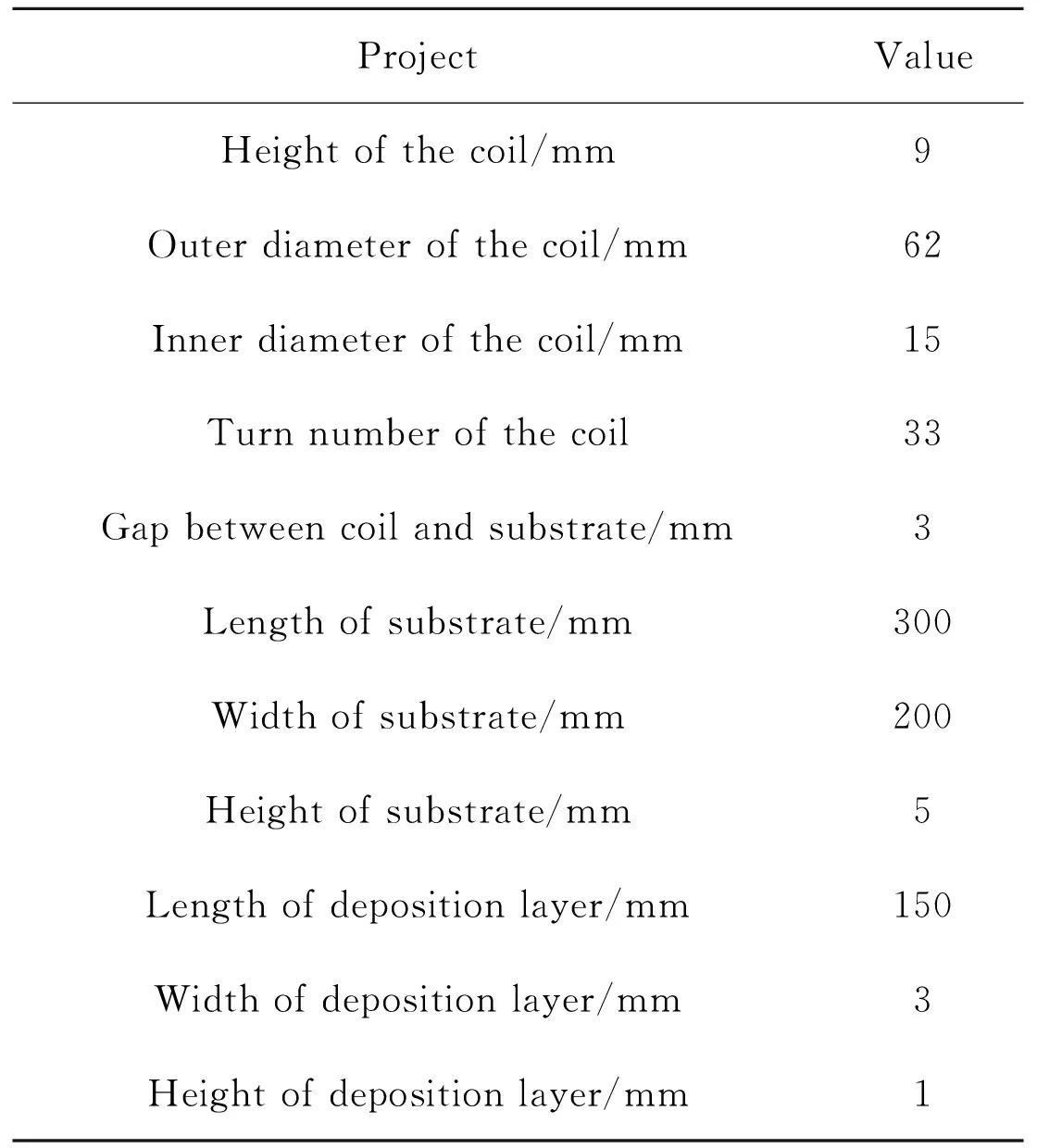
Table 1 Simulation parameters of system
3 Simulation and Analysis Results
The simulation results indicated that electromagnetic force was mainly located in projection of the coil (Fig.5).

Fig.5 Electromagnetic force density of the substrate and deposition layer
In general, the yield strength of the material will be reduced under high temperature. Hence the high temperature zone solidified or just solidified behind the molten pool is the ideal area to use electromagnetic force. So the analysis will focus on the spatial distribution characteristics of electromagnetic force when it reaches to peak.
The electromagnetic force distribution in cross section of deposition layer at the peak time is shown in Fig.6 and the distribution in the whole is shown in Fig.7. Figs.6 and 7 depict that the electromagnetic force has the influence of radial extrusion and axial impact on deposition layer.
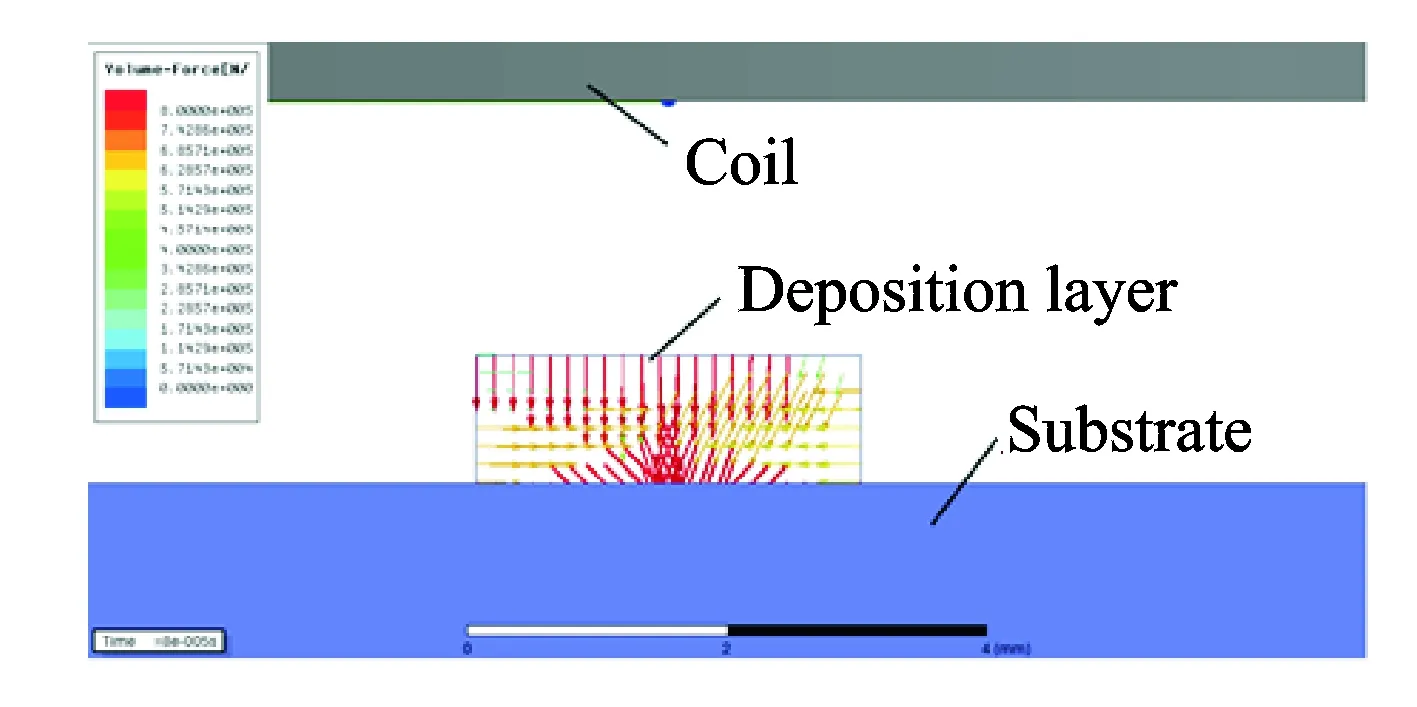
Fig.6 Electromagnetic force vector distribution in cross section of deposition layer at the peak time of force
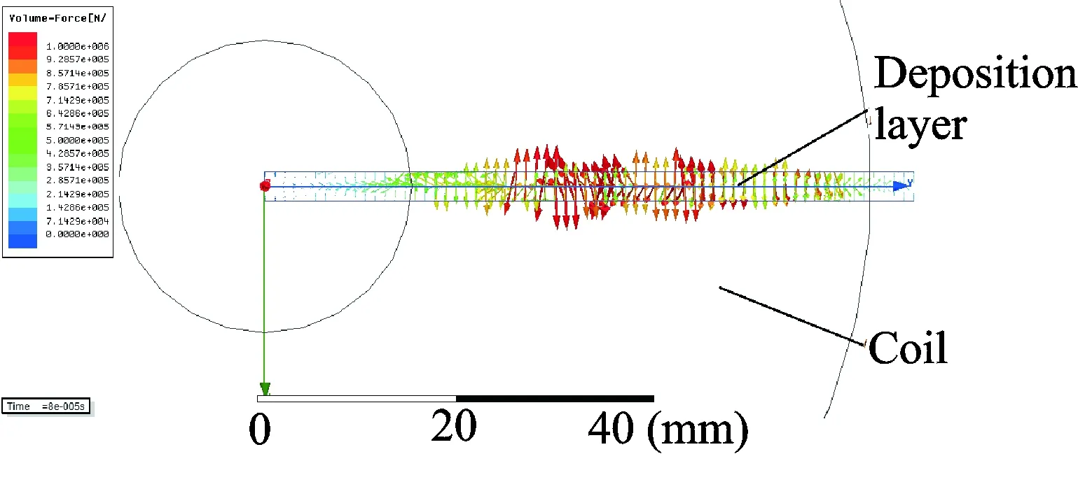
Fig.7 Electromagnetic force vector distribution of the deposition layer at the peak time of force
In order to in-depth study the axial electromagnetic force distribution, the axial electromagnetic force in different depths of the deposition layer (surface, middle, and bottom of layer) is extracted. The results are shown in Fig.8. The axial electromagnetic force density is larger in center of coil radius and decreases to both ends. In detail, the center is almost zero. For different depths of layer, the position characteristics as well as numerical values of electromagnetic force are similar, which indicates that axial electromagnetic force distributes uniformly along the depth of deposition layer.
4 Experiment
4.1 Experimental materials
The substrate was 316L stainless steel and was machined into 500 mm×500 mm×10 mm samples. Table 2 shows its chemical composition. The surfaces of the samples were derusted, unoiled, polished and cleaned for several times with absolute ethylalcohol and acetone to remove the oxide layer and dirt, then dried for using. Iron-based alloy powder of FJ3 was selected as it matched with the parameters performance of 316L. Table 3 showed its chemical composition and the standard granularity of it is 100 μm to 150 μm. The metal powder was put into the drying box at 160 ℃ for one hour and then cooled to room temperature. Finally, it was put into the synchronous powder feeder.
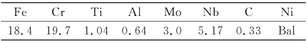
Table 2 Chemical composition of 316L stainless steel(mass fraction) %
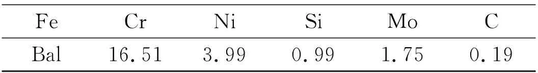
Table 3 Chemical composition of FJ3 iron-based alloy powder(mass fraction) %
4.2 Experimental method
The experiment was completed with TRUMPF TruDisk12003 lasers with the highest power of 12 kW and KUKA60HA high-precision six-axis robot. The parameters of laser processing can be adjusted. Changing the excitation currents and keeping other process parameters constant to study the electromagnetic field effect. The parameters were set as follows: Laser power of 2 500 W, scanning speed of 10 mm/s, defocusing amount of 16 mm, powder delivery amount of 10 g/min, spot diameter of 6 mm. The mode was synchronous powder feeding and the molten pool was protected by argon. The excitation coil was fixed with cladding head coaxially with self-made fixture, the alternating current whose effective value was adjustable (0, 400 and 800 A) passed the coil. Therefore, the magnetic field intensity was adjustable. The deposited sample was placed in the bottom of cladding head, and the scan length was 70 mm.
After depositing, the metallographic specimen was cut perpendicular to the laser scanning direction with linear cutting machine. The specimen was inlayed, grinded and polished, then corroded with the aqua regia (the volume ratio of nitric acid and hydrochloric acid of solution was 1∶3). Microstructures of deposition layers were analyzed with Shanghai CaiKangDMM-1000C metallographic microscope. Microhardness distribution of the section of the deposition layer was measured by ZHVST-1000D microhardness tester, loading of 0.98 N, loading time of 10 s.
4.3 Experimental results and analyses
The microstructures of deposition layers at the same laser process parameters are shown in Fig.9. It can be seen that the bottom of deposition layer is mainly columnar crystal while the middle and upper part is dendrite, small equiaxed grains. Its organization has obvious rapid solidification characteristics and the microstructure is grown from the bottom to the top of the deposition layer. The primary dendrite arm spacing (PDAS) decreased from 5 μm to 3.2 μm with electromagnetic field,which was measured with “Area Method” by metallographic microscope[22]. Electromagnetic force inhibited the growth of dendrite and even broke it[23]. Dendrite developed very well in Fig.9(a) while in Fig.9(c) it was small and more uniform. There were fewer well-developed dendrites in Fig.9(c) than that in Fig.9(b), it can be explained that the greater electromagnetic force was generated to break down the dendrites.
In Fig.9, the black dots in the cross sections of deposition layers are all pores. It can be seen from the figures that the application of electromagnetic field is beneficial to decrease porosity as well as the pore size. The analysis considers that the electromagnetic force in the surface of deposition layer can extrude and impact the better plasticity metal. The impact effect can squeeze the gas out from the high temperature workpiece. As a result the porosity can be eliminated[24].
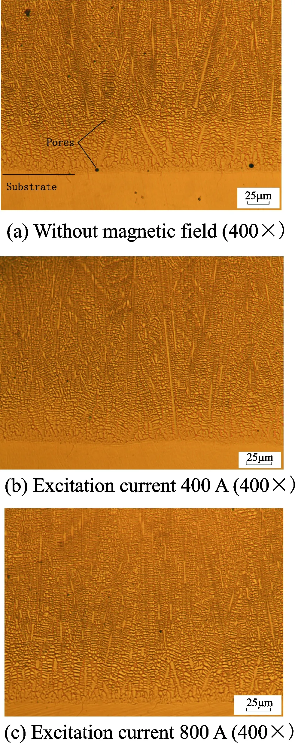
Fig.9 Microstructure of deposition layer at different excitation current
Fig.10 shows the microhardness distribution in cross section of deposition layer.
As demonstrated in Fig.10, the microhardness increases with the distance from the bonding zone. This is due to the rapid solidification characteristics of LMD, the microstructure at the bottom of the deposition layer is coarser. Besides the average microhardness of deposition layer increased after the introduction of magnetic field. In detail, the average microhardness of deposition layer was 1.06 times (350 HV when the current was 400 A) and 1.1 times (369 HV when the current was 800 A) compared with that of made by conventional process(329 HV). It can be interpreted that mechanical properties of the material are significantly related to the microstructure of the material, fine microstructure can improve the mechanical properties of the material. This conforms to the Hall-Petch relationship[25].
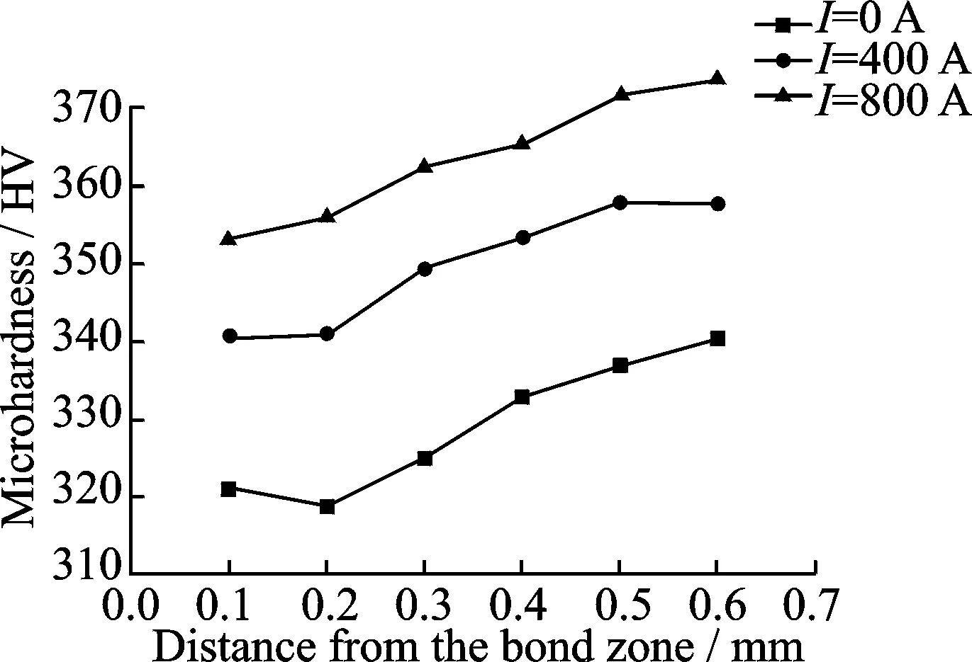
Fig.10 Sectional microhardness curves of deposition layer at different excitation current
5 Conclusions
Electromagnetic force mainly concentrates on the projection of coil according to simulation results. The distribution is consistent with previous experimental results[26]. Electromagnetic force of deposition layer is mainly axial electromagnetic force which shows repulsion in one cycle. Within a certain thickness of deposition layer, the axial electromagnetic force distributes evenly along the depth direction. The experimental results show that application of alternating magnetic field can reduce pores and refine the grain in deposition layer during the process of LMD.
Acknowledgements
This work was supported by the National Science Foundation of China (No.51475238), the Jiangsu Science and Technology Support Program (No.BE2014009-1), and the Jiangsu Provincial Key Research and Development Plan (Nos.BE201561, BE201603-3).
杂志排行

Transactions of Nanjing University of Aeronautics and Astronautics的其它文章
- Local Path Planning and Tracking Control of Vehicle Collision Avoidance System
- Modeling and Optimal Design of Planar Linkage Mechanism of Coupled Joint Clearances for Manufacturing
- A Cause-Selecting Control Chart Method for Monitoring and Diagnosing Dependent Manufacturing Process Stages
- Adaptive Energy Efficient Power Allocation Scheme for DAS with Multiple Receive Antennas
- Solar Cells Based on All-Inorganic Halide Perovskites: Progress and Prospects
- Facile Fabrication of Hierarchical Porous N/O Functionalized Carbon Derived from Blighted Grains Towards Electrochemical Capacitors