Biomass-Derived Nitrogen and Sulfur Co-Doped 3D Carbon Networks with Interconnected Meso-Microporous Structure for High-Performance Supercapacitors
2018-10-11,,,,,
, , , , ,
Jiangsu Key Laboratory of Electrochemical Energy Storage Technologies, College of Material Science and Engineering, Nanjing University of Aeronautics and Astronautics, Nanjing 210016, P.R. China
(Received 12 June 2018; revised 25 July 2018; accepted 28 July 2018)
Abstract:Three-dimensional (3D) carbon networks have been explored as promising capacitive materials thanks to their unique structural features such as large ion-accessible surface area and interconnected porous networks, thus enhancing both ions and electrons transport. Here, sustainable bacterial cellulose (BC) is used both precursor and template for facile synthesis of free-standing N, S-codoped 3D carbon networks (a-NSC) by the pyrolysis and activation of polyrhodanine coated BC. The synthesized a-NSC shows highly conductive interconnected porous networks (24 S·cm-1), large surface area (1 420 m2·g-1) with hierarchical meso-microporosity, and high-level heteroatoms codoping (N: 3.1 % in atom, S: 3.2 % in atom). Benefitting from these, a-NSC as binder-free electrode exhibits an ultrahigh specific capacitance of 340 F·g-1(24 μF·cm-2) at the current density of 0.5 A·g-1in 6 M KOH electrolyte, high-rate capability (71% at 20 A·g-1) and excellent cycle stability. Furthermore, the assembled symmetrical supercapacitor displays a much short time constant of 0.35 s in 1 M TEABF4/AN electrolyte, obtaining a maximum energy density of 32.1 W·h·kg-1at power density of 637 W·kg-1. The in situ multi-heteroatoms doping enables biocellulose-derived carbon networks to exploit its full potentials in energy storage applications, which can be extended to other dimensional carbon nanostructures.
Key words:bacterial cellulose; 3D carbon networks; free-standing; N, S-codoping; supercapacitors
0 Introduction
Electrochemical double-layer capacitors (EDLCs), also known as supercapacitors, store electrical energy at the electrode/electrolyte interface through reversible ion adsorption/ desorption[1-3]. Compared with rechargeable lithium batteries, EDLCs boast higher power density and longer lifespan[4]. However, the low energy density is a major barrier for the practical applications. Considerable efforts have been committed to developing high-capacitance electrode materials or broadening the cell voltage with different electrolytes that can enhance the energy density without sacrificing their existing advantages[5-7]. Porous carbons represent the most attractive class of EDLCs electrode materials owing to large specific surface areas (SSA), high electrical conductivity and chemical stability[8-10]. The commercial EDLCs are mainly constructed using activated carbon electrodes, but only with inferior rate capability because of the sluggish ion diffusion within tortuous microporosity[11]. Thus, engineering hierarchical meso-micropores structure is favorable. The mesopores supply fast ion-diffusion channels with improved rate capability, whilst micropores contribute to abundant active sites for ion adsorption[12-13].
During the last decades, many efforts have been devoted to develop high-performance porous carbons for EDLCs. Especially, the design and preparation of 3D carbon networks assembled from nanofibers are highly desirable owing to their structural advantages as follows: (I) interconnected continuous networks facilitate fast ion/electron transport along 3D directions and ensure structure-buffering space; (II) 1D fiber structure possesses a high surface-to-volume ratio to increase the utilization of SSA for charge accommodation; and (III) nanosized subunits guarantee sufficient contact areas between the electrolyte and active sites[14-16]. David et al. proposed an efficient strategy for carbonization of electrospun ZIF-8@PAN nanofibers to prepare 3D carbon networks, exhibiting a specific capacitance of 307 F·g-1at 1 A·g-1in H2SO4electrolyte[17]. The interconnected graphene fibers were synthesized by hydrothermal treatment of graphene oxide ribbons and consequent laser irradiation[18]. The 3D graphene networks structure effectively eliminates the self-restacking of 2D graphene, maintaining fast axial/radial ion diffusion. Unfortunately, graphene or ZIF-derived carbons were used to construct 3D carbon networks, which usually involved expensive/complicated preparation processes and environmentally unfriendly[19-20]. From the viewpoint of practical application, it is highly desirable to develop a simple and cheap way for fabricating porous carbons in large scale. Currently, many researchers tend to fabricate carbon nanomaterial from biomass, which is low-cost, ecofriendly and easy fabrication[21-23]. Bacterial cellulose (BC), a typical biopolymer, can be obtained by an industrial-scale microbial fermentation process[24]. In terms of microstructure, BC has interconnected porous networks, which consist of random cellulose nanofibers with a diameter of 20—100 nm, thus providing high SSA and porosity[25]. Consequently, it can be an ideal platform for design of value-added carbon-based nanomaterials. Our group recently reported a silica-assisted method for fabrication of carbon nanofiber networks by confining nanospace pyrolysis of BC with a self-activation process[26]. Benefitting from its mesopores-dominated porosity and good conductivity, the as-prepared carbon films display excellent rate performance. Nevertheless, in situ release gas as activator only creates a limited SSA of 624 m2·g-1, leading to an inferior capacitance. The chemical activation has been intensively used to synthesize high-SSA porous carbons[27]. The hierarchical porous carbonaceous aerogels with a large SSA of 2 200 m2·g-1were synthesized through KOH activation of renewable seaweed, achieving multiple energy storage[28].
The capacitance property could be further enhanced by the introduction of heteroatoms into the sp2-hybridized carbon lattice[29]. It has been demonstrated that the incorporation of nitrogen (N) into carbon matrix could not only enhance the conductivity of carbon frameworks, but also significantly increase interface wettability of electrode/electrolyte and induce the additional pseudocapacitance[30-32]. The N-doped ordered mesoporous carbon was prepared by Ni-assisted chemical vapor deposition, manifesting a gravimetric capacitance as high as 855 F·g-1at 1 A·g-1and high-rate performance in aqueous electrolyte[30]. Similarly, doping sulfur (S) into carbon matrix also can decrease charge transfer resistance[33]. Compared to single-atom doping, codoping could take advantage of synergetic effects, thereby benefitting the overall electrochemical performance[34-36]. Qiao et al. revealed a synergistic performance enhancement of N and S dual-doping resulted from the redistribution of spin and charge densities by the experimental and theoretical calculations[34].
Guiding by these, we propose a facile and green route to prepare free-standing N, S-codoped 3D carbon networks by direct pyrolysis and activation of BC@polyrhodanine nanocomposites. The polyrhodanine provides in situ codoping source for both N and S, derived from oxidation polymerization processes. The synthesized carbon nanofibers (a-NSC) present a large SSA with hierarchical meso-micropores structure, interconnected porous networks, high-level N, S-codoping and good electronic conductivity (24 S·cm-1). With these features, a-NSC as binder-free EDLCs electrode achieves a remarkable specific capacitance and high-rate capability in aqueous electrolyte. Moreover, the assembled symmetric EDLCs obtain a high energy density and power density in organic electrolyte. This work offers a low-cost and green route for the design and large-scale preparation of high-performance porous carbons in the energy storage field.
1 Experiment
1.1 Materials synthesis
Polymerization of polyrhodanine on bacterial cellulose: FeCl3(30 mM) dissolved in 30 mL deionized water, followed by vigorous stirring for 1 h. The BC films were immersed into the well-dispersed oxidant solution and stirred slowly for 6 h at room temperature. The obtained BC-Fe (III) films were viscous, displaying a yellow color. Rhodanine monomers (50 mM) were dissolved in 50 mL of deionized water and heated to 60 °C under vigorous stirring to ensure the monomer dissolved completely. The BC-Fe (III) films were added into the prepared rhodanine monomers solution. The in situ oxidative polymerization of rhodanine with BC-Fe (III) was conducted at 60 ℃ for 24 h under magnetic stirring. Finally, the obtained nanocomposite, called as BC@PR, was washed with ethanol and distilled water and freeze-dried overnight.
Preparation of a-NSC, NSC and carbon nanofibers (CNF): The BC@PR was heated with the heating rate of 2 ℃·min-1to 400 ℃ for 1 h, and then with 5 ℃·min-1to 800 ℃ for 2 h under a flowing N2atmosphere, and was called NSC. The NSC and KOH were mixed and heated up with the heating rate of 5 ℃·min-1to 700 ℃ for 1 h in the N2atmosphere. The mass ratio of KOH to NSC was 1∶1. After activation, the products were washed thoroughly with HCl solution (1 M) and lots of distilled water for several times, and dried overnight at 70 ℃. The obtained carbons were denoted by a-NSC. For comparison, BC was direct pyrolyzed under the same condition of NSC, which was noted as CNF.
1.2 Characterizations
The morphologies of samples were characterized by field-emission scanning electron microscopy (SEM) and transmission electron microscopy (TEM) with a Hitachi S-4800I and FEI Tecnai G2F20, respectively. Thermogravimetric analysis was conducted on a TG-DSC instrument (NETZSCH STA 409 PC) under N2protection at heating rate of 10 ℃·min-1from 30 ℃ to 900 ℃. The N2adsorption/desorption technique was carried out using an ASAP 2020 accelerated surface area and porosimetry instrument (Micromeritics BK122T-Banalyzer), equipped with automated surface area, at 77 K using Brunauer-Emmett-Teller (BET) calculations for the surface area. The total pore volume and pore size distribution (PSD) were obtained from the adsorption isotherms using non-local density functional theory (NLDFT) model. The X-ray photoelectron spectroscopy (XPS) analysis was performed on a Perkin-Elmer PHI 550 spectrometer with Al Kα(1 486.6 eV) as the X-ray source. Raman spectra were conducted on the HORIBA Scientific LabRAM HR Raman spectrometer system with a 532.4 nm laser. Fourier transform infrared spectroscopy (FTIR) measurements were recorded on a Nicolet 750. Contact angles of samples were obtained on a video contact angle instrument (JC2000D7M). The electrical conductivity of sample was measured by a standard four-point probe system with a Kiethley 2700 multimeter.
1.3 Electrochemical measurements
All the electrochemical measurements were carried out on a CHI 660D electrochemical workstation. In the three-electrode system, a saturated calomel electrode (SCE) and a platinum plate electrode served as reference and counter electrodes, respectively. The free-standing carbon film (3 mg·cm-2) with thickness of 100 μm was used as working electrode. No binder and additional conductive additive were added. The two symmetrical working electrodes were separated using membrane (GF/A, Whatman) soaked with electrolyte of 1-ethyl-3-methylimidazolium tetrafluoroborate (1 M TEABF4/AN) in a 2016 type cell. The electrochemical impedance spectroscopy (EIS) measurements were performed at open circuit potential in the frequency range of 10-2to 105Hz at an AC amplitude of 5 mV. GCD cycles were tested using a LAND CT2001A electrochemical workstation.
In the three-electrode system, the specific capacitance of electrode calculated based on the discharge curves is according to the following equation
C=(IΔt)/(mΔV)
(1)
whereIis the current loaded (A), Δtthe discharge time (s),mthe active material mass (g), and ΔVthe potential window (V).
In the two-electrode system, the specific capacitance of the electrode was calculated from the discharge curve as
Cs=(4IΔt)/(mΔV)
(2)
whereIis the current loaded (A), Δtthe discharge time (s),mthe total mass for both carbon electrodes (g), and ΔVthe potential window (V).
The gravimetric energy densityEand power densityPagainst two electrodes in device was calculated as
E=CV2/2
(3)
P=E/Δt
(4)
whereCis the capacitance of the symmetric EDLC (based on the total mass of electroactive materials in two electrodes),Vthe operating voltage (deduct the voltage drop), and Δtthe discharge time (s).
2 Results and Discussion
The preparation processes for free-standing N, S-codoped carbon are schematically illustrated in Fig.1(a). The pristine BC pellicle exhibits a gel-like and water-rich macroscopic morphology. The BC was used as template and coated with polyrhodanine (PR) to form the BC@PR nanocomposite with a chemical oxidation polymerization process. Typically, rhodanine monomer fully infiltrates into the 3D networks of BC along the nanofibers through the strong hydrogen bonding. Polymerization of rhodanine onto the surface of BC was induced using Fe(III) ion as the initiator and oxidant. The Fe(III) ion adsorbed on the porous surface of negatively charged BC driven by electrostatic interaction. After carbonization and further KOH activation, a porous N, S-codoped carbon (a-NSC) film was obtained. For comparison, pristine BC-derived carbon nanofibers (CNF) and N, S-codoped carbon (NSC) without activation were synthesized in the same way.
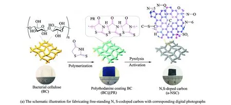
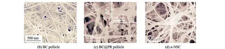
Fig.1 The schematic illustration for fabricating free-standing N, S-codoped carbon with corresponding digital photographs and SEM images of BC pellicle, BC@PR pellicle and a-NSC
As revealed in scanning electron microscopy (SEM) images, BC@PR maintains 3D networks architecture with randomly coadjacent nanofibers of pristine BC (Figs.1(b—c)), displaying a relatively rough surface after the PR coating. After pyrolysis and activation, the resulting a-NSC inherits the structural characteristics of 3D interconnected nanofibrous networks with a slight shrinkage of the frameworks (Fig.1(d)). The diameter of carbon nanofibers is 20—50 nm, as determined by the transmission electron microscopy (TEM) image (Fig.2(a)). And CNF and NSC also preserve an analogous morphology. Notably, the unique interconnected porous networks not only provide a large interfacial area for charge accommodation but also accelerate ion diffusion/electron transfer along 3D directions[37]. As ob-served from high-resolution TEM (Fig.2(b)), a-
NSC mainly consists of relatively disordered structure and partial orientated graphitic layers (002) with an interlayer spacing of about 0.34 nm, which is beneficial to enhance electrical conductivity of carbon materials[38]. X-ray diffraction (XRD) further verifies the structure of CNF, NSC and a-NSC. To a-NSC, two broadened diffraction peaks locating at 24° (002) and 44° (100) imply dominant features of amorphous carbon, which is well-matching the TEM observations[38]. Moreover, there are no other perks (apart from 24° (002) and 44° (100)) which can be observed in the XRD. This case proves that CNF, NSC and a-NSC are pure carbon materials. Typical elemental mapping images of a-NSC (Fig.2(c)) confirmed that homogeneous incorporation of N and S elements into the entire carbon networks.
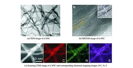

Fig.2 TEM image of a-NSC, HRTEM image of a-NSC (inset: the magnifed graphitic layers), scanning TEM image of a-NSC and corresponding elemental mapping images of C, N, S, N2adsorption/desorption isotherms and the corresponding PSDs of a-NSC, NSC and CNF.

The pore characterization of carbon networks was investigated by the N2adsorption/ desorption experiments. The a-NSC exhibits a hybrid I/IV-type isotherm curve with a distinct hysteresis loop of type H4 in the medium/high pressure region (0.4
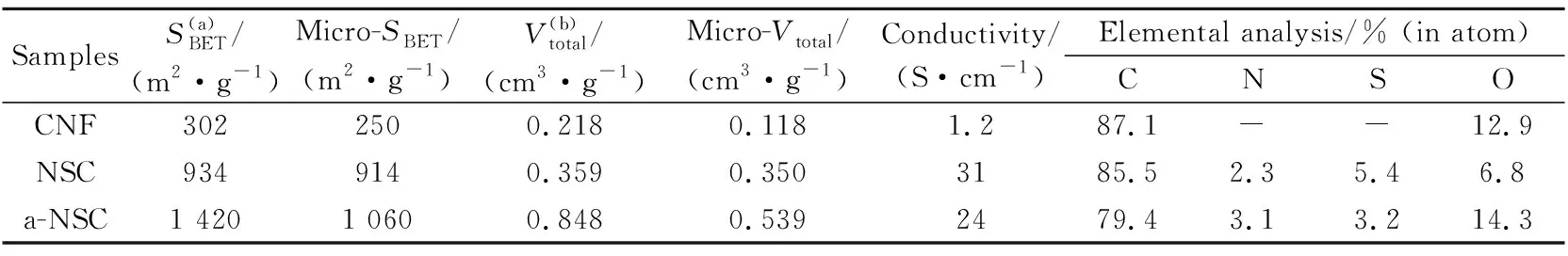
Table 1 BET surface area,pore structure parameters,conductivity tests and XPS elemental analysis of carbon materials
Note: (a) Specific surface area determined according to BET method; (b) Total pore volume.
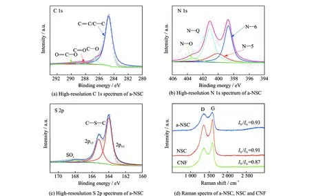
Fig.3 High-resolution C 1s spectrum of a-NSC, high-resolution N 1s spectrum of a-NSC, high-resolution S 2p spectrum of a-NSC, and Raman spectra of a-NSC, NSC and CNF
The as-prepared a-NSC features unique characteristics such as large SSA with hierarchical porosity, interconnected 3D networks morphology and N, S-codoping, which make it an ideal candidate for EDLCs. To investigate capacitive properties, a three-electrode configuration was fabricated with 6M KOH as electrolyte, and carbon film was directly used as binder-free working electrode. As shown in Fig.4(a), both cyclic voltammetry (CV) plots of a-NSC, NSC and CNF display nearly symmetrical rectangular shapes at the scan rate of 10 mV·s-1, demonstrating the formation of ideal electric double-layer (EDL). And the codoped carbon electrodes also showed some redox hump peaks, indicating the pseudocapacitive contribution from N doping. Apparently, the area of CV plot for a-NSC is much larger than the NSC and CNF, suggesting a better EDL behavior. As increasing the scan rate to 200 mV·s-1, a-NSC still keeps a rather good rectangular-like shape. Galvanostatic charge/discharge (GCD) curves of the a-NSC show highly symmetry and nearly linear slopes at different current densities. Comparing with NSC and CNF, a larger discharge time was observed for a-NSC (Fig.4(b)), suggesting a higher capacitance. The specific capacitances were calculated according the discharge of GCD curves (Fig.4(c)). The a-NSC possesses a high specific capacitance of 340 F·g-1at the current density 0.5 A·g-1with superior rate capability of 240 F·g-1at 20 A·g-1(71%), which is much higher than that of the NSC (254 F·g-1at 0.5 A·g-1, 66% at 20 A·g-1), CNF (219 F·g-1at 0.5 A·g-1, 50% at 20 A·g-1), and most other BC-derived carbons for EDLCs applications. Apparently, the enhanced micropore SSA and N, S-functionalization upon doping improve the rate performance and capacitance of NSC electrode; further activation achieved a large SSA with hierarchical meso-microporosity, ensuring the high capacitance and excellent rate characteristic of a-NSC electrode. The BET area-normalized capacitance of a-NSC can achieve a maximum of 24 μF ·cm-2. The improved ion-transport kinetics of electrodes were evidenced by electrochemical impedance spectroscopic (EIS) over a frequency range from 100 kHz to 10 MHz. a-NSC shows a smaller diameter of the semicircle in high-frequency ranges and shorter Warburg region with typical 45° slope than NSC and CNF, proving excellent ion diffusion/charge transfer process. And nearly vertical plot in low-frequency ranges suggests the good accessibility of electrolyte ions into porous carbon. The cycling performance of electrodes were evaluated by 5 000 GCD cycles at 2 A·g-1at 6 M KOH electrolyte in Fig.4(d). Both a-NSC and NSC exhibit high stability with 98% and 99% capacitance retention, respectively, which is far superior to the CNF (80%).
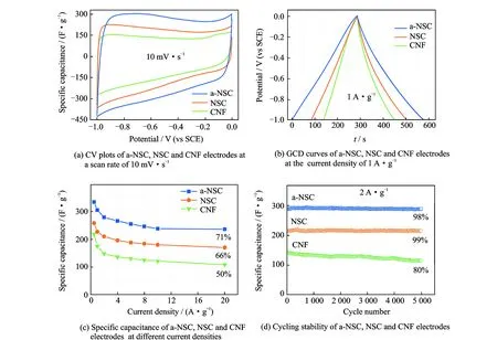
Fig.4 Electrochemical performances using 6 M KOH as electrolyte in a three-electrode configuration
Such excellent capacitive performance can be attributed to unique structural advantages. Firstly, large SSA guarantees sufficient active sites for charge storage and hierarchical porosity can accelerate ion accumulation/diffusion, thus improving both capacitance and rate capability; secondly, interconnected 3D networks can construct conducting backbones for fast electron transfer and also provide multiple channels for the migration of ions. Moreover, the better wettability and conductivity owing to N, S-codoping further enhance the ion-accessible surface area and facilitate electron transport, and N—Q incorporated into the graphitic carbon plane (aromaticity C—N framework) can enhance the electrical conductivity of carbon electrode, significantly increasing the capacitance and rate capability. The presence of N—6 and N—5 (electrochemically active) also can introduce pseudocapacitance in the alkaline aqueous solution through the following faradaic reactions[11]

where*C stands for the carbon network.

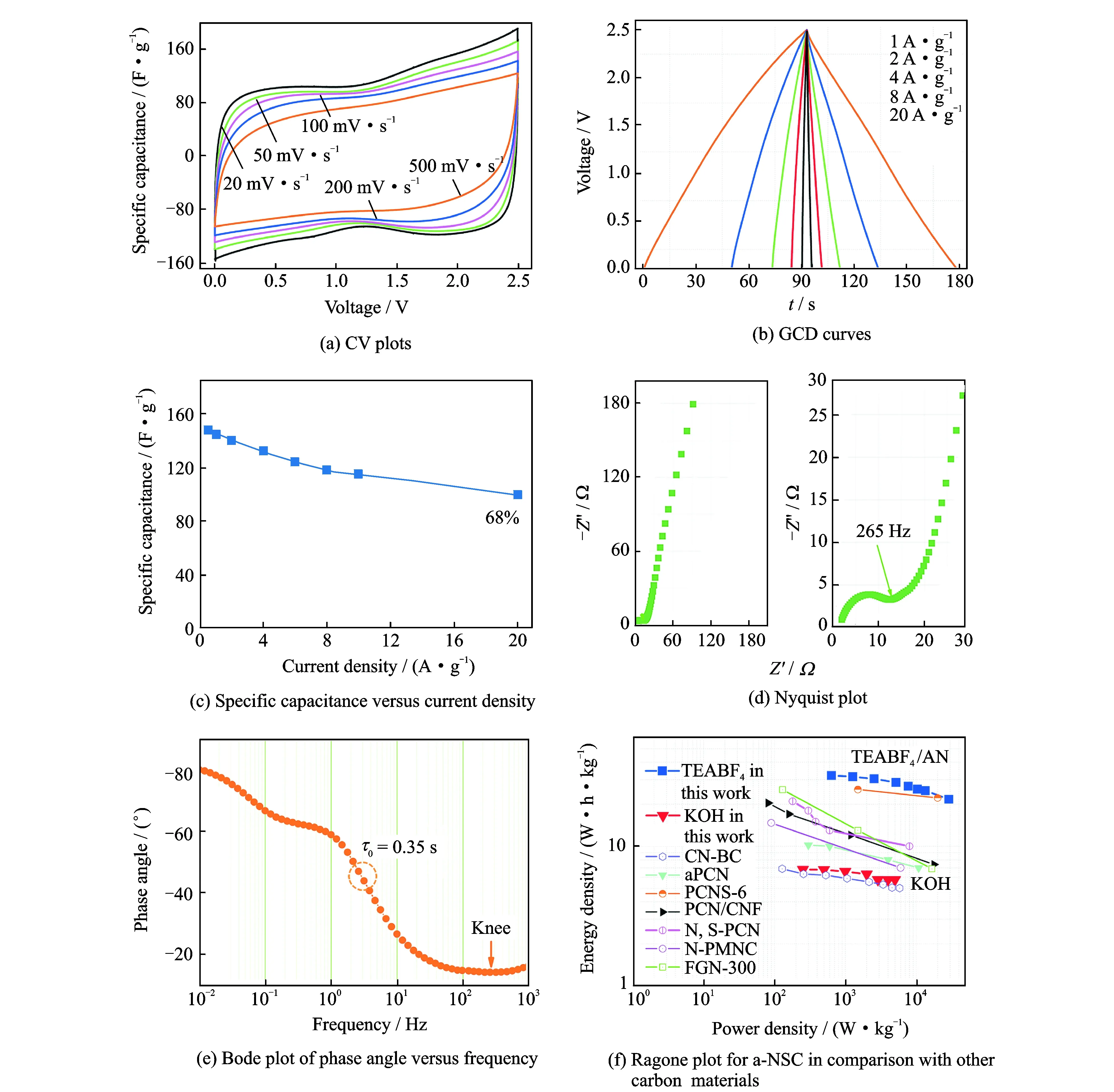
Fig.5 Symmetrical EDLCs performance of a-NSC using 1 M TEABF4/AN as electrolyte, CV plots, GCD curves,specific capacitance versus current density, nyquist plot, bode plot of phase angle versus frequency, ragone plot for a-NSC in comparison with other carbon materials including: CN-BC[26], aPCN[36], PCNS-6[44], PCN/CNF[45], N, S-PCN[46], N-PMNC[47], FGN-300[48]
3 Conclusions
We have successfully synthesized free-standing interconnected N, S-codoped 3D carbon networks (a-NSC) with large SSA and hierarchical meso-microporous structure. This is achieved by the pyrolysis of bacterial cellulose@polyrhodanine derived from oxidation polymerization processes. These structural features not only provide a large ion-accessible surface area for ions adsorption, but also ensure efficient electron and ion transport along 3D directions. As a result, the prepared a-NSC exhibits a high specific capacitance of 340 F·g-1at 0.5 A·g-1in aqueous electrolyte with high-rate capability. Moreover, a symmetrical EDLCs device displays a short time constant of 0.35 s in 1 M TEABF4/AN electrolyte, obtaining a maximum energy density of 32.1 W·h·kg-1at a power density of 637 W·kg-1. We believe that the in situ multi-heteroatoms doping can be extended to other carbon nanostructures (0D, 2D), achieved by using nanosphere or nanosheet precursors as polymerization templates. This versatile method enables biomass-derived porous carbon to exploit its immense potentials in energy storage applications.
Acknowledgements
This work was supported by the National Basic Research Program of China (973 Program) (No. 2014CB239701), the National Natural Science Foundation of China (Nos. 51672128, 51372116, 21773118), the Natural Science Foundation of Jiangsu Province (Nos.BK20150739, BK20151468),the Prospective Joint Research Project of Cooperative Innovation Fund of Jiangsu Province (No.BY2015003-7), and the Project Funded by the Priority Academic Program Development of Jiangsu Higher Education Institutions (PAPD).
杂志排行

Transactions of Nanjing University of Aeronautics and Astronautics的其它文章
- Adaptive Energy Efficient Power Allocation Scheme for DAS with Multiple Receive Antennas
- Parametric Modeling of Circuit Model for AC Glow Discharge in Air
- Solid-State Electrolytes for Lithium-Sulfur Batteries
- Facile Fabrication of Hierarchical Porous N/O Functionalized Carbon Derived from Blighted Grains Towards Electrochemical Capacitors
- Solar Cells Based on All-Inorganic Halide Perovskites: Progress and Prospects
- Modeling and Optimal Design of Planar Linkage Mechanism of Coupled Joint Clearances for Manufacturing